sensor JAGUAR XFR 2010 1.G Workshop Manual
[x] Cancel search | Manufacturer: JAGUAR, Model Year: 2010, Model line: XFR, Model: JAGUAR XFR 2010 1.GPages: 3039, PDF Size: 58.49 MB
Page 1363 of 3039
Defaults to base mapping for the ignition timing, with no cylinder correction
Disables the VCT system.
ENGINE COOLANT TEMPERATURE SENSORS
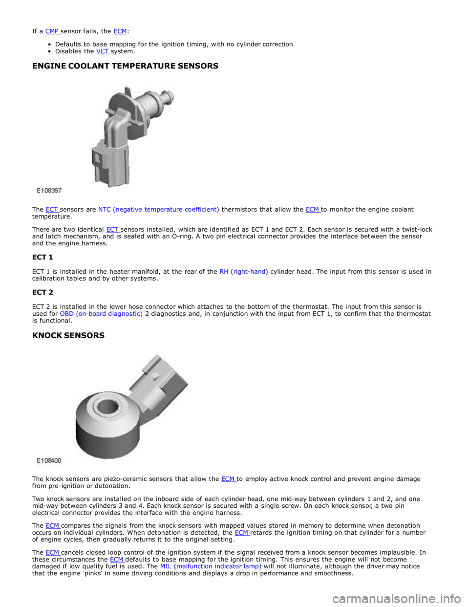
The ECT sensors are NTC (negative temperature coefficient) thermistors that allow the ECM to monitor the engine coolant temperature.
There are two identical ECT sensors installed, which are identified as ECT 1 and ECT 2. Each sensor is secured with a twist-lock and latch mechanism, and is sealed with an O-ring. A two pin electrical connector provides the interface between the sensor
and the engine harness.
ECT 1
ECT 1 is installed in the heater manifold, at the rear of the RH (right-hand) cylinder head. The input from this sensor is used in
calibration tables and by other systems.
ECT 2
ECT 2 is installed in the lower hose connector which attaches to the bottom of the thermostat. The input from this sensor is
used for OBD (on-board diagnostic) 2 diagnostics and, in conjunction with the input from ECT 1, to confirm that the thermostat
is functional.
KNOCK SENSORS
The knock sensors are piezo-ceramic sensors that allow the ECM to employ active knock control and prevent engine damage from pre-ignition or detonation.
Two knock sensors are installed on the inboard side of each cylinder head, one mid-way between cylinders 1 and 2, and one
mid-way between cylinders 3 and 4. Each knock sensor is secured with a single screw. On each knock sensor, a two pin
electrical connector provides the interface with the engine harness.
The ECM compares the signals from the knock sensors with mapped values stored in memory to determine when detonation occurs on individual cylinders. When detonation is detected, the ECM retards the ignition timing on that cylinder for a number of engine cycles, then gradually returns it to the original setting.
The ECM cancels closed loop control of the ignition system if the signal received from a knock sensor becomes implausible. In these circumstances the ECM defaults to base mapping for the ignition timing. This ensures the engine will not become damaged if low quality fuel is used. The MIL (malfunction indicator lamp) will not illuminate, although the driver may notice
that the engine 'pinks' in some driving conditions and displays a drop in performance and smoothness.
Page 1364 of 3039
MANIFOLD ABSOLUTE PRESSURE SENSOR
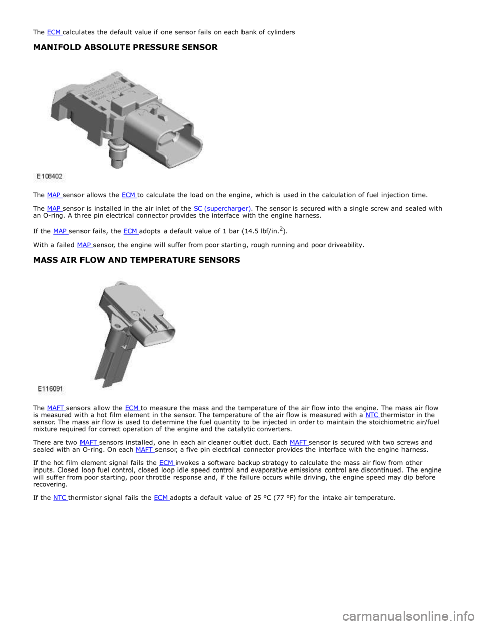
The MAP sensor allows the ECM to calculate the load on the engine, which is used in the calculation of fuel injection time.
The MAP sensor is installed in the air inlet of the SC (supercharger). The sensor is secured with a single screw and sealed with an O-ring. A three pin electrical connector provides the interface with the engine harness.
If the MAP sensor fails, the ECM adopts a default value of 1 bar (14.5 lbf/in.2
). With a failed MAP sensor, the engine will suffer from poor starting, rough running and poor driveability.
MASS AIR FLOW AND TEMPERATURE SENSORS
The MAFT sensors allow the ECM to measure the mass and the temperature of the air flow into the engine. The mass air flow is measured with a hot film element in the sensor. The temperature of the air flow is measured with a NTC thermistor in the sensor. The mass air flow is used to determine the fuel quantity to be injected in order to maintain the stoichiometric air/fuel
mixture required for correct operation of the engine and the catalytic converters.
There are two MAFT sensors installed, one in each air cleaner outlet duct. Each MAFT sensor is secured with two screws and sealed with an O-ring. On each MAFT sensor, a five pin electrical connector provides the interface with the engine harness.
If the hot film element signal fails the ECM invokes a software backup strategy to calculate the mass air flow from other inputs. Closed loop fuel control, closed loop idle speed control and evaporative emissions control are discontinued. The engine
will suffer from poor starting, poor throttle response and, if the failure occurs while driving, the engine speed may dip before
recovering.
If the NTC thermistor signal fails the ECM adopts a default value of 25 °C (77 °F) for the intake air temperature.
Page 1365 of 3039
MANIFOLD ABSOLUTE PRESSURE AND TEMPERATURE SENSOR
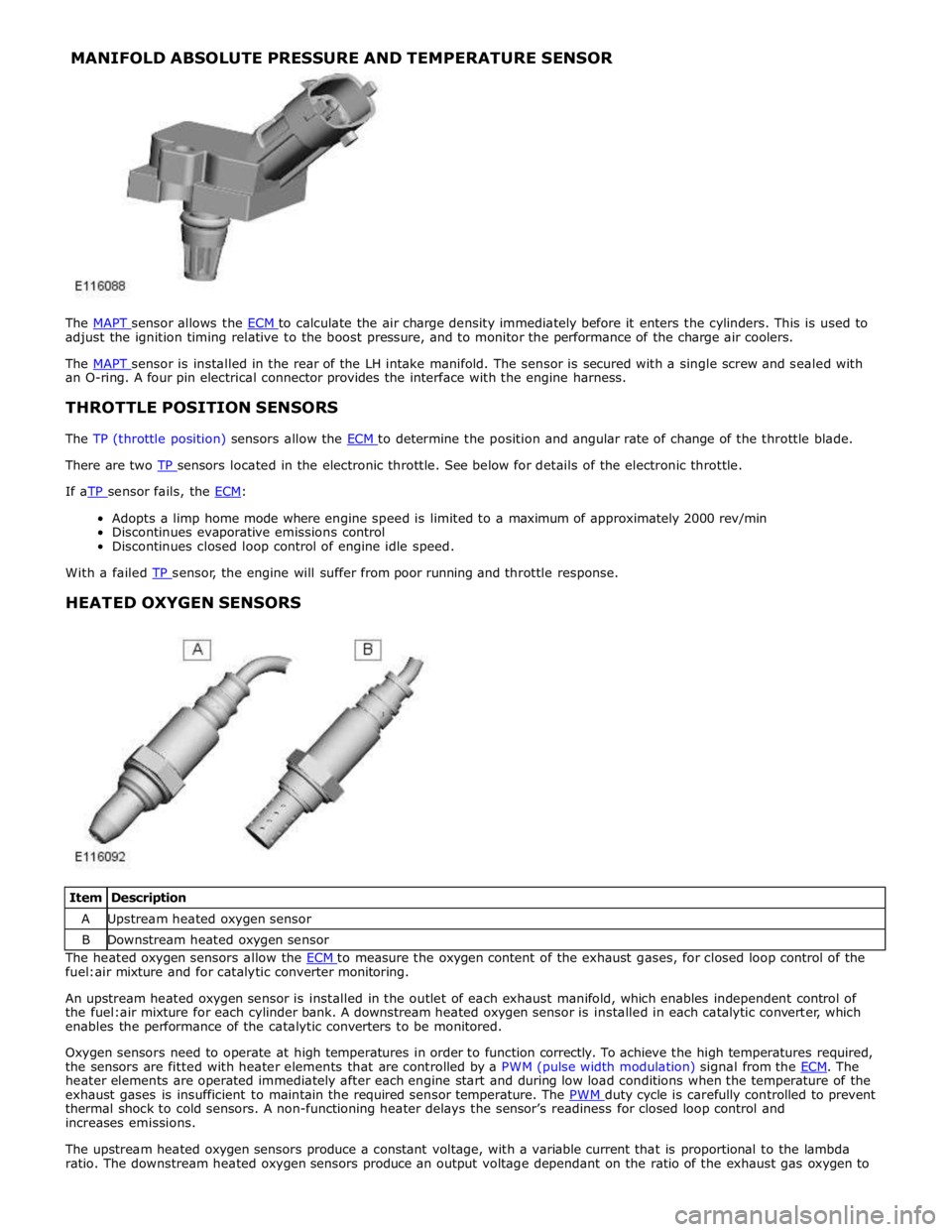
The MAPT sensor allows the ECM to calculate the air charge density immediately before it enters the cylinders. This is used to adjust the ignition timing relative to the boost pressure, and to monitor the performance of the charge air coolers.
The MAPT sensor is installed in the rear of the LH intake manifold. The sensor is secured with a single screw and sealed with an O-ring. A four pin electrical connector provides the interface with the engine harness.
THROTTLE POSITION SENSORS
The TP (throttle position) sensors allow the ECM to determine the position and angular rate of change of the throttle blade. There are two TP sensors located in the electronic throttle. See below for details of the electronic throttle. If aTP sensor fails, the ECM:
Adopts a limp home mode where engine speed is limited to a maximum of approximately 2000 rev/min
Discontinues evaporative emissions control
Discontinues closed loop control of engine idle speed.
With a failed TP sensor, the engine will suffer from poor running and throttle response.
HEATED OXYGEN SENSORS
Item Description A Upstream heated oxygen sensor B Downstream heated oxygen sensor The heated oxygen sensors allow the ECM to measure the oxygen content of the exhaust gases, for closed loop control of the fuel:air mixture and for catalytic converter monitoring.
An upstream heated oxygen sensor is installed in the outlet of each exhaust manifold, which enables independent control of
the fuel:air mixture for each cylinder bank. A downstream heated oxygen sensor is installed in each catalytic converter, which
enables the performance of the catalytic converters to be monitored.
Oxygen sensors need to operate at high temperatures in order to function correctly. To achieve the high temperatures required,
the sensors are fitted with heater elements that are controlled by a PWM (pulse width modulation) signal from the ECM. The heater elements are operated immediately after each engine start and during low load conditions when the temperature of the
exhaust gases is insufficient to maintain the required sensor temperature. The PWM duty cycle is carefully controlled to prevent thermal shock to cold sensors. A non-functioning heater delays the sensor’s readiness for closed loop control and
increases emissions.
The upstream heated oxygen sensors produce a constant voltage, with a variable current that is proportional to the lambda
ratio. The downstream heated oxygen sensors produce an output voltage dependant on the ratio of the exhaust gas oxygen to
Page 1366 of 3039
the period of rich to lean and lean to rich switching monitors the response rate of the upstream sensors.
Diagnosis of electrical faults is continually monitored in both the upstream and downstream sensors. This is achieved by
checking the signal against maximum and minimum threshold, for open and short circuit conditions.
If a heated oxygen sensor fails:
The ECM defaults to open loop fueling for the related cylinder bank The CO (carbon monoxide) and emissions content of the exhaust gases increases
The exhaust smells of rotten eggs (hydrogen sulphide).
With a failed heated oxygen sensor, the engine will suffer from unstable operation and reduced performance.
ACCELERATOR PEDAL POSITION SENSOR
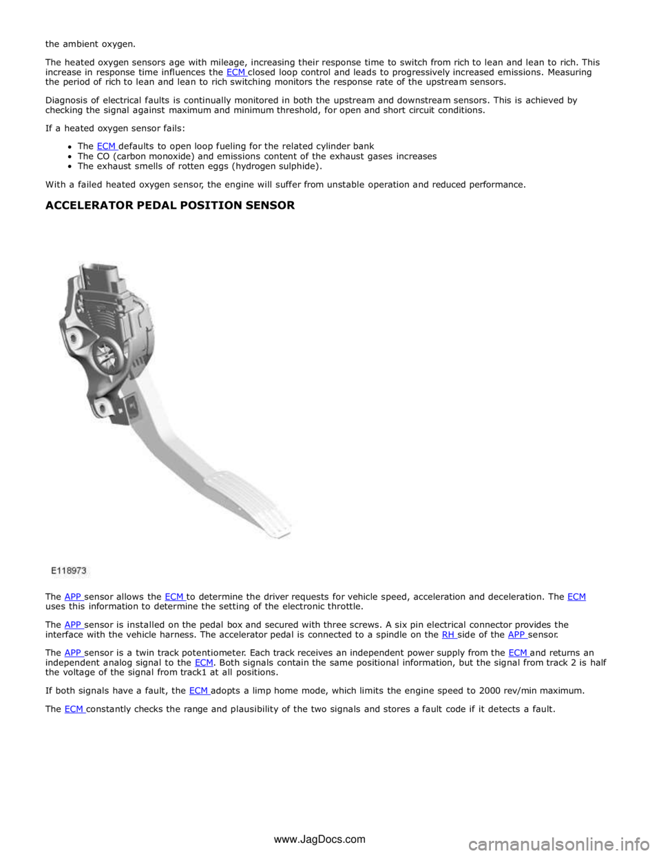
The APP sensor allows the ECM to determine the driver requests for vehicle speed, acceleration and deceleration. The ECM uses this information to determine the setting of the electronic throttle.
The APP sensor is installed on the pedal box and secured with three screws. A six pin electrical connector provides the interface with the vehicle harness. The accelerator pedal is connected to a spindle on the RH side of the APP sensor.
The APP sensor is a twin track potentiometer. Each track receives an independent power supply from the ECM and returns an independent analog signal to the ECM. Both signals contain the same positional information, but the signal from track 2 is half the voltage of the signal from track1 at all positions.
If both signals have a fault, the ECM adopts a limp home mode, which limits the engine speed to 2000 rev/min maximum. The ECM constantly checks the range and plausibility of the two signals and stores a fault code if it detects a fault. www.JagDocs.com
Page 1367 of 3039
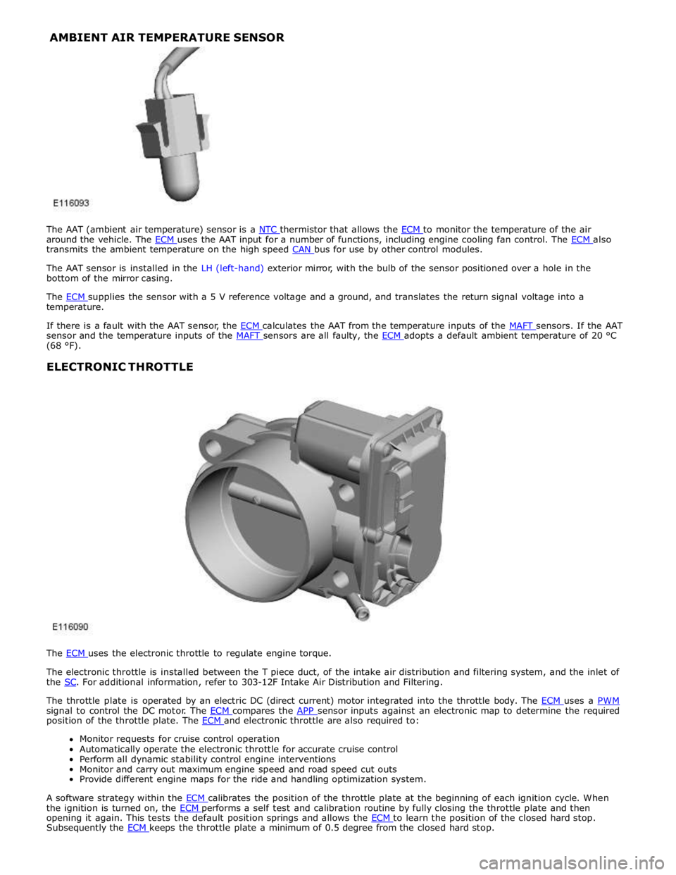
around the vehicle. The ECM uses the AAT input for a number of functions, including engine cooling fan control. The ECM also transmits the ambient temperature on the high speed CAN bus for use by other control modules.
The AAT sensor is installed in the LH (left-hand) exterior mirror, with the bulb of the sensor positioned over a hole in the
bottom of the mirror casing.
The ECM supplies the sensor with a 5 V reference voltage and a ground, and translates the return signal voltage into a temperature.
If there is a fault with the AAT sensor, the ECM calculates the AAT from the temperature inputs of the MAFT sensors. If the AAT sensor and the temperature inputs of the MAFT sensors are all faulty, the ECM adopts a default ambient temperature of 20 °C (68 °F).
ELECTRONIC THROTTLE
The ECM uses the electronic throttle to regulate engine torque.
The electronic throttle is installed between the T piece duct, of the intake air distribution and filtering system, and the inlet of
the SC. For additional information, refer to 303-12F Intake Air Distribution and Filtering.
The throttle plate is operated by an electric DC (direct current) motor integrated into the throttle body. The ECM uses a PWM signal to control the DC motor. The ECM compares the APP sensor inputs against an electronic map to determine the required position of the throttle plate. The ECM and electronic throttle are also required to: Monitor requests for cruise control operation
Automatically operate the electronic throttle for accurate cruise control
Perform all dynamic stability control engine interventions
Monitor and carry out maximum engine speed and road speed cut outs
Provide different engine maps for the ride and handling optimization system.
A software strategy within the ECM calibrates the position of the throttle plate at the beginning of each ignition cycle. When the ignition is turned on, the ECM performs a self test and calibration routine by fully closing the throttle plate and then opening it again. This tests the default position springs and allows the ECM to learn the position of the closed hard stop. Subsequently the ECM keeps the throttle plate a minimum of 0.5 degree from the closed hard stop. AMBIENT AIR TEMPERATURE SENSOR
Page 1369 of 3039

Published: 16-Sep-2013
Electronic Engine Controls - V8 S/C 5.0L Petrol - Electronic Engine Controls
Diagnosis and Testing
Principle of Operation
For a detailed description of electronic engine controls, refer to the relevant Description and Operation section of the workshop
manual. REFER to: (303-14D Electronic Engine Controls - V8 S/C 5.0L Petrol)
Electronic Engine Controls (Description and Operation), Electronic Engine Controls (Description and Operation), Electronic Engine Controls (Description and Operation).
Inspection and Verification
1. Verify the customer concern.
2. Visually inspect for obvious signs of damage and system integrity.
Visual Inspection
Mechanical Electrical
Engine oil level and condition
Cooling system coolant level
Fuel level
Fuel contamination/grade/quality
Throttle body
Front End Accessory Drive (FEAD) belt
Air cleaner condition
Fuses
Wiring harness
Electrical connector(s)
Sensor(s)
Engine Control Module
Transmission Control Module
3. If an obvious cause for an observed or reported concern is found, correct the cause (if possible) before proceeding to
the next step.
4. If the cause is not visually evident, verify the customer concern and refer to the Symptom Chart below, alternatively,
check for Diagnostic Trouble Codes (DTCs) and refer to the DTC Index.
Symptom Chart
Symptom Possible Cause Action Engine non-start Engine does not crank
Security system /Immobilizer
engaged
Engine in shut-down mode
ECM relay
Battery
Starting system
Engine seized
Check that the security system is disarmed
Read DTCs and refer to DTC Index in this
section for ECM relay tests
Ensure the battery is in fully charged and
serviceable condition
For starting system tests refer to the
relevant section of the workshop manual
For engine system tests refer to the relevant
section of the workshop manual Engine cranks, but does not fire
Engine breather system
disconnected/restricted
Ignition system
Fuel system
Electronic engine controls
Ensure the engine breather system is free
from restriction and is correctly installed
For ignition system tests refer to the
relevant section of the workshop manual
For fuel system tests refer to the relevant
section of the workshop manual
Read DTCs and refer to DTC Index in this
section for electronic engine control tests Engine cranks and fires, but will not
start
Evaporative emissions purge
valve
Fuel pump
Spark plugs
Ignition coil failure(s)
For purge valve tests refer to the relevant
section of the workshop manual
For fuel system tests refer to the relevant
section of the workshop manual
For ignition system tests refer to the
relevant section of the workshop manual Difficult to start Difficult cold start
Check engine coolant
level/anti-freeze content
Battery
Electronic engine controls
Exhaust gas recirculation
Check the engine coolant level and
condition. Refer to the relevant sections of
the workshop manual
Ensure the battery is in a fully charged and
serviceable condition. Refer to the battery
Page 1371 of 3039

Symptom Possible Cause Action Engine stalls on overrun
ECM relay
Throttle position (TP)
sensors
Read DTCs and refer to DTC Index in this
section for ECM relay and TP sensor tests Engine stalls at steady speed
ECM relay
crankshaft position sensor
TP sensors
Read DTCs and refer to DTC Index in this
section for ECM relay, crankshaft position
sensor, and TP sensor tests Engine stalls with speed control
enabled
ECM relay
Read DTCs and refer to DTC Index in this
section for ECM relay tests Engine stalls when manoeuvring
ECM relay
TP sensors
Additional engine loads
(PAS, air conditioning, etc)
Transmission malfunction
CAN malfunction
Read DTCs and refer to DTC Index in this
section for ECM relay, and TP sensor tests
Check for excessive loads being placed on
the engine from PAS, air conditioning
systems etc.
Refer to the workshop manual or
transmission troubleshooting guide for
transmission system tests.
Refer to the relevant section of the
workshop manual and the electrical wiring
diagrams to perform CAN network tests. Poor driveability Engine hesitates/poor acceleration
Fuel pressure, fuel pump,
fuel lines
Injector leak
Air leakage
Electronic engine controls
Ignition system
EGR valve stuck
Transmission malfunction
Restricted pedal travel
(carpet, etc)
For fuel system tests refer to the relevant
section of the workshop manual
Carry out fuel injector leak tests, install new
injectors as necessary.
Check for leakage from air intake system
Read DTCs and refer to DTC Index in this
section for electronic engine control tests
For ignition system tests refer to the
relevant section of the workshop manual
Refer to the relevant section of the
workshop manual and check the Exhaust Gas
Recirculation (EGR) valve and associated
hoses and connections.
Refer to the workshop manual or
transmission troubleshooting guide for
transmission system tests.
Ensure accelerator pedal is free from
restriction Engine backfires
Fuel pump, fuel lines
Air leakage
Electronic engine controls
Ignition system
Sticking variable camshaft
timing (VCT) hub
For fuel system tests refer to the relevant
section of the workshop manual
Check for leakage from air intake system
Read DTCs and refer to DTC Index in this
section for electronic engine control tests
For ignition system tests refer to the
relevant section of the workshop manual
Read DTCs and refer to DTC Index in this
section for VCT system tests Engine surges
Fuel pump, fuel lines
Electronic engine controls
Ignition system
For fuel system tests refer to the relevant
section of the workshop manual
Read DTCs and refer to DTC Index in this
section for electronic engine control tests
For ignition system tests refer to the
relevant section of the workshop manual Engine detonates/knocks
Electronic engine controls
Fuel pump, fuel lines, fuel
quality
Air leakage
Sticking VCT hub
Read DTCs and refer to DTC Index in this
section for electronic engine control tests
For fuel system tests refer to the relevant
section of the workshop manual
Check for leakage from air intake system
Read DTCs and refer to DTC Index in this
section for VCT system tests www.JagDocs.com
Page 1373 of 3039

DTC Description Possible Causes Action B10AC-81
Cruise Control Switch -
invalid serial data received
The Engine Control Module
(ECM) has received an invalid
command from the steering
wheel switch pack Clear the DTC and press all the steering wheel
switches, re-check for DTCs. Refer to the
electrical circuit diagrams and check the Cruise
control switch circuit for open circuit, short to
power, short to ground, disconnected. Check
and install a new Steering Wheel Module (SWM) as required. B10AC-82 Cruise Control Switch - alive / sequence counter incorrect / not updated
Cruise Buttons alive counter is
not incrementing. Which
suggests that the LIN bus is
faulty
Steering Wheel Module (SWM) is
not connected
Steering Wheel Module (SWM)
failure Refer to the electrical circuit diagrams and
check the Cruise control switch circuit for open
circuit, short to power, short to ground,
disconnected. Check and install a new Steering
Wheel Module (SWM) as required. B10AC-83
Cruise Control Switch - value
of signal protection
calculation incorrect
Cruise buttons checksum
incorrect, incorrect cruise
switches fitted to vehicle Check and install new cruise switches as
required. B10AC-96
Cruise Control Switch -
component internal failure
Cruise control switch circuit,
open circuit, short to power,
short to ground, disconnected
Cruise Control Switch failure
Steering Wheel Module (SWM)
failure Check for related DTCs in other Central
Junction Box (CJB)s. Refer to the electrical
circuit diagrams and check the Cruise control
switch circuit for open circuit, short to power,
short to ground, disconnected. Check and
install a new cruise control switch as required.
Check and install a new Steering Wheel
Module (SWM) as required. B10FF-68
Ignition Control - Event
information
Spark plug(s) fault
Wiring harness fault
Ignition coil(s) fault Refer to repair manual and check spark plug(s)
for condition and security. Replace any
defective components as required. Refer to
electrical wiring diagrams and check ignition
coil circuit for intermittent open circuit, short
to power, short to ground. Check and install a
new coil(s) as required. B11DB-01
Battery Monitoring Module -
General Electrical Failure
Charging system fault Battery
monitoring signal line
circuit fault
Vehicle battery fault Refer to electrical wiring diagrams and check
charging system for faults. Perform any repairs
required. Refer to the electrical wiring
diagrams and check the Battery Monitoring
System (BMS) module circuit for open circuit,
short to ground, short to power. Refer to the
battery care manual and check and install a
new battery. B11DB-87
Battery Monitoring Module -
missing message
Battery signal line circuit fault Refer to the electrical wiring diagrams and
check the Battery Monitoring System (BMS)
module circuit for open circuit, short to ground,
short to power. B1206-68
Crash Occurred - event
information
Engine control Module (ECM) has
detected the vehicle has crashed
- event information DTC only Refer to the electrical circuit diagrams and
check the Engine Control Module (ECM) to
Restraints Control Module (RCM) circuit for
short to ground, short to power, open circuit.
Repair circuit as required, clear DTC and retest
system to confirm repair. C0031-00
Left Front Wheel Speed
Sensor - No sub type
information
Invalid data received from
Anti-lock Braking System (ABS)
module - left front wheel speed
signal fault Check Anti-lock Braking System (ABS) module
for related DTCs and refer to relevant DTC
Index. C0034-00
Right Front Wheel Speed
Sensor - No sub type
information
Invalid data received from
Anti-lock Braking System (ABS)
module - right front wheel speed
signal fault Check Anti-lock Braking System (ABS) module
for related DTCs and refer to relevant DTC
Index. C0037-00
Left Rear Wheel Speed
Sensor - No sub type
information
Invalid data received from
Anti-lock Braking System (ABS)
module - left rear wheel speed
signal fault Check Anti-lock Braking System (ABS) module
for related DTCs and refer to relevant DTC
Index. C003A-00
Right Rear Wheel Speed
Sensor - No sub type
information
Invalid data received from
Anti-lock Braking System (ABS)
module - right rear wheel speed
signal fault Check Anti-lock Braking System (ABS) module
for related DTCs and refer to relevant DTC
Index.
Page 1376 of 3039

Published: 11-May-2011
Electronic Engine Controls - V8 S/C 5.0L Petrol - Camshaft Position (CMP)
Sensor LH
Removal and Installation
Removal
NOTE: Removal steps in this procedure may contain installation details.
1. Disconnect the battery ground cable.
Refer to: Specifications (414-00 Charging System - General Information,
Specifications).
2. WARNING: Make sure to support the vehicle with axle stands.
Raise and support the vehicle.
3. Refer to: Thermostat Housing - 5.0L SC V8 - AJ133 (303-03 Engine
Cooling - 5.0L NA V8 - AJ133/5.0L SC V8 - AJ133, Removal and
Installation).
Installation
4. NOTE: Some variation in the illustrations may occur,
but the essential information is always correct.
Torque: 10 Nm
1. CAUTIONS:
Make sure that the mating faces are clean and free of foreign
material.
Make sure that the sensor tip is clean and free of foreign material.
NOTE: Lubricate the O-ring seal with clean engine oil.
To install, reverse the removal procedure. www.JagDocs.com
Page 1377 of 3039

Published: 11-May-2011
Electronic Engine Controls - V8 S/C 5.0L Petrol - Camshaft Position (CMP)
Sensor RH
Removal and Installation
Removal
NOTE: Removal steps in this procedure may contain installation details.
1. Disconnect the battery ground cable.
Refer to: Specifications (414-00 Charging System - General Information,
Specifications).
2. WARNING: Make sure to support the vehicle with axle stands.
Raise and support the vehicle.
3. Refer to: Thermostat Housing - 5.0L SC V8 - AJ133 (303-03 Engine
Cooling - 5.0L NA V8 - AJ133/5.0L SC V8 - AJ133, Removal and
Installation).
Installation
4. NOTE: Some variation in the illustrations may occur,
but the essential information is always correct.
Torque: 10 Nm
1. CAUTIONS:
Make sure that the mating faces are clean and free of foreign
material.
Make sure that the sensor tip is clean and free of foreign material.
NOTE: Lubricate the O-ring seal with clean engine oil.
To install, reverse the removal procedure.