steering JAGUAR XFR 2010 1.G Workshop Manual
[x] Cancel search | Manufacturer: JAGUAR, Model Year: 2010, Model line: XFR, Model: JAGUAR XFR 2010 1.GPages: 3039, PDF Size: 58.49 MB
Page 1969 of 3039

1
2
3
1
2
3
4ItemDescription
Touch-s creen
Touch-s creen on/off but ton
Home menu butt on
The fol lowing funct ions are avai lable on the phone menu:
Digi t dialPhone bookLast t en calls (made, received, mis s ed)VoicemailSteering Wheel ControlsItemDescription
Vol ume adjus tment
Scrol l up/down t o next /previ ous memory locat ion.
Audio s ource (Long pres s for ins trument cl us t er mess age cent er phonebook acces s)
JaguarVoice butt on. Briefly press to i nit iat e or end a call. This is al so used for voi ce cont rol functi ons
Addit ional control of t he phone s ys t em i s avai lable in t he form of s t eering wheel mo unted swi tches which are located on
t he left hand s i de of the s t eering wheel. The s wi tches provide for vol ume adjus tment , s croll up/down t o next/previous
memory locati on, i nst rument clus ter mes s age cent er phonebook access and final ly JaguarVoi ce/cal l cont rol.
The s teeri ng wheel control swit ches are hardwired t hrough the cl ock s pri ng t o the ICM (i nformat ion cont rol module). The
ICM (informati on cont rol module) proces ses t he analogue s ignals from the swi tches int o digi tal s ignals . The digit al si gnal s
are then pas sed from t he ICM (informati on cont rol module) onto the MOST (medi a ori ent ated sys tems transport ) s yst em
for control uni t proces s ing and operat ion of t he reques ted funct ions .
JaguarVoice
JaguarVoi ce enables acti vat ion of s everal voi ce act ivat ed functi ons of t he infotainment and cli mate cont rol s ys t ems
wit hout the need t o t ouch any controls manuall y. The foll owi ng s yst ems i ncl ude JaguarVoice funct ional it y;
Navigati on s ys t emPhone sys temCli mate cont rol s ys t emVehicle di spl ay sys t emVehicle not epad
Page 1973 of 3039

Published: 11-May-2011
Information and Entertainment System - Navigation System - Overview
Description and Operation
OVERVIEW
The navigation system provides audible and visual route guidance information to enable the driver to reach a desired
destination. The system allows the driver to choose the desired route using minor or major roads and will present 3 routes to
the driver based on user preferences. Directions to hospitals, museums, monuments and hotels are also available. The
navigation computer uses map information stored on a DVD (digital versatile disc) to determine the best route for the journey
and provide the driver with details of directions and approaching junctions.
The navigation system has various levels of user control through the Touch-screen and JaguarVoice system. System volume
adjustment can be made using the ICP (integrated control panel), Touch-screen and steering wheel controls.
There are 3 navigation system variants specific to various markets. On all systems the GPS (global positioning system) signal
is received by the GPS (global positioning system) antenna located in the roof pod antenna module.
The European navigation system includes the TMC (traffic messaging channel) function, which receives traffic information from
an FM antenna integrated into the heated rear window. On a pre-selected route the system will offer re-routing options
depending on traffic conditions.
The Japanese navigation system includes the VICS (vehicle information and communication systems) function. The VICS
(vehicle information and communication systems) supplies information to enable the navigation computer to re-route the
navigation guidance or to inform the vehicle driver of traffic conditions in the vehicles vicinity. Information is provided to the
system through an FM antenna integrated into the heated rear window and a VICS beacon located in the LH upper side of the
instrument panel.
The NAS (North American specification) variant does not include any additional traffic information systems.
The navigation system is primarily controlled from the Touch-screen which is located in the center of the instrument panel.
Control signals from the Touch-screen are sent on the MOST (media oriented systems transport) ring to the navigation
computer. The navigation computer uses a dedicated GVIF (gigabit video interface) bus to transmit video signals to the Touch-
screen.
Depending upon the audio system version fitted the navigation audio output signals are sent on the MOST (media oriented
systems transport) ring to the IAM (integrated audio module) or the power amplifier for speaker output.
Page 1974 of 3039

Published: 11-May-2011
Information and Entertainment System - Navigation System - System
Operation and Component Description
Description and Operation
Control Diagram
NOTE: A = Hardwired; D = High Speed CAN bus; N = Medium Speed CAN bus; O = LIN bus; P = MOST ring; Q = GVIF; T
= CoAxial
Item Description 1 ABS (anti-lock brake system) module 2 Steering wheel remote audio controls 3 Touch-screen 4 Power amplifier 5 Speakers
Page 1980 of 3039

the roof pod and is shared with the DAB (digital audio broadcasting) band L antenna or satellite radio antenna where fitted.
The roof pod is located externally in a central position towards the rear of the roof.
The GPS antenna is designed with 50 ohm output impedance. The navigation computer is fitted with 50 ohm fakra II connectors to ensure compatibility with the antenna. For optimum performance 50 ohm low loss coaxial cable is used between
the antenna and navigation computer.
It is possible for the GPS antenna to lose the signal from the GPS satellites; In hilly or tree lined areas
Built up areas with tall buildings
In multi storey car parks
In garages
In tunnels
On bridges
During heavy rain or thunderstorms
When the signal is lost the navigation computer will continue to give guidance using memory mapped data from the DVD map until the signal is restored.
TMC/VICS FM Antenna
Data messages for both TMC (traffic message channel) and VICS (vehicle information and communication system) are received
through the FM antennas and diversity antenna module located in the heated rear window.
VICS Beacon Antenna (Japan Only)
The VICS (vehicle information and communication system) beacon antenna receives infra red and RF (radio frequency) traffic
data signals from road side transmitters. The antenna is connected to the navigation computer which incorporates a VICS
(vehicle information and communication system) receiver.
Touch Screen Display
The Touch-screen is the control interface for the following vehicle systems;
System Functions Audio Radio display AM/FM or DAB (digital audio broadcast), auxiliary and portable audio, digital TV or CD Climate
control Air conditioning, distribution, seats, heated steering wheel, automatic air recirculation Telephone Digit dialer, phone book, last ten calls (made, received, missed) www.JagDocs.com
Page 1981 of 3039
Navigation Destination, stored locations, navigation setup, route options Vehicle
Security, parking, valet mode, trip computer, clock, brightness, contrast, system settings, vehicle settings, display settings The screen is a touch sensitive 7 inch LCD (liquid crystal display) VGA screen containing 800 x 480 pixels in a 15:9 format. The
screen processes its own video for system operation but receives the navigation graphics from the navigation computer.
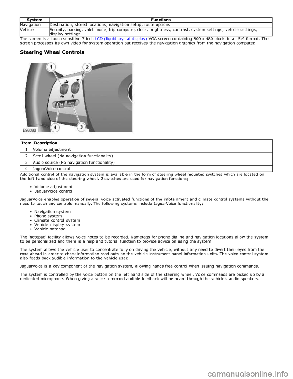
Steering Wheel Controls
Item Description 1 Volume adjustment 2 Scroll wheel (No navigation functionality) 3 Audio source (No navigation functionality) 4 JaguarVoice control Additional control of the navigation system is available in the form of steering wheel mounted switches which are located on
the left hand side of the steering wheel. 2 switches are used for navigation functions;
Volume adjustment
JaguarVoice control
JaguarVoice enables operation of several voice activated functions of the infotainment and climate control systems without the
need to touch any controls manually. The following systems include JaguarVoice functionality;
Navigation system
Phone system
Climate control system
Vehicle display system
Vehicle notepad
The 'notepad' facility allows voice notes to be recorded. Nametags for phone dialing and navigation locations allow the system
to be personalized and there is a help and tutorial function to provide advice on using the system.
The system allows the vehicle user to concentrate fully on driving the vehicle, without any need to divert their eyes from the
road ahead in order to check information read outs on the vehicle instrument panel information units. The voice control system
also feeds back audible information to the vehicle user.
JaguarVoice is a key component of the navigation system, allowing hands free control when issuing navigation commands.
The system is controlled by the voice button on the left hand side of the steering wheel. Voice commands are picked up by a
dedicated microphone. When giving a voice command audible feedback will be heard through the vehicle’s audio speakers.
Page 1989 of 3039
1
2
3
4
5
6
1
2
3
4Touch-s creen
Seek up but ton
Set ti ngs but ton
O n/off and volume cont rol
Source but ton
Seek down but ton
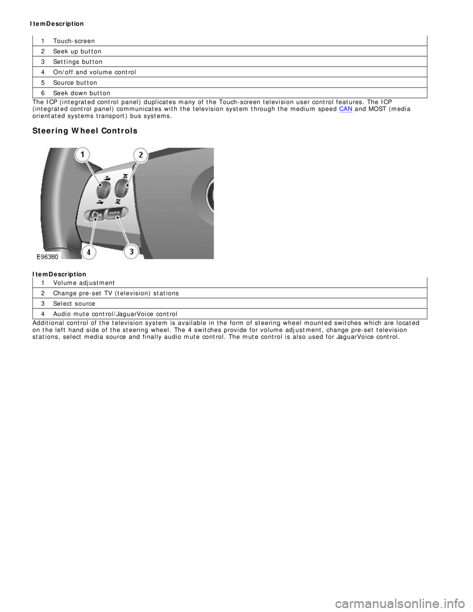
The ICP (i ntegrat ed cont rol panel ) dupl icates many of t he Touch-s creen tel evi si on user control features . The ICP
(integrat ed cont rol panel) communicates wi th the televis i on sys t em t hrough the medium speed CAN and MOST (medi a
ori ent ated sys tems trans port ) bus s ys t ems .
Steering Wheel ControlsItemDescription
Vol ume adjus tment
Change pre-s et TV (t elevis ion) s tat ions
Sel ect s ource
Audio mute cont rol/JaguarVoi ce cont rol
Addit ional control of t he t elevis ion s ys tem is avail abl e in the form of s teeri ng whe el mount ed s wit ches whi ch are l ocat ed
on t he left hand si de of the s t eering wheel . The 4 s wit ches provi de for volume adjus t ment, change pre-s et t elevis ion
s tat ions , sel ect media s ource and fi nal ly audio mute cont rol. The mut e control i s al s o us ed for JaguarVoice cont rol . ItemDescription
Page 2001 of 3039

Published: 11-May-2011
Information and Entertainment System - Steering Wheel Audio Controls
Removal and Installation
Removal
NOTE: Removal steps in this procedure may contain installation details.
1. Make the SRS system safe.
Refer to: Standard Workshop Practices (100-00 General Information, Description and Operation).
2. Refer to: Driver Air Bag Module (501-20B Supplemental Restraint System, Removal and Installation).
3. Refer to: Upshift Paddle Switch (307-05A Automatic Transmission/Transaxle External Controls - V6 3.0L Petrol, Removal and
Installation).
4. Refer to: Downshift Paddle Switch (307-05A Automatic Transmission/Transaxle External Controls - V6 3.0L Petrol, Removal and
Installation).
5. Torque: 3 Nm 6. Torque: 3 Nm
Page 2020 of 3039
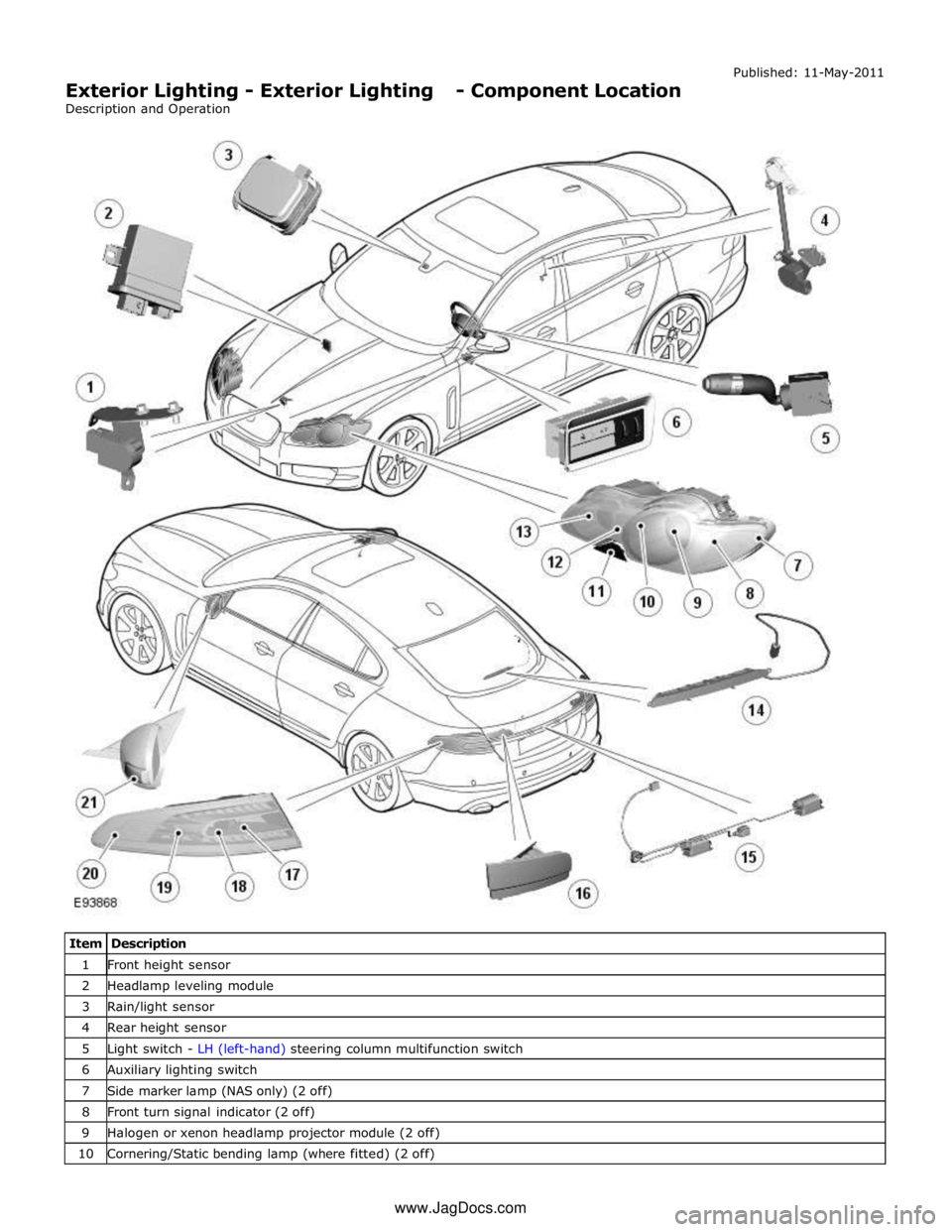
1 Front height sensor 2 Headlamp leveling module 3 Rain/light sensor 4 Rear height sensor 5 Light switch - LH (left-hand) steering column multifunction switch 6 Auxiliary lighting switch 7 Side marker lamp (NAS only) (2 off) 8 Front turn signal indicator (2 off) 9 Halogen or xenon headlamp projector module (2 off) 10 Cornering/Static bending lamp (where fitted) (2 off) www.JagDocs.com
Page 2024 of 3039
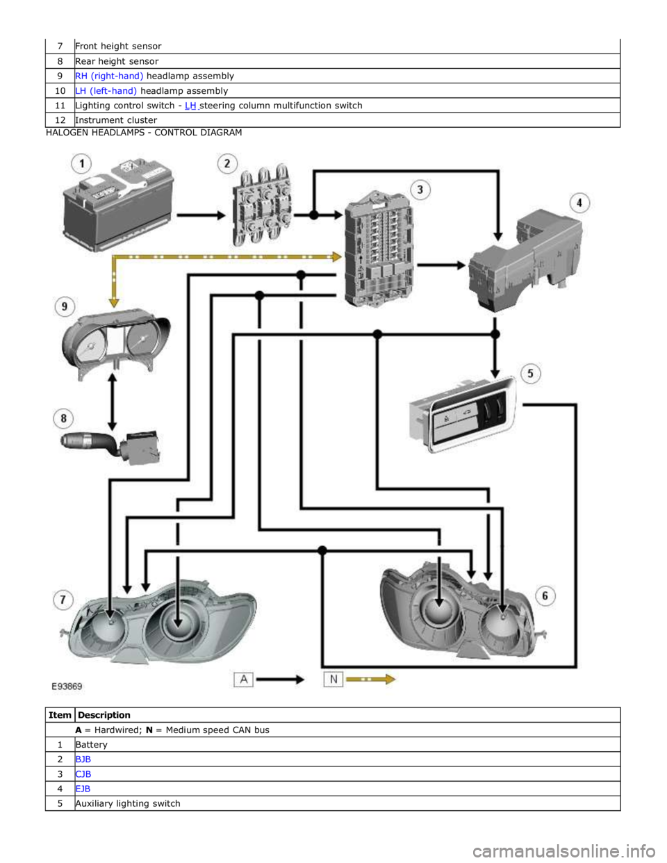
8 Rear height sensor 9 RH (right-hand) headlamp assembly 10 LH (left-hand) headlamp assembly 11 Lighting control switch - LH steering column multifunction switch 12 Instrument cluster HALOGEN HEADLAMPS - CONTROL DIAGRAM
Item Description A = Hardwired; N = Medium speed CAN bus 1 Battery 2 BJB 3 CJB 4 EJB 5 Auxiliary lighting switch
Page 2025 of 3039
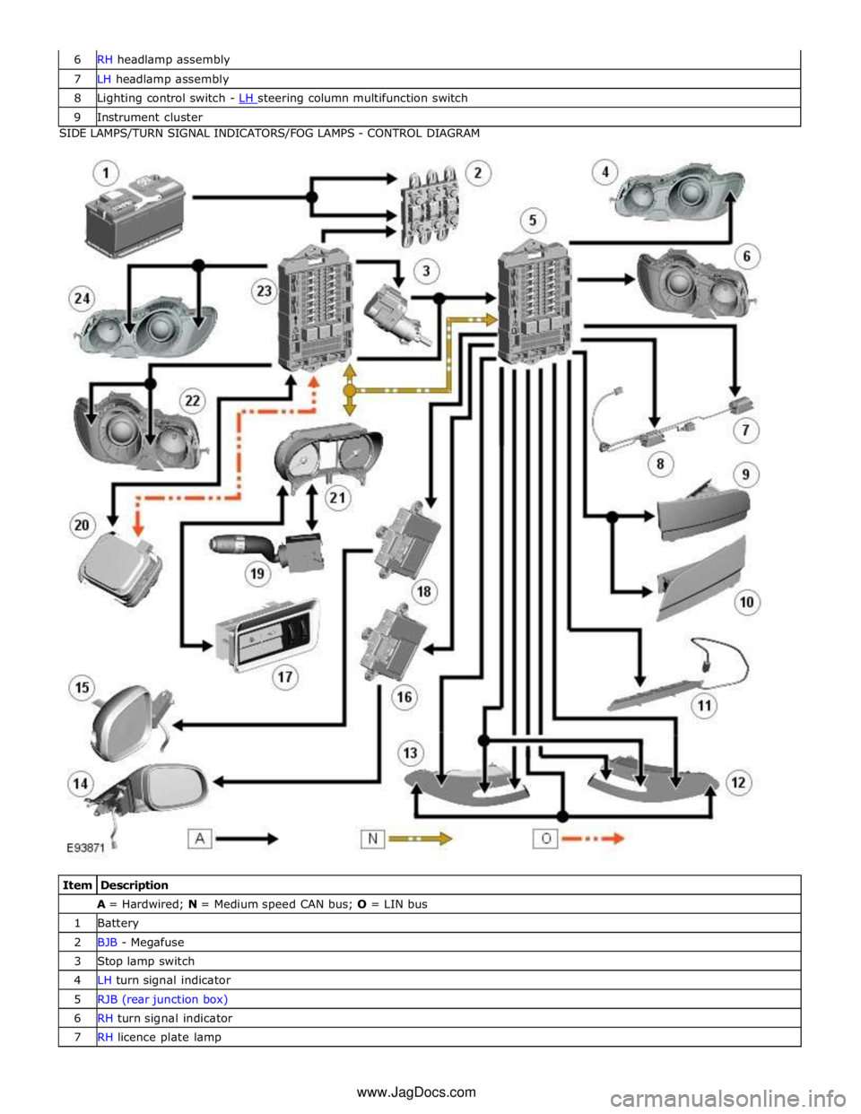
7 LH headlamp assembly 8 Lighting control switch - LH steering column multifunction switch 9 Instrument cluster SIDE LAMPS/TURN SIGNAL INDICATORS/FOG LAMPS - CONTROL DIAGRAM
Item Description A = Hardwired; N = Medium speed CAN bus; O = LIN bus 1 Battery 2 BJB - Megafuse 3 Stop lamp switch 4 LH turn signal indicator 5 RJB (rear junction box) 6 RH turn signal indicator 7 RH licence plate lamp www.JagDocs.com