Oxygen sensor JAGUAR XFR 2010 1.G User Guide
[x] Cancel search | Manufacturer: JAGUAR, Model Year: 2010, Model line: XFR, Model: JAGUAR XFR 2010 1.GPages: 3039, PDF Size: 58.49 MB
Page 1361 of 3039
DIAGNOSTICS
The ECM stores each fault as a DTC (diagnostic trouble code). The DTC and associated environmental and freeze frame data can be read using Jaguar approved diagnostic equipment, which can also read real time data from each sensor, the adaption
values currently being employed and the current fueling, ignition and idle speed settings.
ENGINE CONTROL MODULE Component Description
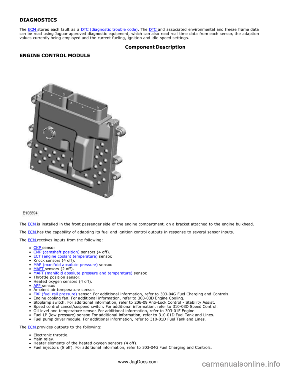
The ECM is installed in the front passenger side of the engine compartment, on a bracket attached to the engine bulkhead. The ECM has the capability of adapting its fuel and ignition control outputs in response to several sensor inputs. The ECM receives inputs from the following:
CKP sensor. CMP (camshaft position) sensors (4 off).
ECT (engine coolant temperature) sensor.
Knock sensors (4 off).
MAP (manifold absolute pressure) sensor.
MAFT sensors (2 off). MAPT (manifold absolute pressure and temperature) sensor.
Throttle position sensor.
Heated oxygen sensors (4 off).
APP sensor. Ambient air temperature sensor.
FRP (fuel rail pressure) sensor. For additional information, refer to 303-04G Fuel Charging and Controls.
Engine cooling fan. For additional information, refer to 303-03D Engine Cooling.
Stoplamp switch. For additional information, refer to 206-09 Anti-Lock Control - Stability Assist.
Speed control cancel/suspend switch. For additional information, refer to 310-03D Speed Control.
Oil level and temperature sensor. For additional information, refer to 303-01F Engine.
Fuel LP (low pressure) sensor. For additional information, refer to 310-01D Fuel Tank and Lines.
Fuel pump driver module. For additional information, refer to 310-01D Fuel Tank and Lines.
The ECM provides outputs to the following: Electronic throttle.
Main relay.
Heater elements of the heated oxygen sensors (4 off).
Fuel injectors (8 off). For additional information, refer to 303-04G Fuel Charging and Controls. www.JagDocs.com
Page 1365 of 3039
MANIFOLD ABSOLUTE PRESSURE AND TEMPERATURE SENSOR
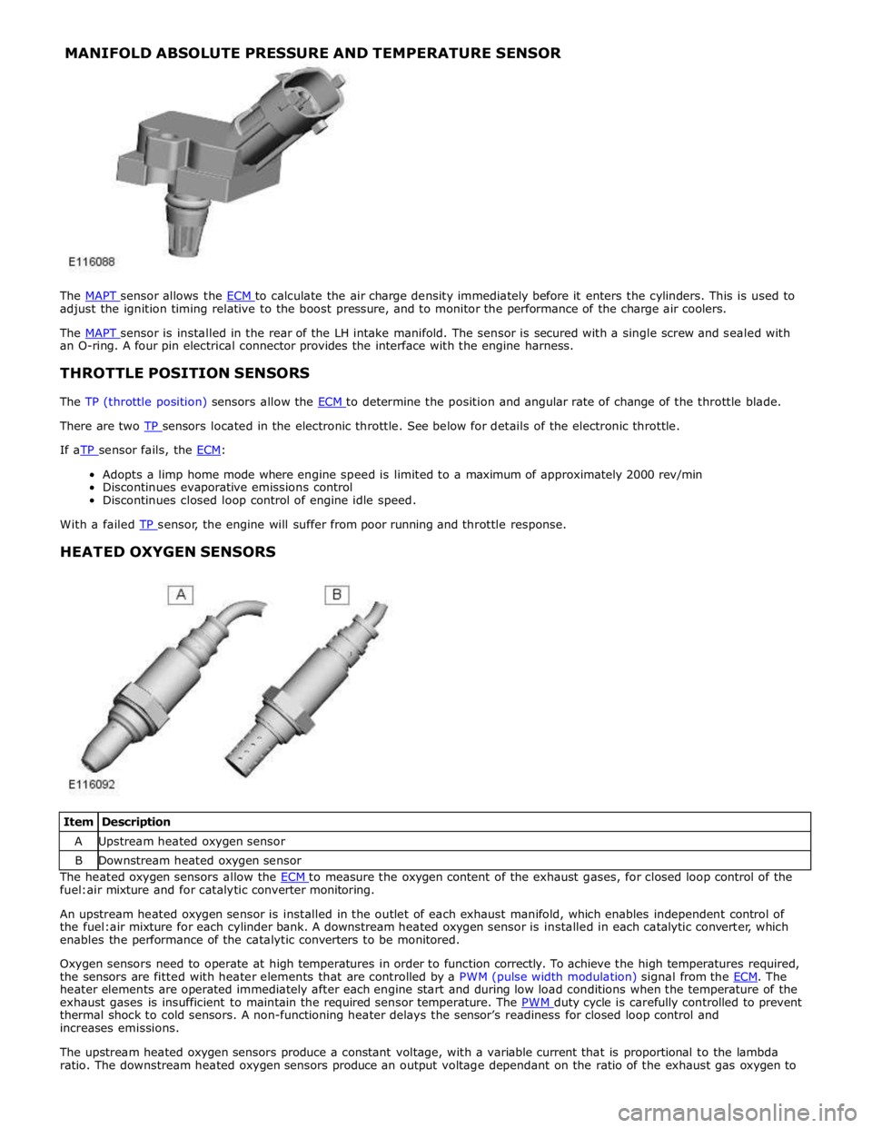
The MAPT sensor allows the ECM to calculate the air charge density immediately before it enters the cylinders. This is used to adjust the ignition timing relative to the boost pressure, and to monitor the performance of the charge air coolers.
The MAPT sensor is installed in the rear of the LH intake manifold. The sensor is secured with a single screw and sealed with an O-ring. A four pin electrical connector provides the interface with the engine harness.
THROTTLE POSITION SENSORS
The TP (throttle position) sensors allow the ECM to determine the position and angular rate of change of the throttle blade. There are two TP sensors located in the electronic throttle. See below for details of the electronic throttle. If aTP sensor fails, the ECM:
Adopts a limp home mode where engine speed is limited to a maximum of approximately 2000 rev/min
Discontinues evaporative emissions control
Discontinues closed loop control of engine idle speed.
With a failed TP sensor, the engine will suffer from poor running and throttle response.
HEATED OXYGEN SENSORS
Item Description A Upstream heated oxygen sensor B Downstream heated oxygen sensor The heated oxygen sensors allow the ECM to measure the oxygen content of the exhaust gases, for closed loop control of the fuel:air mixture and for catalytic converter monitoring.
An upstream heated oxygen sensor is installed in the outlet of each exhaust manifold, which enables independent control of
the fuel:air mixture for each cylinder bank. A downstream heated oxygen sensor is installed in each catalytic converter, which
enables the performance of the catalytic converters to be monitored.
Oxygen sensors need to operate at high temperatures in order to function correctly. To achieve the high temperatures required,
the sensors are fitted with heater elements that are controlled by a PWM (pulse width modulation) signal from the ECM. The heater elements are operated immediately after each engine start and during low load conditions when the temperature of the
exhaust gases is insufficient to maintain the required sensor temperature. The PWM duty cycle is carefully controlled to prevent thermal shock to cold sensors. A non-functioning heater delays the sensor’s readiness for closed loop control and
increases emissions.
The upstream heated oxygen sensors produce a constant voltage, with a variable current that is proportional to the lambda
ratio. The downstream heated oxygen sensors produce an output voltage dependant on the ratio of the exhaust gas oxygen to
Page 1366 of 3039
the period of rich to lean and lean to rich switching monitors the response rate of the upstream sensors.
Diagnosis of electrical faults is continually monitored in both the upstream and downstream sensors. This is achieved by
checking the signal against maximum and minimum threshold, for open and short circuit conditions.
If a heated oxygen sensor fails:
The ECM defaults to open loop fueling for the related cylinder bank The CO (carbon monoxide) and emissions content of the exhaust gases increases
The exhaust smells of rotten eggs (hydrogen sulphide).
With a failed heated oxygen sensor, the engine will suffer from unstable operation and reduced performance.
ACCELERATOR PEDAL POSITION SENSOR
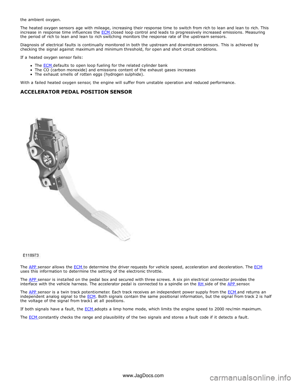
The APP sensor allows the ECM to determine the driver requests for vehicle speed, acceleration and deceleration. The ECM uses this information to determine the setting of the electronic throttle.
The APP sensor is installed on the pedal box and secured with three screws. A six pin electrical connector provides the interface with the vehicle harness. The accelerator pedal is connected to a spindle on the RH side of the APP sensor.
The APP sensor is a twin track potentiometer. Each track receives an independent power supply from the ECM and returns an independent analog signal to the ECM. Both signals contain the same positional information, but the signal from track 2 is half the voltage of the signal from track1 at all positions.
If both signals have a fault, the ECM adopts a limp home mode, which limits the engine speed to 2000 rev/min maximum. The ECM constantly checks the range and plausibility of the two signals and stores a fault code if it detects a fault. www.JagDocs.com
Page 1394 of 3039
Published: 11-May-2011
Electronic Engine Controls - V8 S/C 5.0L Petrol - Heated Oxygen Sensor
(HO2S) LH
Removal and Installation
Removal
NOTE: Removal steps in this procedure may contain installation details.
1. Refer to: Battery Disconnect and Connect (414-01 Battery, Mounting and Cables, General Procedures).
2. WARNING: Do not work on or under a vehicle supported only by a jack.
Always support the vehicle on safety stands.
Raise and support the vehicle.
3. Refer to: Air Deflector (501-02 Front End Body Panels, Removal and Installation).
4. Refer to: Catalytic Converter LH (309-00C Exhaust System - V8 5.0L Petrol/V8 S/C 5.0L Petrol, Removal and Installation).
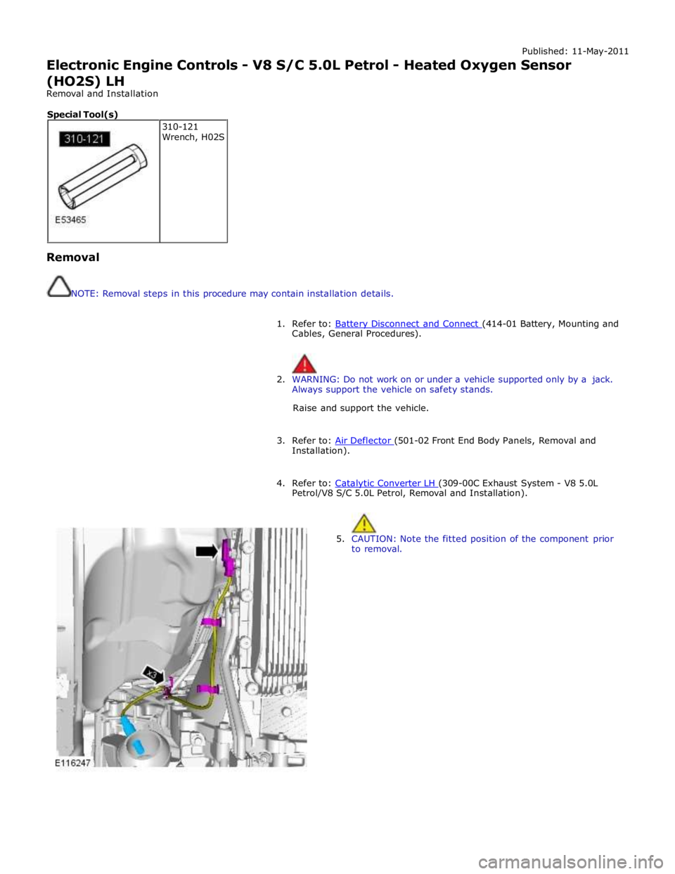
5. CAUTION: Note the fitted position of the component prior
to removal. 310-121
Wrench, H02S Special Tool(s)
Page 1396 of 3039
Published: 11-May-2011
Electronic Engine Controls - V8 S/C 5.0L Petrol - Heated Oxygen Sensor
(HO2S) RH
Removal and Installation
Removal
NOTE: Removal steps in this procedure may contain installation details.
1. Refer to: Battery Disconnect and Connect (414-01 Battery, Mounting and Cables, General Procedures).
2. WARNING: Do not work on or under a vehicle supported only by a jack.
Always support the vehicle on safety stands.
Raise and support the vehicle.
3. Refer to: Air Deflector (501-02 Front End Body Panels, Removal and Installation).
4. Refer to: Catalytic Converter RH (309-00C Exhaust System - V8 5.0L Petrol/V8 S/C 5.0L Petrol, Removal and Installation).
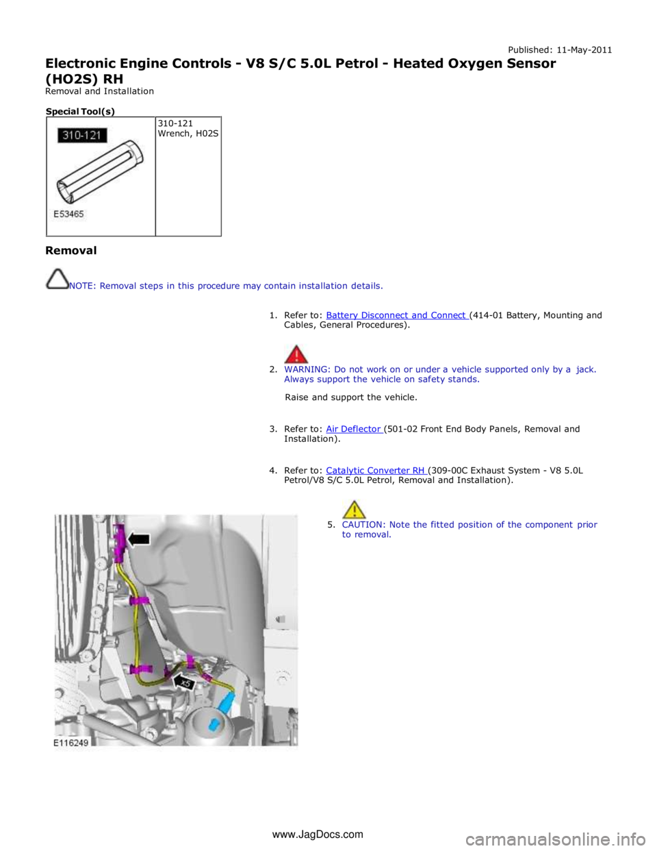
5. CAUTION: Note the fitted position of the component prior
to removal. 310-121
Wrench, H02S Special Tool(s) www.JagDocs.com
Page 1547 of 3039

Published: 28-Apr-2014
Exhaust System - V8 5.0L Petrol/V8 S/C 5.0L Petrol - Exhaust System - System Operation and Component Description
Description and Operation
CATALYTIC CONVERTERS System Operation
In the catalytic converters, the exhaust gases are passed through honeycombed ceramic elements coated with a special
surface treatment called 'washcoat'. The washcoat increases the surface area of the ceramic elements by a factor of
approximately 7000. On top of the washcoat is a coating containing palladium and rhodium, which are the active constituents
for converting harmful emissions into inert by-products. The palladium and rhodium add oxygen to the carbon monoxide and
the hydrocarbons in the exhaust gases, to convert them into carbon dioxide and water respectively.
SEMI-ACTIVE MUFFLER VALVE (5.0L SUPERCHARGER VEHICLES ONLY)
The semi-active muffler valve is operated by the pressure in the exhaust system. At low engine speeds the valve head is
closed or partially closed to provide a more refined noise quality. At higher engine speeds the increased pressure within the
exhaust system opens the valve head to provide a more sporting noise. This is achieved by the valve, which once open, allows
the exhaust gasses to by-pass the baffle tubes and plates in the rear silencer.
Component Description
FRONT SECTION - 4.2L NATURALLY ASPIRATED (NAS ONLY) - From 2010MY
The front section comprises two separate pipes, each incorporating a catalytic converter. Each catalytic converter has a welded
inlet pipe with a flange. The inlet pipe is flared into a cone which mates with the exhaust manifold. The flange has two holes
which locate on studs in the exhaust manifold and is secured with flanged nuts. Each catalytic converter is fitted with a pre
and post catalyst HO2S (heated oxygen sensor).
Each catalytic converter has a curved outlet pipe which mates with the respective inlet pipe for the applicable resonator on the
center section. The joint on each pipe is secured with a clamp.
FRONT SECTION - 5.0L NATURALLY ASPIRATED AND SUPERCHARGER - From 2010MY
The front section is common to both the naturally aspirated and supercharger vehicles. The front section comprises two
separate pipes each incorporating a catalytic converter. Each catalytic converter has a welded pipe with a flange, which is
flared into a cone which mates with the exhaust manifold. Each flange has two holes which locate on studs in the exhaust
manifold and are secured with nuts. Each catalytic converter is fitted with a mid catalyst HO2S. The mid catalyst HO2S is located in the catalytic converter.
NOTE: The pre catalyst HO2S is located in the exhaust manifold.
On vehicles from 2013MY, a post catalyst HO2S is located in the curved pipe from each catalytic converter.
A curved pipe from each catalytic converter locates into the resonator inlet pipes of the center section. The LH (left-hand) pipe
is fitted with a mass damper which absorbs resonance from the system.
REAR SECTION - 4.2L NATURALLY ASPIRATED (NAS ONLY) - From 2010MY
The 2 inlet pipes each connect into a separate resonator silencer. Each resonator silencer is cylindrical in shape and houses 2
perforated tubes separated by 2 baffle plates. Exhaust gasses exit each resonator silencer via an outlet pipe. The 2 outlet
pipes are joined together behind the resonators with a cross over pipe. Each pipe also has a welded hanger bracket which
allow the rear section to be supported on mounting rubbers. A further bracket is welded to each pipe which braces the 2 pipes
together.
The 2 rear silencers each have a welded inlet pipe which mate with the outlet pipes from the resonator silencers and are each
secured with a clamp. The inlet pipes each have a welded hanger bracket which support each rear silencer at the rear of the
vehicle on mounting rubbers. The fabricated rear silencers have 2 perforated tubes which are supported on 2 perforated baffle
plates. The exhaust gasses are expelled from the rear silencer via a single outlet pipe. The outlet pipe from each silencer has
a welded hanger bar which support the rear silencer on mounting rubbers. The outlet pipe is fitted with a welded outlet which
is covered with a polished stainless steel finisher which is part welded to the silencer.
REAR SECTION - 5.0L NATURALLY ASPIRATED - From 2010MY
The 2 pipes from the front section each connect into 2 short pipes on the center resonator box and are secured with clamps.
Two pipes from the resonator box split the system into 2 sections which each connect into another resonator. Each resonator
silencer houses perforated tubes separated by baffle plates. Exhaust gasses exit each resonator silencer via an outlet pipe.
The 2 outlet pipes are joined together behind the resonators with a cross over pipe. Each pipe also has a welded hanger
bracket which allow the rear section to be supported on mounting rubbers. A further bracket is welded to each pipe which
braces the 2 pipes together.
The 2 rear silencers each have a welded inlet pipe which mate with the outlet pipes from the cylindrical resonator silencers and
www.JagDocs.com