boot JAGUAR XFR 2010 1.G User Guide
[x] Cancel search | Manufacturer: JAGUAR, Model Year: 2010, Model line: XFR, Model: JAGUAR XFR 2010 1.GPages: 3039, PDF Size: 58.49 MB
Page 347 of 3039
60 Nm.
If the rear lower arm ball joint releases from the wheel
knuckle lower pivot, using no more than 60 Nm on the
special tool adjusting bolt, proceed to step 13.
If the rear lower arm ball joint does not release from
the wheel knuckle lower pivot, using no more than 60
Nm on the special tool adjusting bolt, proceed to step
12.
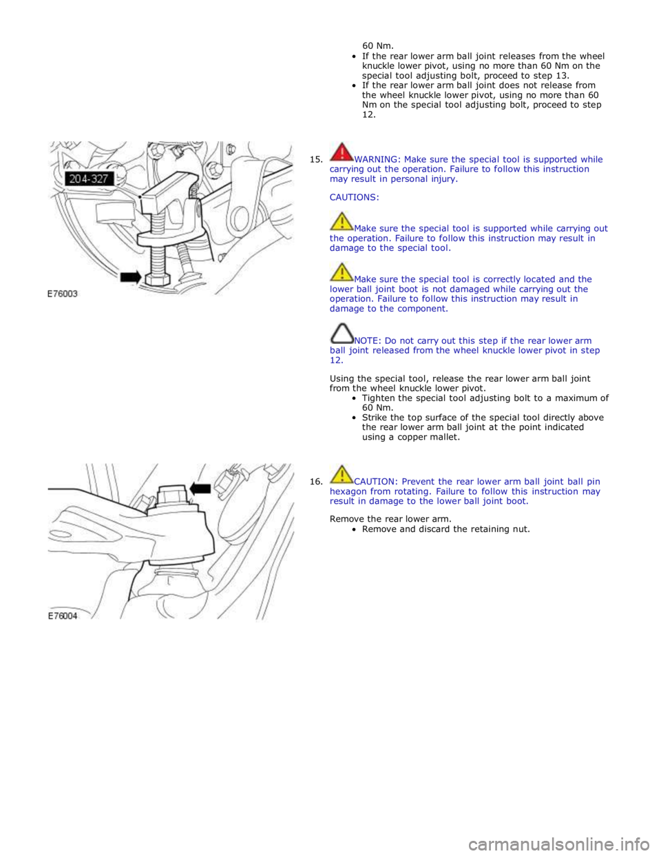
15. WARNING: Make sure the special tool is supported while
carrying out the operation. Failure to follow this instruction
may result in personal injury.
CAUTIONS:
Make sure the special tool is supported while carrying out
the operation. Failure to follow this instruction may result in
damage to the special tool.
Make sure the special tool is correctly located and the
lower ball joint boot is not damaged while carrying out the
operation. Failure to follow this instruction may result in
damage to the component.
NOTE: Do not carry out this step if the rear lower arm
ball joint released from the wheel knuckle lower pivot in step
12.
Using the special tool, release the rear lower arm ball joint
from the wheel knuckle lower pivot.
Tighten the special tool adjusting bolt to a maximum of
60 Nm.
Strike the top surface of the special tool directly above
the rear lower arm ball joint at the point indicated
using a copper mallet.
16. CAUTION: Prevent the rear lower arm ball joint ball pin
hexagon from rotating. Failure to follow this instruction may
result in damage to the lower ball joint boot.
Remove the rear lower arm.
Remove and discard the retaining nut.
Page 348 of 3039
Installation
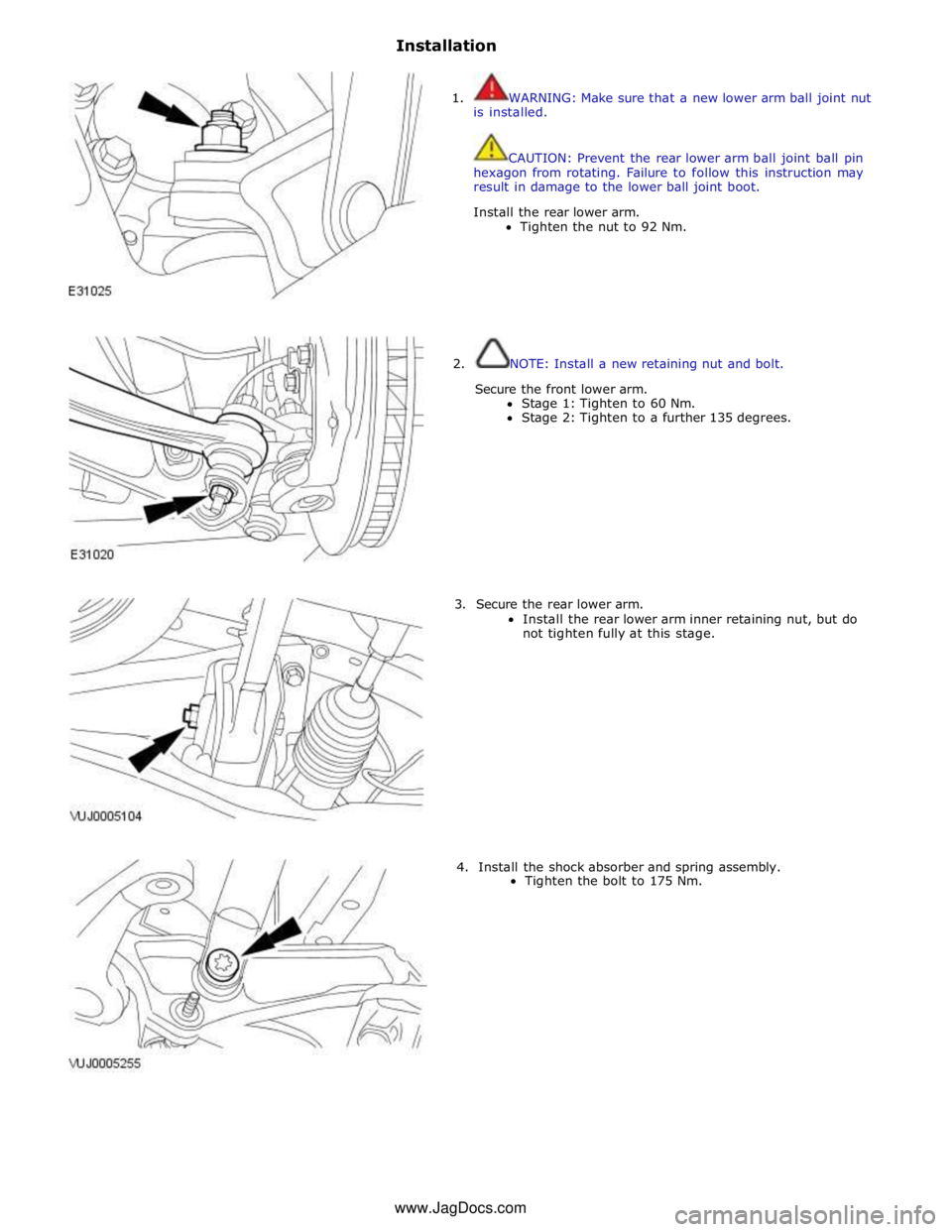
1. WARNING: Make sure that a new lower arm ball joint nut
is installed.
CAUTION: Prevent the rear lower arm ball joint ball pin
hexagon from rotating. Failure to follow this instruction may
result in damage to the lower ball joint boot.
Install the rear lower arm.
Tighten the nut to 92 Nm.
2. NOTE: Install a new retaining nut and bolt.
Secure the front lower arm.
Stage 1: Tighten to 60 Nm.
Stage 2: Tighten to a further 135 degrees.
3. Secure the rear lower arm.
Install the rear lower arm inner retaining nut, but do
not tighten fully at this stage.
4. Install the shock absorber and spring assembly.
Tighten the bolt to 175 Nm. www.JagDocs.com
Page 355 of 3039
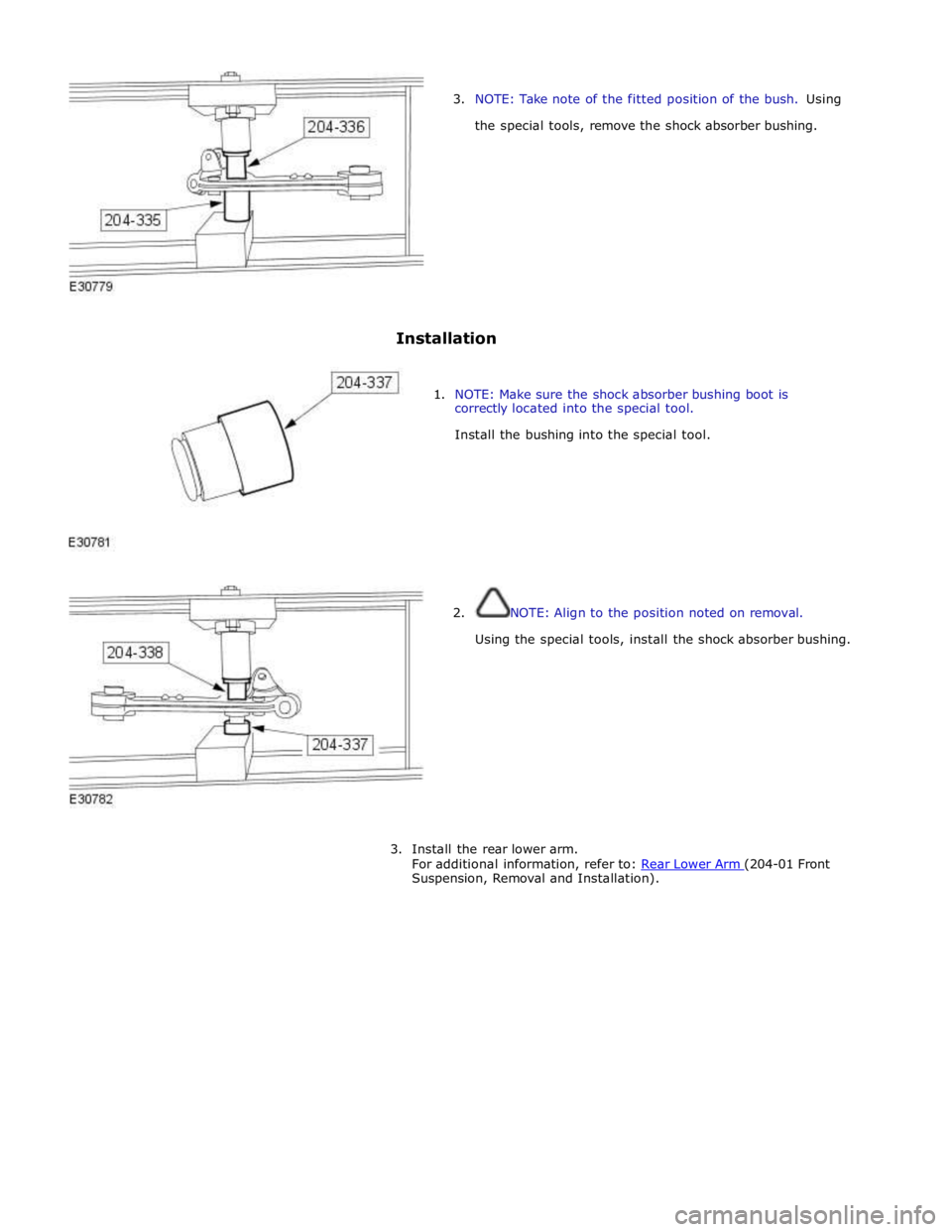
3. NOTE: Take note of the fitted position of the bush. Using
the special tools, remove the shock absorber bushing.
Installation
1. NOTE: Make sure the shock absorber bushing boot is
correctly located into the special tool.
Install the bushing into the special tool.
2. NOTE: Align to the position noted on removal.
Using the special tools, install the shock absorber bushing.
3. Install the rear lower arm.
For additional information, refer to: Rear Lower Arm (204-01 Front Suspension, Removal and Installation).
Page 575 of 3039
Rear Drive Halfshafts - Inner Constant Velocity (CV) Joint Boot
Removal and Installation
Removal Published: 11-May-2011
1. WARNING: Do not work on or under a vehicle supported only by a
jack. Always support the vehicle on safety stands.
Raise and support the vehicle.
2. Remove the rear halfshaft.
For additional information, refer to: Rear Halfshaft - TDV6 3.0L Diesel /V8 5.0L Petrol/V8 S/C 5.0L Petrol (205-05 Rear Drive Halfshafts, Removal and Installation).
3. CAUTION: Use suitable protective covers to protect the halfshaft.
Using a suitable clamp, secure the rear halfshaft.
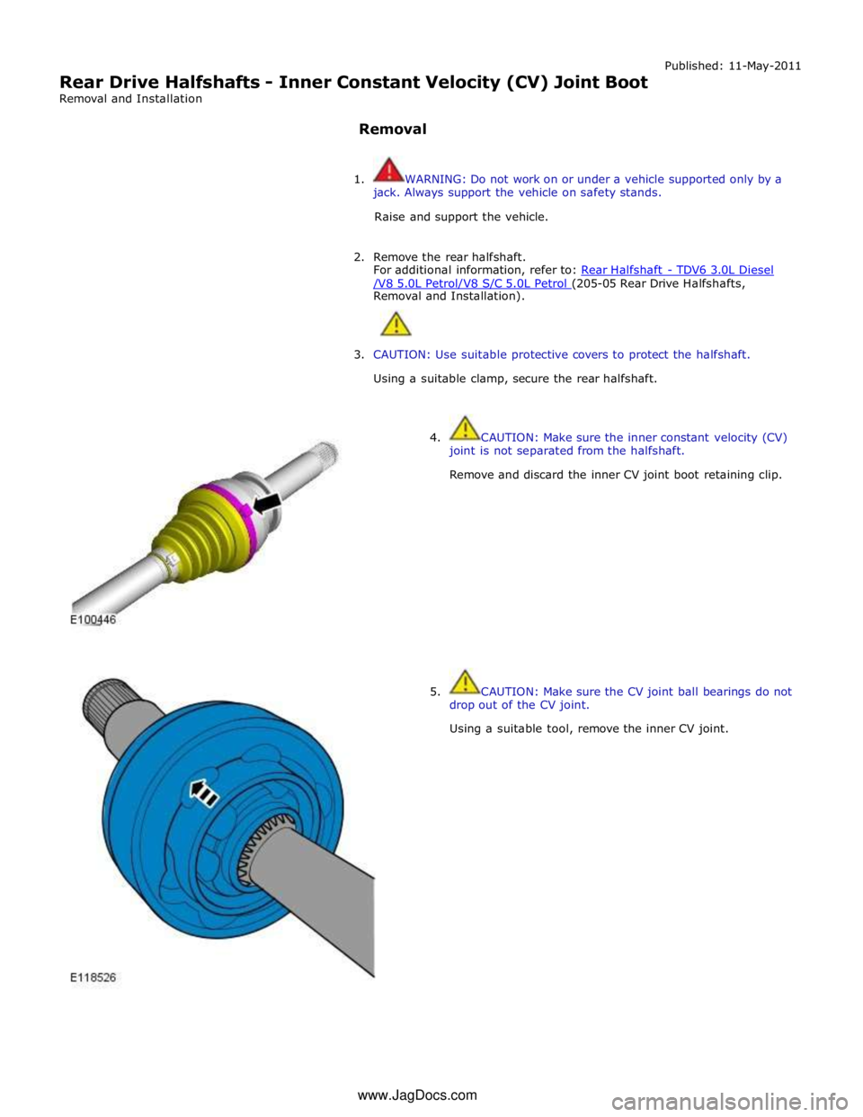
4. CAUTION: Make sure the inner constant velocity (CV)
joint is not separated from the halfshaft.
Remove and discard the inner CV joint boot retaining clip.
5. CAUTION: Make sure the CV joint ball bearings do not
drop out of the CV joint.
Using a suitable tool, remove the inner CV joint. www.JagDocs.com
Page 576 of 3039
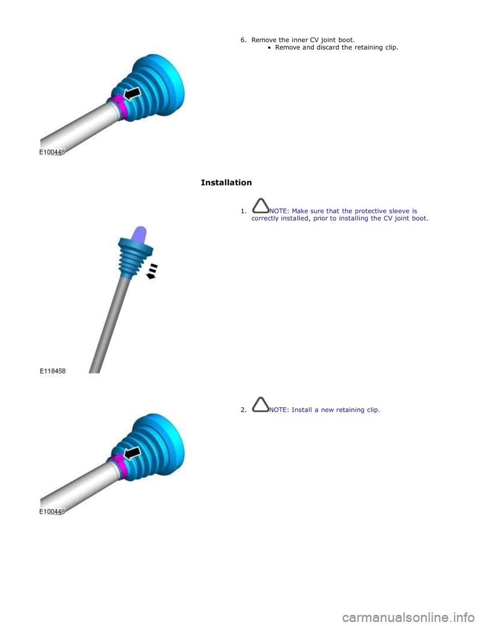
6. Remove the inner CV joint boot.
Remove and discard the retaining clip.
Installation
1. NOTE: Make sure that the protective sleeve is
correctly installed, prior to installing the CV joint boot.
2. NOTE: Install a new retaining clip.
Page 577 of 3039
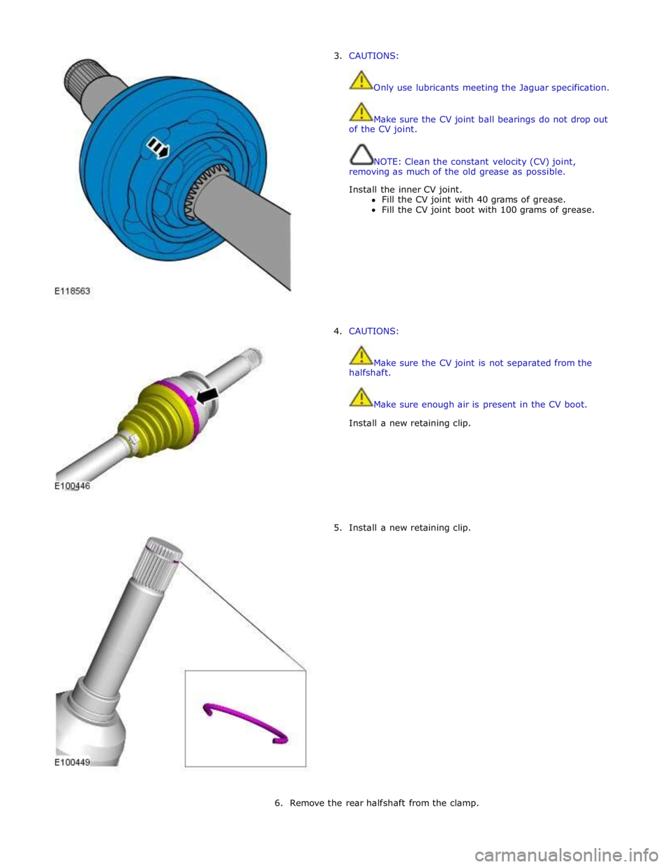
3. CAUTIONS:
Only use lubricants meeting the Jaguar specification.
Make sure the CV joint ball bearings do not drop out
of the CV joint.
NOTE: Clean the constant velocity (CV) joint,
removing as much of the old grease as possible.
Install the inner CV joint.
Fill the CV joint with 40 grams of grease.
Fill the CV joint boot with 100 grams of grease.
4. CAUTIONS:
Make sure the CV joint is not separated from the
halfshaft.
Make sure enough air is present in the CV boot.
Install a new retaining clip.
5. Install a new retaining clip.
6. Remove the rear halfshaft from the clamp.
Page 579 of 3039
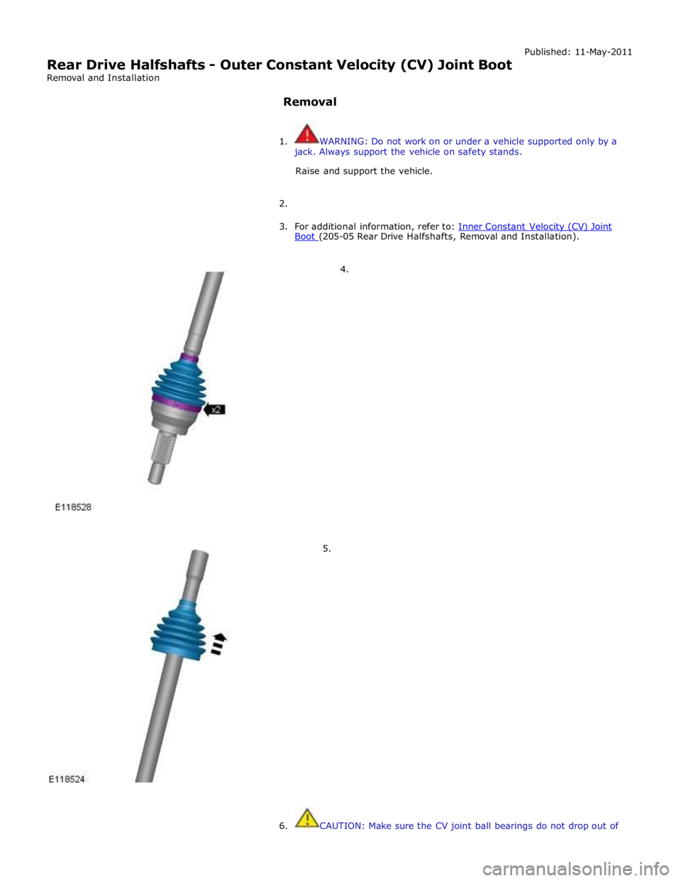
Rear Drive Halfshafts - Outer Constant Velocity (CV) Joint Boot
Removal and Installation
Removal Published: 11-May-2011
1. WARNING: Do not work on or under a vehicle supported only by a
jack. Always support the vehicle on safety stands.
Raise and support the vehicle.
2.
3. For additional information, refer to: Inner Constant Velocity (CV) Joint Boot (205-05 Rear Drive Halfshafts, Removal and Installation).
4.
5.
6. CAUTION: Make sure the CV joint ball bearings do not drop out of
Page 580 of 3039
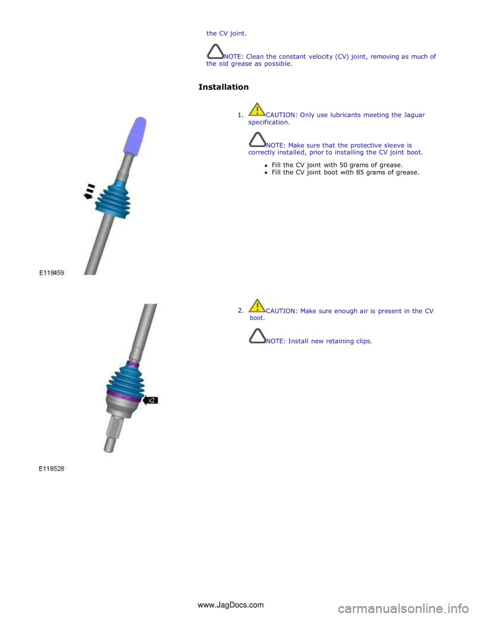
the CV joint.
NOTE: Clean the constant velocity (CV) joint, removing as much of
the old grease as possible.
Installation
1. CAUTION: Only use lubricants meeting the Jaguar
specification.
NOTE: Make sure that the protective sleeve is
correctly installed, prior to installing the CV joint boot.
Fill the CV joint with 50 grams of grease.
Fill the CV joint boot with 85 grams of grease.
2. boot.
CAUTION: Make sure enough air is present in the CV
NOTE: Install new retaining clips. www.JagDocs.com
Page 718 of 3039
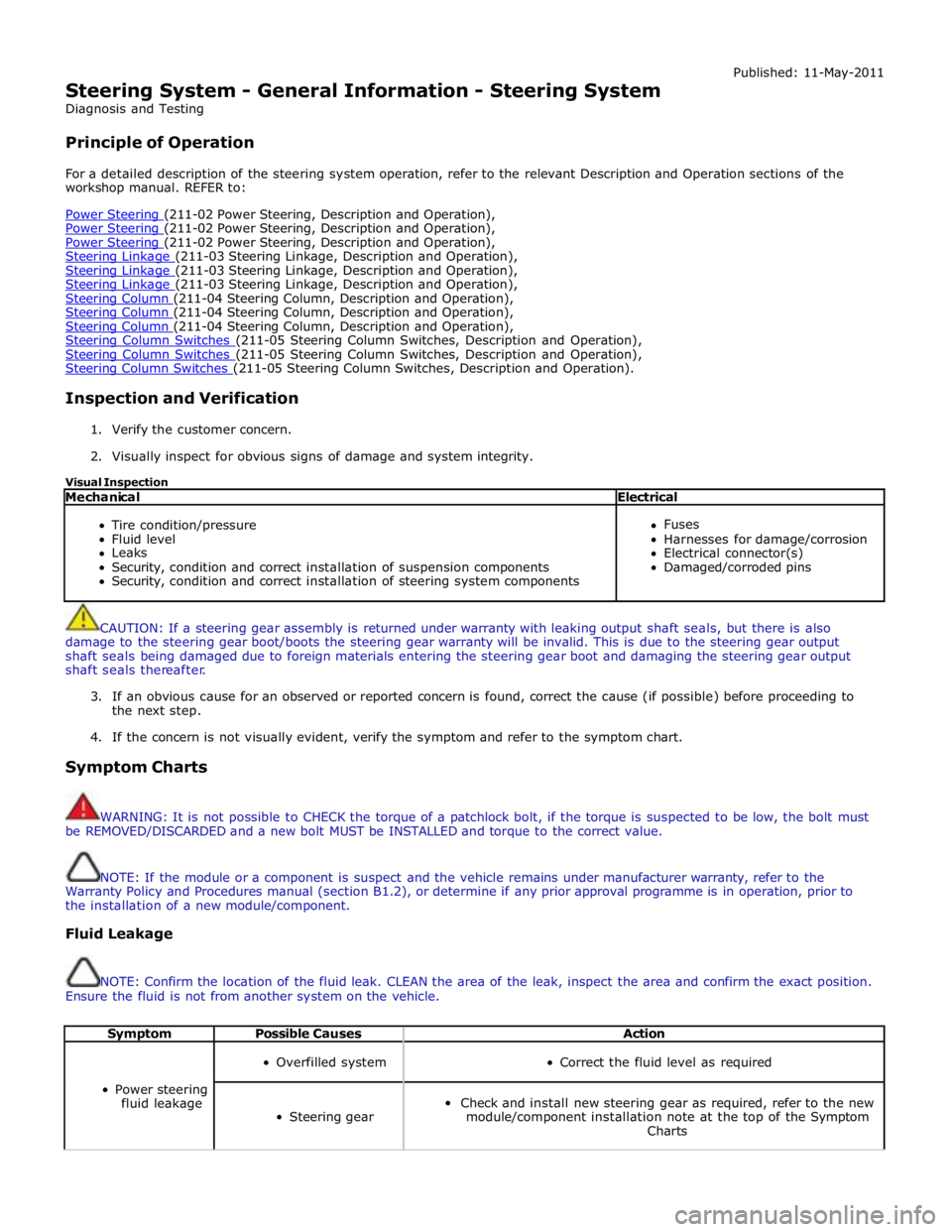
Steering System - General Information - Steering System
Diagnosis and Testing
Principle of Operation Published: 11-May-2011
For a detailed description of the steering system operation, refer to the relevant Description and Operation sections of the
workshop manual. REFER to:
Power Steering (211-02 Power Steering, Description and Operation), Power Steering (211-02 Power Steering, Description and Operation), Power Steering (211-02 Power Steering, Description and Operation), Steering Linkage (211-03 Steering Linkage, Description and Operation), Steering Linkage (211-03 Steering Linkage, Description and Operation), Steering Linkage (211-03 Steering Linkage, Description and Operation), Steering Column (211-04 Steering Column, Description and Operation), Steering Column (211-04 Steering Column, Description and Operation), Steering Column (211-04 Steering Column, Description and Operation), Steering Column Switches (211-05 Steering Column Switches, Description and Operation), Steering Column Switches (211-05 Steering Column Switches, Description and Operation), Steering Column Switches (211-05 Steering Column Switches, Description and Operation).
Inspection and Verification
1. Verify the customer concern.
2. Visually inspect for obvious signs of damage and system integrity.
Visual Inspection
Mechanical Electrical
Tire condition/pressure
Fluid level
Leaks
Security, condition and correct installation of suspension components
Security, condition and correct installation of steering system components
Fuses
Harnesses for damage/corrosion
Electrical connector(s)
Damaged/corroded pins
CAUTION: If a steering gear assembly is returned under warranty with leaking output shaft seals, but there is also
damage to the steering gear boot/boots the steering gear warranty will be invalid. This is due to the steering gear output
shaft seals being damaged due to foreign materials entering the steering gear boot and damaging the steering gear output
shaft seals thereafter.
3. If an obvious cause for an observed or reported concern is found, correct the cause (if possible) before proceeding to
the next step.
4. If the concern is not visually evident, verify the symptom and refer to the symptom chart.
Symptom Charts
WARNING: It is not possible to CHECK the torque of a patchlock bolt, if the torque is suspected to be low, the bolt must
be REMOVED/DISCARDED and a new bolt MUST be INSTALLED and torque to the correct value.
NOTE: If the module or a component is suspect and the vehicle remains under manufacturer warranty, refer to the
Warranty Policy and Procedures manual (section B1.2), or determine if any prior approval programme is in operation, prior to
the installation of a new module/component.
Fluid Leakage
NOTE: Confirm the location of the fluid leak. CLEAN the area of the leak, inspect the area and confirm the exact position.
Ensure the fluid is not from another system on the vehicle.
Symptom Possible Causes Action
Power steering
fluid leakage
Overfilled system
Correct the fluid level as required
Steering gear
Check and install new steering gear as required, refer to the new
module/component installation note at the top of the Symptom
Charts
Page 723 of 3039
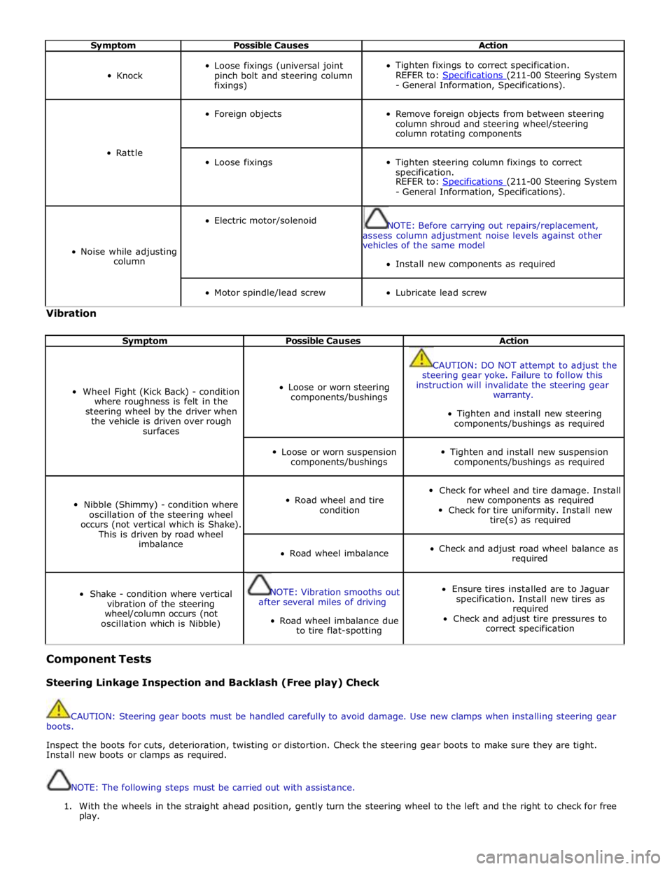
Symptom Possible Causes Action
Knock
Loose fixings (universal joint
pinch bolt and steering column
fixings)
Tighten fixings to correct specification.
REFER to: Specifications (211-00 Steering System - General Information, Specifications).
Rattle
Foreign objects
Remove foreign objects from between steering
column shroud and steering wheel/steering
column rotating components
Loose fixings
Tighten steering column fixings to correct
specification.
REFER to: Specifications (211-00 Steering System - General Information, Specifications).
Noise while adjusting
column
Electric motor/solenoid
NOTE: Before carrying out repairs/replacement,
assess column adjustment noise levels against other
vehicles of the same model
Install new components as required
Motor spindle/lead screw
Lubricate lead screw Vibration
Symptom Possible Causes Action
Wheel Fight (Kick Back) - condition
where roughness is felt in the
steering wheel by the driver when
the vehicle is driven over rough
surfaces
Loose or worn steering
components/bushings
CAUTION: DO NOT attempt to adjust the
steering gear yoke. Failure to follow this
instruction will invalidate the steering gear
warranty.
Tighten and install new steering
components/bushings as required
Loose or worn suspension
components/bushings
Tighten and install new suspension
components/bushings as required
Nibble (Shimmy) - condition where
oscillation of the steering wheel
occurs (not vertical which is Shake).
This is driven by road wheel
imbalance
Road wheel and tire
condition
Check for wheel and tire damage. Install
new components as required
Check for tire uniformity. Install new
tire(s) as required
Road wheel imbalance
Check and adjust road wheel balance as
required
Shake - condition where vertical
vibration of the steering
wheel/column occurs (not
oscillation which is Nibble)
NOTE: Vibration smooths out
after several miles of driving
Road wheel imbalance due
to tire flat-spotting
Ensure tires installed are to Jaguar
specification. Install new tires as
required
Check and adjust tire pressures to
correct specification Component Tests
Steering Linkage Inspection and Backlash (Free play) Check
CAUTION: Steering gear boots must be handled carefully to avoid damage. Use new clamps when installing steering gear
boots.
Inspect the boots for cuts, deterioration, twisting or distortion. Check the steering gear boots to make sure they are tight.
Install new boots or clamps as required.
NOTE: The following steps must be carried out with assistance.
1. With the wheels in the straight ahead position, gently turn the steering wheel to the left and the right to check for free
play.