boot JAGUAR XFR 2010 1.G Owner's Manual
[x] Cancel search | Manufacturer: JAGUAR, Model Year: 2010, Model line: XFR, Model: JAGUAR XFR 2010 1.GPages: 3039, PDF Size: 58.49 MB
Page 745 of 3039
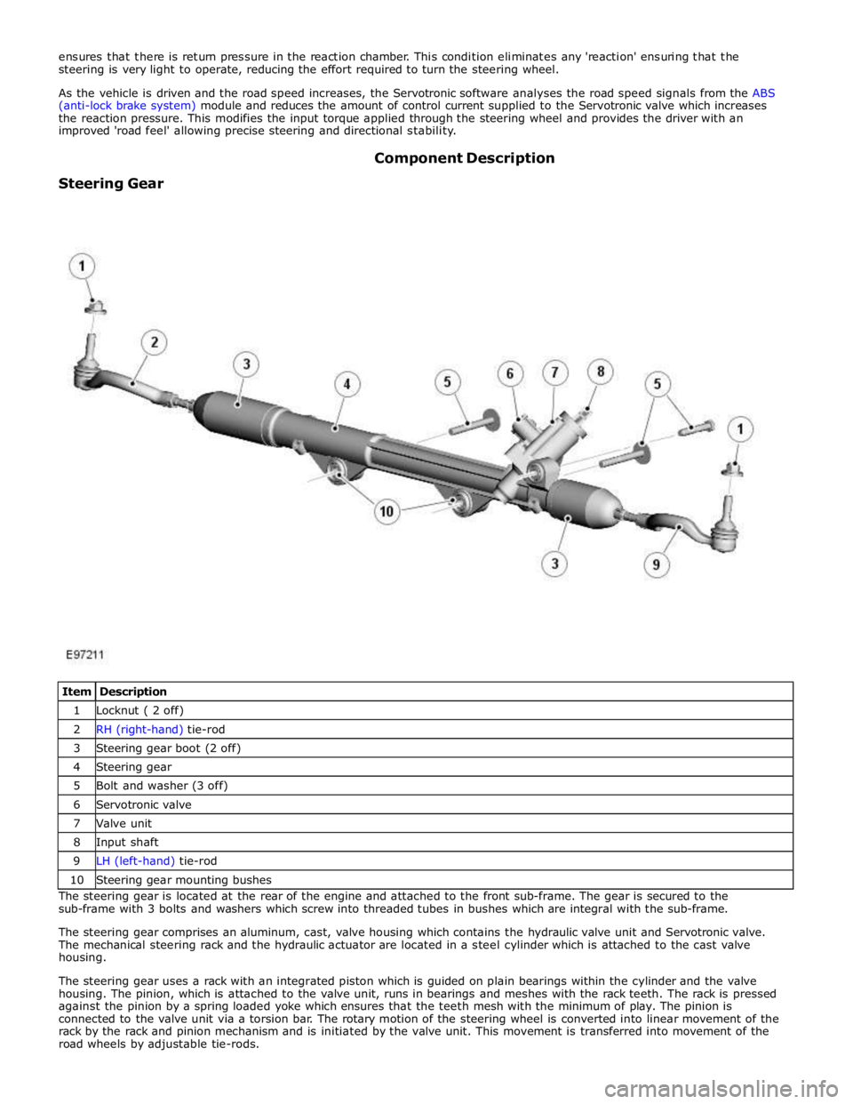
1 Locknut ( 2 off) 2 RH (right-hand) tie-rod 3 Steering gear boot (2 off) 4 Steering gear 5 Bolt and washer (3 off) 6 Servotronic valve 7 Valve unit 8 Input shaft 9 LH (left-hand) tie-rod 10 Steering gear mounting bushes The steering gear is located at the rear of the engine and attached to the front sub-frame. The gear is secured to the
sub-frame with 3 bolts and washers which screw into threaded tubes in bushes which are integral with the sub-frame.
The steering gear comprises an aluminum, cast, valve housing which contains the hydraulic valve unit and Servotronic valve.
The mechanical steering rack and the hydraulic actuator are located in a steel cylinder which is attached to the cast valve
housing.
The steering gear uses a rack with an integrated piston which is guided on plain bearings within the cylinder and the valve
housing. The pinion, which is attached to the valve unit, runs in bearings and meshes with the rack teeth. The rack is pressed
against the pinion by a spring loaded yoke which ensures that the teeth mesh with the minimum of play. The pinion is
connected to the valve unit via a torsion bar. The rotary motion of the steering wheel is converted into linear movement of the
rack by the rack and pinion mechanism and is initiated by the valve unit. This movement is transferred into movement of the
road wheels by adjustable tie-rods.
Page 769 of 3039
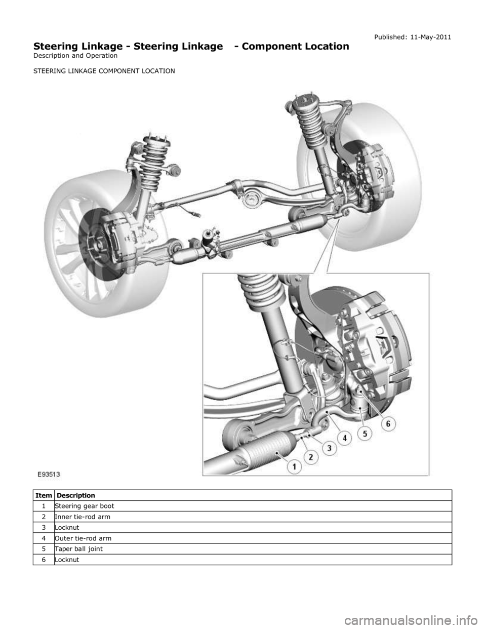
1 Steering gear boot 2 Inner tie-rod arm 3 Locknut 4 Outer tie-rod arm 5 Taper ball joint 6 Locknut
Page 770 of 3039

Steering Linkage - Steering Linkage - Overview
Description and Operation
OVERVIEW Published: 11-May-2011
The steering linkage comprises the tie rod which provides the connection between the steering gear and the front wheel
knuckle. Each end of the steering gear has a threaded hole which provides for the fitment of the inner tie rods. The external
ends of the inner tie rods are sealed with boots to prevent the ingress of dirt and moisture into the steering gear.
Page 783 of 3039
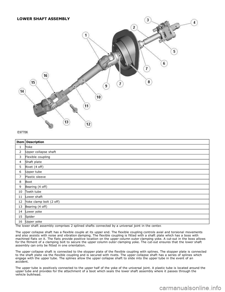
1 Yoke 2 Upper collapse shaft 3 Flexible coupling 4 Shaft plate 5 Rivet (4 off) 6 Upper tube 7 Plastic sleeve 8 Boot 9 Bearing (4 off) 10 Teeth tube 11 Lower shaft 12 Yoke clamp bolt (2 off) 13 Bearing (4 off) 14 Lower yoke 15 Spider 16 Upper yoke The lower shaft assembly comprises 2 splined shafts connected by a universal joint in the center.
The upper collapse shaft has a flexible couple at its upper end. The flexible coupling controls axial and torsional movements
and also assists with noise and vibration damping. The flexible coupling is fitted with a shaft plate which has a boss with
machined flats on it. The flats provide positive location on the upper column outer clamping yoke. A cut-out in the boss allows
for the fitment of a clamping bolt to secure the upper column outer clamping yoke. The cut-out ensures that the lower shaft
assembly can only be fitted in one orientation.
The upper collapse shaft is connected to the stopper plate of the flexible coupling with splines. The stopper plate is connected
to the shaft plate via the flexible coupling and is secured with rivets. The upper collapse shaft has a series of splines which
engage with the upper tube. The splines allow the upper collapse shaft to slide into the upper tube in the event of an
accident.
The upper tube is positively connected to the upper half of the yoke of the universal joint. A plastic tube is located around the
upper tube and provides for the attachment of a boot which seals the lower shaft assembly where it passes through the
vehicle bulkhead. LOWER SHAFT ASSEMBLY
Page 1187 of 3039
Published: 11-May-2011
Fuel Charging and Controls - V8 S/C 5.0L Petrol - Fuel Charging and Controls
Diagnosis and Testing
Principles of Operation
For a detailed description of the fuel charging and controls system and operation, refer to the relevant Description and
Operation section of the workshop manual. REFER to:
Fuel Charging and Controls (303-04D Fuel Charging and Controls - V8 5.0L Petrol, Description and Operation), Fuel Charging and Controls (303-04D Fuel Charging and Controls - V8 5.0L Petrol, Description and Operation), Fuel Charging and Controls (303-04D Fuel Charging and Controls - V8 5.0L Petrol, Description and Operation), Fuel Charging and Controls (303-04E Fuel Charging and Controls - V8 S/C 5.0L Petrol, Description and Operation), Fuel Charging and Controls (303-04E Fuel Charging and Controls - V8 S/C 5.0L Petrol, Description and Operation), Fuel Charging and Controls (303-04E Fuel Charging and Controls - V8 S/C 5.0L Petrol, Description and Operation).
Inspection and Verification
CAUTION: Diagnosis by substitution from a donor vehicle is NOT acceptable. Substitution of control modules does not
guarantee confirmation of a fault and may also cause additional faults in the vehicle being checked and/or the donor vehicle.
NOTE: Check and rectify basic faults before beginning diagnostic routines involving pinpoint tests.
1. Verify the customer concern.
2. Visually inspect for obvious signs of mechanical or electrical damage.
Visual Inspection
Mechanical Electrical
Fuel level
Fuel leaks
Damaged fuel lines
Damaged push connect fittings
Fuel contamination/grade/quality
Throttle body
Damaged fuel tank filler pipe cap
Damaged fuel tank filler pipe
Fuses
Loose or corroded electrical connectors
Harnesses
Sensor(s)
Engine Control Module (ECM)
3. If an obvious cause for an observed or reported concern is found, correct the cause (if possible) before proceeding to
the next step.
4. If the cause is not visually evident, verify the symptom and refer to the Symptom Chart, alternatively check for
Diagnostic Trouble Codes (DTCs) and refer to the DTC Index.
Symptom Chart
Symptom Possible Causes Action Engine cranks, but does not
fire
Engine breather system
disconnected/restricted
Ignition system
Fuel system
Electronic engine control Ensure the engine breather system is free from restriction
and is correctly installed. Check for ignition system, fuel
system and electronic engine control DTCs and refer to the
relevant DTC Index Engine cranks and fires, but
will not start
Evaporative emissions purge
valve
Fuel pump
Spark plugs
HT short to ground (tracking)
check rubber boots for
cracks/damage
Ignition system Check for evaporative emissions, fuel system and ignition
system related DTCs and refer to the relevant DTC Index Difficult cold start
Engine coolant level/anti-
freeze content
Battery
Electronic engine controls
Exhaust Gas Recirculation
(EGR) valve stuck open
Fuel pump Check the engine coolant level and condition. Ensure the
battery is in a fully charged and serviceable condition.
Check for electronic engine controls, engine emissions, fuel
system and evaporative emissions system related DTCs
and refer to the relevant DTC Index www.JagDocs.com
Page 1276 of 3039
Published: 11-May-2011
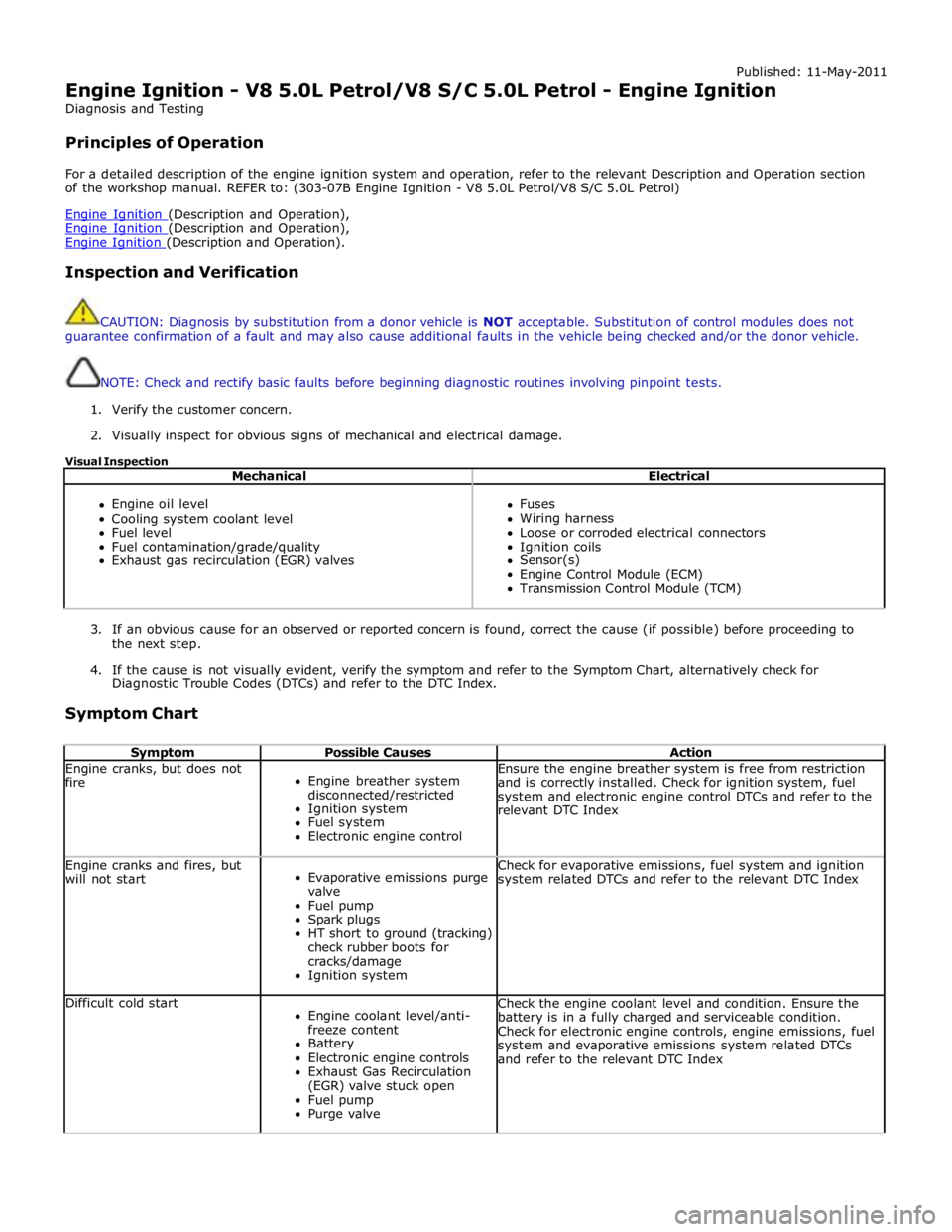
Engine Ignition - V8 5.0L Petrol/V8 S/C 5.0L Petrol - Engine Ignition
Diagnosis and Testing
Principles of Operation
For a detailed description of the engine ignition system and operation, refer to the relevant Description and Operation section
of the workshop manual. REFER to: (303-07B Engine Ignition - V8 5.0L Petrol/V8 S/C 5.0L Petrol)
Engine Ignition (Description and Operation), Engine Ignition (Description and Operation), Engine Ignition (Description and Operation).
Inspection and Verification
CAUTION: Diagnosis by substitution from a donor vehicle is NOT acceptable. Substitution of control modules does not
guarantee confirmation of a fault and may also cause additional faults in the vehicle being checked and/or the donor vehicle.
NOTE: Check and rectify basic faults before beginning diagnostic routines involving pinpoint tests.
1. Verify the customer concern.
2. Visually inspect for obvious signs of mechanical and electrical damage.
Visual Inspection
Mechanical Electrical
Engine oil level
Cooling system coolant level
Fuel level
Fuel contamination/grade/quality
Exhaust gas recirculation (EGR) valves
Fuses
Wiring harness
Loose or corroded electrical connectors
Ignition coils
Sensor(s)
Engine Control Module (ECM)
Transmission Control Module (TCM)
3. If an obvious cause for an observed or reported concern is found, correct the cause (if possible) before proceeding to
the next step.
4. If the cause is not visually evident, verify the symptom and refer to the Symptom Chart, alternatively check for
Diagnostic Trouble Codes (DTCs) and refer to the DTC Index.
Symptom Chart
Symptom Possible Causes Action Engine cranks, but does not
fire
Engine breather system
disconnected/restricted
Ignition system
Fuel system
Electronic engine control Ensure the engine breather system is free from restriction
and is correctly installed. Check for ignition system, fuel
system and electronic engine control DTCs and refer to the
relevant DTC Index Engine cranks and fires, but
will not start
Evaporative emissions purge
valve
Fuel pump
Spark plugs
HT short to ground (tracking)
check rubber boots for
cracks/damage
Ignition system Check for evaporative emissions, fuel system and ignition
system related DTCs and refer to the relevant DTC Index Difficult cold start
Engine coolant level/anti-
freeze content
Battery
Electronic engine controls
Exhaust Gas Recirculation
(EGR) valve stuck open
Fuel pump
Purge valve Check the engine coolant level and condition. Ensure the
battery is in a fully charged and serviceable condition.
Check for electronic engine controls, engine emissions, fuel
system and evaporative emissions system related DTCs
and refer to the relevant DTC Index
Page 1596 of 3039
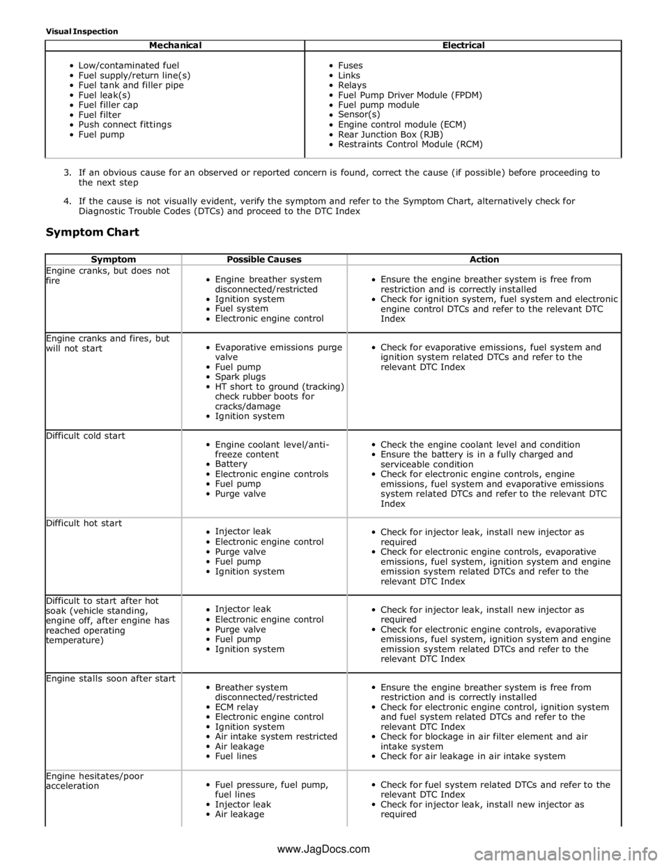
Visual Inspection
Mechanical Electrical
Low/contaminated fuel
Fuel supply/return line(s)
Fuel tank and filler pipe
Fuel leak(s)
Fuel filler cap
Fuel filter
Push connect fittings
Fuel pump
Fuses
Links
Relays
Fuel Pump Driver Module (FPDM)
Fuel pump module
Sensor(s)
Engine control module (ECM)
Rear Junction Box (RJB)
Restraints Control Module (RCM)
3. If an obvious cause for an observed or reported concern is found, correct the cause (if possible) before proceeding to
the next step
4. If the cause is not visually evident, verify the symptom and refer to the Symptom Chart, alternatively check for
Diagnostic Trouble Codes (DTCs) and proceed to the DTC Index
Symptom Chart
Symptom Possible Causes Action Engine cranks, but does not
fire
Engine breather system
disconnected/restricted
Ignition system
Fuel system
Electronic engine control
Ensure the engine breather system is free from
restriction and is correctly installed
Check for ignition system, fuel system and electronic
engine control DTCs and refer to the relevant DTC
Index Engine cranks and fires, but
will not start
Evaporative emissions purge
valve
Fuel pump
Spark plugs
HT short to ground (tracking)
check rubber boots for
cracks/damage
Ignition system
Check for evaporative emissions, fuel system and
ignition system related DTCs and refer to the
relevant DTC Index Difficult cold start
Engine coolant level/anti-
freeze content
Battery
Electronic engine controls
Fuel pump
Purge valve
Check the engine coolant level and condition
Ensure the battery is in a fully charged and
serviceable condition
Check for electronic engine controls, engine
emissions, fuel system and evaporative emissions
system related DTCs and refer to the relevant DTC
Index Difficult hot start
Injector leak
Electronic engine control
Purge valve
Fuel pump
Ignition system
Check for injector leak, install new injector as
required
Check for electronic engine controls, evaporative
emissions, fuel system, ignition system and engine
emission system related DTCs and refer to the
relevant DTC Index Difficult to start after hot
soak (vehicle standing,
engine off, after engine has
reached operating
temperature)
Injector leak
Electronic engine control
Purge valve
Fuel pump
Ignition system
Check for injector leak, install new injector as
required
Check for electronic engine controls, evaporative
emissions, fuel system, ignition system and engine
emission system related DTCs and refer to the
relevant DTC Index Engine stalls soon after start
Breather system
disconnected/restricted
ECM relay
Electronic engine control
Ignition system
Air intake system restricted
Air leakage
Fuel lines
Ensure the engine breather system is free from
restriction and is correctly installed
Check for electronic engine control, ignition system
and fuel system related DTCs and refer to the
relevant DTC Index
Check for blockage in air filter element and air
intake system
Check for air leakage in air intake system Engine hesitates/poor
acceleration
Fuel pressure, fuel pump,
fuel lines
Injector leak
Air leakage
Check for fuel system related DTCs and refer to the
relevant DTC Index
Check for injector leak, install new injector as
required www.JagDocs.com
Page 1827 of 3039
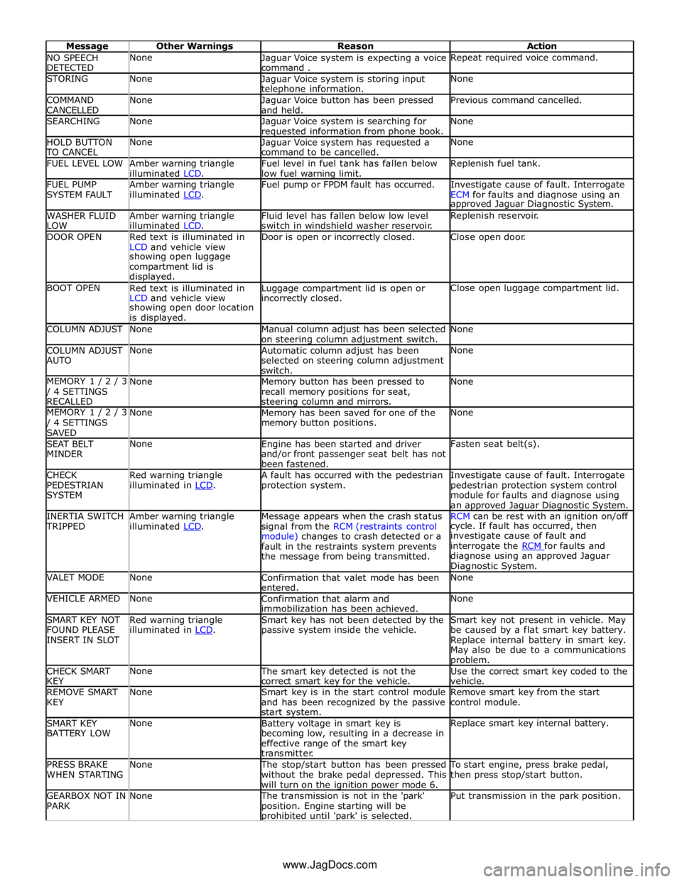
NO SPEECH
DETECTED None
Jaguar Voice system is expecting a voice
command . Repeat required voice command. STORING None
Jaguar Voice system is storing input telephone information. None COMMAND
CANCELLED None
Jaguar Voice button has been pressed
and held. Previous command cancelled. SEARCHING None
Jaguar Voice system is searching for requested information from phone book. None HOLD BUTTON TO CANCEL None
Jaguar Voice system has requested a
command to be cancelled. None FUEL LEVEL LOW
Amber warning triangle
illuminated LCD. Fuel level in fuel tank has fallen below
low fuel warning limit. Replenish fuel tank. FUEL PUMP
SYSTEM FAULT Amber warning triangle
illuminated LCD. Fuel pump or FPDM fault has occurred.
Investigate cause of fault. Interrogate
ECM for faults and diagnose using an approved Jaguar Diagnostic System. WASHER FLUID
LOW Amber warning triangle
illuminated LCD. Fluid level has fallen below low level
switch in windshield washer reservoir. Replenish reservoir. DOOR OPEN
Red text is illuminated in
LCD and vehicle view Door is open or incorrectly closed. Close open door. showing open luggage
compartment lid is
displayed. BOOT OPEN
Red text is illuminated in
LCD and vehicle view Luggage compartment lid is open or incorrectly closed. Close open luggage compartment lid. showing open door location
is displayed. COLUMN ADJUST None
Manual column adjust has been selected
on steering column adjustment switch. None COLUMN ADJUST
AUTO None
Automatic column adjust has been
selected on steering column adjustment
switch. None MEMORY 1 / 2 / 3 / 4 SETTINGS
RECALLED None
Memory button has been pressed to
recall memory positions for seat, steering column and mirrors. None MEMORY 1 / 2 / 3 / 4 SETTINGS
SAVED None
Memory has been saved for one of the
memory button positions. None SEAT BELT
MINDER None
Engine has been started and driver
and/or front passenger seat belt has not
been fastened. Fasten seat belt(s). CHECK
PEDESTRIAN
SYSTEM Red warning triangle
illuminated in LCD. A fault has occurred with the pedestrian
protection system. Investigate cause of fault. Interrogate
pedestrian protection system control
module for faults and diagnose using
an approved Jaguar Diagnostic System. INERTIA SWITCH TRIPPED Amber warning triangle
illuminated LCD. Message appears when the crash status
signal from the RCM (restraints control
module) changes to crash detected or a
fault in the restraints system prevents
the message from being transmitted. RCM can be rest with an ignition on/off cycle. If fault has occurred, then
investigate cause of fault and
interrogate the RCM for faults and diagnose using an approved Jaguar
Diagnostic System. VALET MODE None
Confirmation that valet mode has been
entered. None VEHICLE ARMED None
Confirmation that alarm and
immobilization has been achieved. None SMART KEY NOT
FOUND PLEASE
INSERT IN SLOT Red warning triangle
illuminated in LCD. Smart key has not been detected by the
passive system inside the vehicle. Smart key not present in vehicle. May
be caused by a flat smart key battery.
Replace internal battery in smart key.
May also be due to a communications problem. CHECK SMART
KEY None The smart key detected is not the
correct smart key for the vehicle. Use the correct smart key coded to the
vehicle. REMOVE SMART
KEY None
Smart key is in the start control module
and has been recognized by the passive
start system. Remove smart key from the start
control module. SMART KEY
BATTERY LOW None
Battery voltage in smart key is
becoming low, resulting in a decrease in
effective range of the smart key
transmitter. Replace smart key internal battery. PRESS BRAKE
WHEN STARTING None The stop/start button has been pressed
without the brake pedal depressed. This
will turn on the ignition power mode 6. To start engine, press brake pedal,
then press stop/start button. GEARBOX NOT IN
PARK None The transmission is not in the 'park'
position. Engine starting will be prohibited until 'park' is selected. Put transmission in the park position. www.JagDocs.com
Page 2012 of 3039
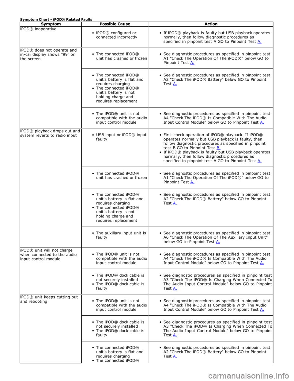
Symptom Chart - iPOD® Related Faults
Symptom Possible Cause Action iPOD® inoperative
iPOD® configured or
connected incorrectly
If iPOD® playback is faulty but USB playback operates
normally, then follow diagnostic procedures as
specified in pinpoint test A GO to Pinpoint Test A. iPOD® does not operate and
in-car display shows "99" on
the screen
The connected iPOD®
unit has crashed or frozen
See diagnostic procedures as specified in pinpoint test
A1 "Check The Operation Of The iPOD®" below GO to
Pinpoint Test A.
The connected iPOD®
unit's battery is flat and
requires charging
The connected iPOD®
unit's battery is not
holding charge and
requires replacement
See diagnostic procedures as specified in pinpoint test
A2 "Check The iPOD® Battery" below GO to Pinpoint
Test A.
The iPOD® unit is not
compatible with the audio
input control module
See diagnostic procedures as specified in pinpoint test
A4 "Check The iPOD® Is Compatible With The Audio
Input Control Module" below GO to Pinpoint Test A. iPOD® playback drops out and
system reverts to radio input
USB input or iPOD® input
faulty
First check operation of iPOD® playback. If iPOD®
operates normally but USB playback is faulty, then
follow diagnostic procedures as specified in pinpoint
test B GO to Pinpoint Test B. If iPOD® playback is faulty but USB playback operates
normally, then follow diagnostic procedures as
specified in pinpoint test A GO to Pinpoint Test A.
The connected iPOD®
unit has crashed or frozen
See diagnostic procedures as specified in pinpoint test
A1 "Check The Operation Of The iPOD®" below GO to
Pinpoint Test A.
The connected iPOD®
unit's battery is flat and
requires charging
The connected iPOD®
unit's battery is not
holding charge and
requires replacement
See diagnostic procedures as specified in pinpoint test
A2 "Check The iPOD® Battery" below GO to Pinpoint
Test A.
The auxiliary input unit is
faulty
See diagnostic procedures as specified in pinpoint test
A6 "Check The Operation Of The Auxiliary Input Unit"
below GO to Pinpoint Test A. iPOD® unit will not charge
when connected to the audio
input control module
The iPOD® unit is not
compatible with the audio
input control module
See diagnostic procedures as specified in pinpoint test
A4 "Check The iPOD® Is Compatible With The Audio
Input Control Module" below GO to Pinpoint Test A.
The iPOD® dock cable is
not securely installed
The iPOD® dock cable is
faulty
See diagnostic procedures as specified in pinpoint test
A3 "Check The iPOD® Is Charging When Connected To
The Audio Input Control Module" below GO to Pinpoint
Test A. iPOD® unit keeps cutting out
and rebooting
The iPOD® unit is not
compatible with the audio
input control module
See diagnostic procedures as specified in pinpoint test
A4 "Check The iPOD® Is Compatible With The Audio
Input Control Module" below GO to Pinpoint Test A.
The iPOD® dock cable is
not securely installed
The iPOD® dock cable is
faulty
See diagnostic procedures as specified in pinpoint test
A3 "Check The iPOD® Is Charging When Connected To
The Audio Input Control Module" below GO to Pinpoint
Test A.
The connected iPOD®
unit's battery is flat and
requires charging
The connected iPOD®
See diagnostic procedures as specified in pinpoint test
A2 "Check The iPOD® Battery" below GO to Pinpoint
Test A.
Page 2064 of 3039

DTC Description Possible Cause Action B116515
Left Front
Puddle Lamp
Output
Left front puddle lamp
control circuit - short to
power, open circuit Carry out any pinpoint tests associated with this DTC using the
manufacturer approved diagnostic system. Refer to the electrical
circuit diagrams and test left front puddle lamp control circuit
for short to power, open circuit B116611
Right Front
Puddle Lamp
Output
Right front puddle lamp
control circuit - short to
ground Refer to the electrical circuit diagrams and test right front
puddle lamp control circuit for short to ground B116615
Right Front
Puddle Lamp
Output
Right front puddle lamp
control circuit - short to
power, open circuit Carry out any pinpoint tests associated with this DTC using the
manufacturer approved diagnostic system. Refer to the electrical
circuit diagrams and test right front puddle lamp control circuit
for short to power, open circuit B111E11
Boot/Trunk
Lamps
Luggage compartment lamp
control circuit - short to
ground Carry out any pinpoint test associated with this DTC using the
manufacturer approved diagnostic system. Refer to the electrical
circuit diagrams and check luggage compartment lamp control
circuit for short to ground B111E15
Boot/Trunk
Lamps
Luggage compartment lamp
control circuit - short to
power, open circuit Carry out any pinpoint test associated with this DTC using the
manufacturer approved diagnostic system. Refer to the electrical
circuit diagrams and check luggage compartment lamp control
circuit for short to power, open circuit B112412
Lamp Fade
Control
Interior lamp fade control
circuit - short to power Refer to the electrical circuit diagrams and check interior lamp
fade control circuit for short to power B113C12
Hazard Switch
Illumination
Hazard switch illumination
control circuit - short to
power Refer to the electrical circuit diagrams and check hazard switch
illumination control circuit for short to power B1A8596
Ambient Light
Sensor
Light sensor internal
electronic failure Check and install a new sensor as required U201012
Switch
Illumination
Switch/interior illumination
PWM supply circuit - short to
power Refer to the electrical circuit diagrams and check switch/interior
illumination PWM supply circuit for short to power U201014
Switch
Illumination
Switch/interior illumination
PWM supply circuit - short to
ground, open circuit Refer to the electrical circuit diagrams and check switch/interior
illumination PWM supply circuit for short to ground, open circuit