differential JAGUAR XFR 2010 1.G User Guide
[x] Cancel search | Manufacturer: JAGUAR, Model Year: 2010, Model line: XFR, Model: JAGUAR XFR 2010 1.GPages: 3039, PDF Size: 58.49 MB
Page 483 of 3039
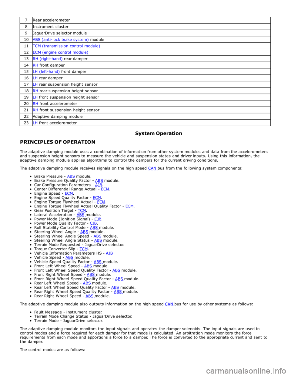
7 Rear accelerometer 8 Instrument cluster 9 JaguarDrive selector module 10 ABS (anti-lock brake system) module 11 TCM (transmission control module) 12 ECM (engine control module) 13 RH (right-hand) rear damper 14 RH front damper 15 LH (left-hand) front damper 16 LH rear damper 17 LH rear suspension height sensor 18 RH rear suspension height sensor 19 LH front suspension height sensor 20 RH front accelerometer 21 RH front suspension height sensor 22 Adaptive damping module 23 LH front accelerometer
PRINCIPLES OF OPERATION System Operation
The adaptive damping module uses a combination of information from other system modules and data from the accelerometers
and suspension height sensors to measure the vehicle and suspension states and driver inputs. Using this information, the
adaptive damping module applies algorithms to control the dampers for the current driving conditions.
The adaptive damping module receives signals on the high speed CAN bus from the following system components: Brake Pressure - ABS module. Brake Pressure Quality Factor - ABS module. Car Configuration Parameters - AJB. Center Differential Range Actual - ECM. Engine Speed - ECM. Engine Speed Quality Factor - ECM. Engine Torque Flywheel Actual - ECM. Engine Torque Flywheel Actual Quality Factor - ECM. Gear Position Target - TCM. Lateral Acceleration - ABS module. Power Mode (Ignition Signal) - CJB. Power Mode Quality Factor - CJB. Roll Stability Control Mode - ABS module. Steering Wheel Angle - ABS module. Steering Wheel Angle Speed - ABS module. Steering Wheel Angle Status - ABS module. Terrain Mode Requested - JaguarDrive selector.
Torque Converter Slip - TCM. Vehicle Information Parameters HS - AJB Vehicle Speed - ABS module. Vehicle Speed Quality Factor - ABS module. Front Left Wheel Speed - ABS module. Front Left Wheel Speed Quality Factor - ABS module. Front Right Wheel Speed - ABS module. Front Right Wheel Speed Quality Factor - ABS module. Rear Left Wheel Speed - ABS module. Rear Left Wheel Speed Quality Factor - ABS module. Rear Right Wheel Speed Quality Factor - ABS module. Rear Right Wheel Speed - ABS module. The adaptive damping module also outputs information on the high speed CAN bus for use by other systems as follows: Fault Message - instrument cluster.
Terrain Mode Change Status - JaguarDrive selector.
Terrain Mode - JaguarDrive selector.
The adaptive damping module monitors the input signals and operates the damper solenoids. The input signals are used in
control modes and a force required for each damper for that mode is calculated. An arbitration mode monitors the force
requirements from each mode and apportions a force to a damper. The force is converted to the appropriate current and sent to
the damper.
The control modes are as follows:
Page 499 of 3039
Driveline System - General Information - Driveline System
Diagnosis and Testing
Principle of Operation Published: 11-May-2011
For a detailed description of driveline operation, refer to the relevant Description and Operation section in the workshop
manual. REFER to:
Driveshaft (205-01 Driveshaft, Description and Operation), Driveshaft (205-01 Driveshaft, Description and Operation), Driveshaft (205-01 Driveshaft, Description and Operation), Rear Drive Axle and Differential (205-02, Description and Operation),
Rear Drive Axle and Differential (205-02, Description and Operation),
Rear Drive Axle and Differential (205-02, Description and Operation),
Rear Drive Halfshafts (205-05 Rear Drive Halfshafts, Description and Operation), Rear Drive Halfshafts (205-05 Rear Drive Halfshafts, Description and Operation), Rear Drive Halfshafts (205-05 Rear Drive Halfshafts, Description and Operation).
Inspection and Verification
CAUTION: Only serviceable items can be renewed or adjusted. Failure to follow this instruction may result in the warranty
of the component being rejected.
Certain driveline trouble symptoms are also common to the engine, transmission, wheel bearings, tires, and other parts of the
vehicle. For this reason, make sure that the cause of the trouble is in the driveline before adjusting, repairing, or installing any
new components. For additional information, refer to Workshop Manual section 100-04 Noise, Vibration and Harshness.
1. Verify the customer concern by carrying out a road test of the vehicle.
2. Visually inspect for obvious signs of mechanical damage and system integrity.
3. If an obvious cause for an observed or reported concern is found, correct the cause (if possible) before proceeding to
the next step.
4. If the concern is not visually evident, verify the symptom and refer to the Symptom Chart.
Identify the Condition
Gear Howl and Whine
Howling or whining of the ring gear and pinion is due to an incorrect gear pattern, gear damage or incorrect bearing preload.
Bearing Whine
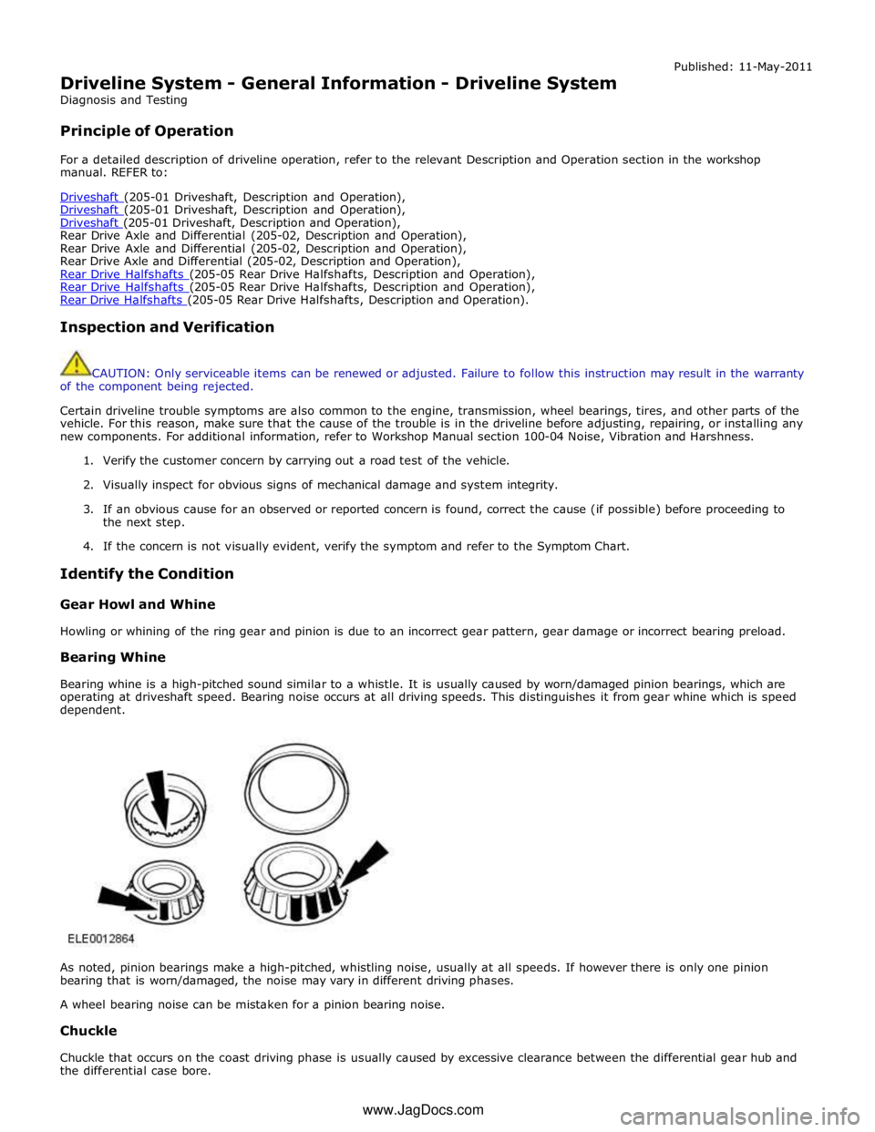
Bearing whine is a high-pitched sound similar to a whistle. It is usually caused by worn/damaged pinion bearings, which are
operating at driveshaft speed. Bearing noise occurs at all driving speeds. This distinguishes it from gear whine which is speed
dependent.
As noted, pinion bearings make a high-pitched, whistling noise, usually at all speeds. If however there is only one pinion
bearing that is worn/damaged, the noise may vary in different driving phases.
A wheel bearing noise can be mistaken for a pinion bearing noise.
Chuckle
Chuckle that occurs on the coast driving phase is usually caused by excessive clearance between the differential gear hub and
the differential case bore. www.JagDocs.com
Page 502 of 3039
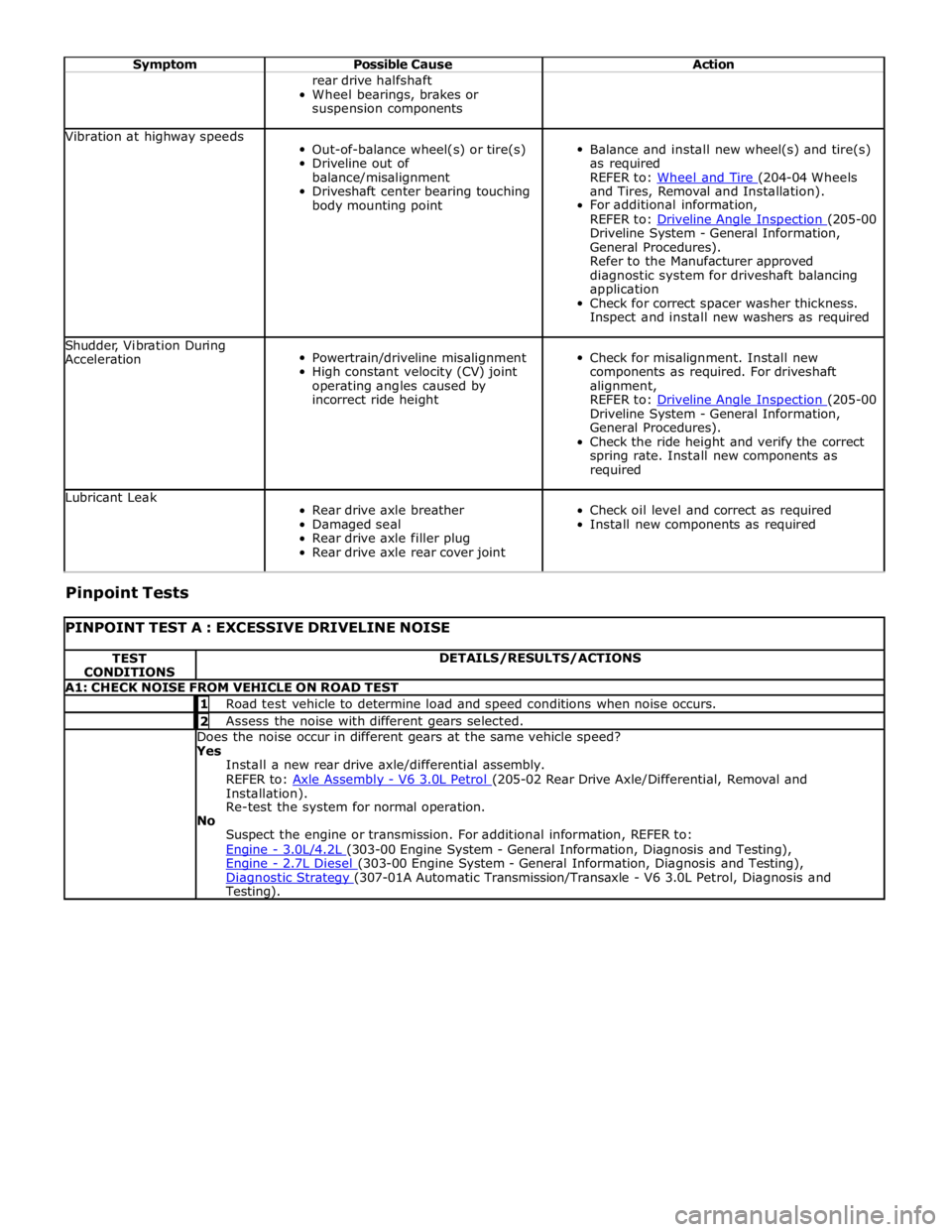
Symptom Possible Cause Action rear drive halfshaft
Wheel bearings, brakes or
suspension components Vibration at highway speeds
Out-of-balance wheel(s) or tire(s)
Driveline out of
balance/misalignment
Driveshaft center bearing touching
body mounting point
Balance and install new wheel(s) and tire(s)
as required
REFER to: Wheel and Tire (204-04 Wheels and Tires, Removal and Installation).
For additional information,
REFER to: Driveline Angle Inspection (205-00 Driveline System - General Information,
General Procedures).
Refer to the Manufacturer approved
diagnostic system for driveshaft balancing
application
Check for correct spacer washer thickness.
Inspect and install new washers as required Shudder, Vibration During
Acceleration
Powertrain/driveline misalignment
High constant velocity (CV) joint
operating angles caused by
incorrect ride height
Check for misalignment. Install new
components as required. For driveshaft
alignment,
REFER to: Driveline Angle Inspection (205-00 Driveline System - General Information,
General Procedures).
Check the ride height and verify the correct
spring rate. Install new components as
required Lubricant Leak
Rear drive axle breather
Damaged seal
Rear drive axle filler plug
Rear drive axle rear cover joint
Check oil level and correct as required
Install new components as required Pinpoint Tests
PINPOINT TEST A : EXCESSIVE DRIVELINE NOISE TEST
CONDITIONS DETAILS/RESULTS/ACTIONS A1: CHECK NOISE FROM VEHICLE ON ROAD TEST 1 Road test vehicle to determine load and speed conditions when noise occurs. 2 Assess the noise with different gears selected. Does the noise occur in different gears at the same vehicle speed? Yes
Install a new rear drive axle/differential assembly.
REFER to: Axle Assembly - V6 3.0L Petrol (205-02 Rear Drive Axle/Differential, Removal and Installation).
Re-test the system for normal operation.
No
Suspect the engine or transmission. For additional information, REFER to:
Engine - 3.0L/4.2L (303-00 Engine System - General Information, Diagnosis and Testing), Engine - 2.7L Diesel (303-00 Engine System - General Information, Diagnosis and Testing), Diagnostic Strategy (307-01A Automatic Transmission/Transaxle - V6 3.0L Petrol, Diagnosis and Testing).
Page 512 of 3039
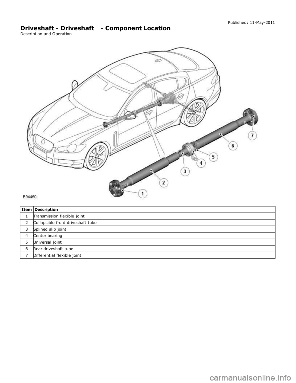
1 Transmission flexible joint 2 Collapsible front driveshaft tube 3 Splined slip joint 4 Center bearing 5 Universal joint 6 Rear driveshaft tube 7 Differential flexible joint
Page 513 of 3039

Driveshaft - Driveshaft - Overview
Description and Operation
Driveshaft Overview Published: 11-May-2011
The two-piece driveshaft, manufactured from lightweight tubular steel, transmits drive from the engine, via the transmission,
to the differential. The driveshaft aligns with the centerline of the vehicle’s body and is supported by a center bearing.
Page 514 of 3039

Published: 11-May-2011
Driveshaft - Driveshaft - System Operation and Component Description
Description and Operation
Driveshaft System Operation
The two-piece driveshaft, manufactured from lightweight tubular steel, transmits drive from the engine, via the transmission,
to the differential. The driveshaft aligns with the centerline of the vehicle’s body and is supported by a center bearing.
The driveshaft's front tube is of swaged construction, which is a crash energy management feature, designed to collapse
progressively and predictably in the event of a severe frontal impact. A low-friction splined slip-joint at the center of the
driveshaft provide the driveshaft's plunge capability.
Flexible couplings connecting the driveshaft to both the transmission and the differential counteract the angular movement of
the driveshaft caused by the driveline's acceleration and braking forces.
The center universal joint is positioned at a specified angle using shims between the center bearing and the vehicle's body.
The driveline angles have been carefully configured to balance minimum power losses with excellent vibration and wear
characteristics. The universal joint is lubricated during manufacture and sealed for life.
www.JagDocs.com
Page 515 of 3039
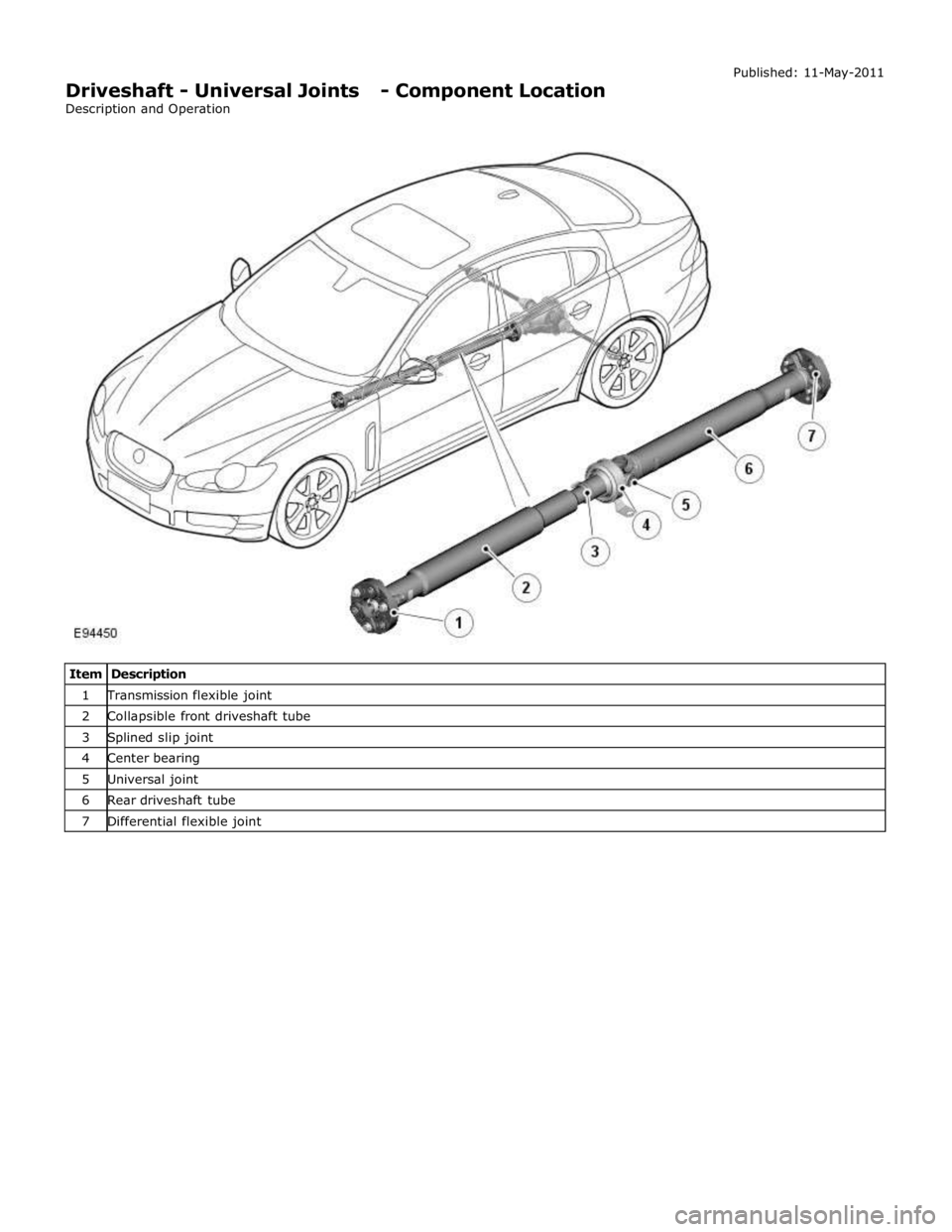
1 Transmission flexible joint 2 Collapsible front driveshaft tube 3 Splined slip joint 4 Center bearing 5 Universal joint 6 Rear driveshaft tube 7 Differential flexible joint
Page 522 of 3039
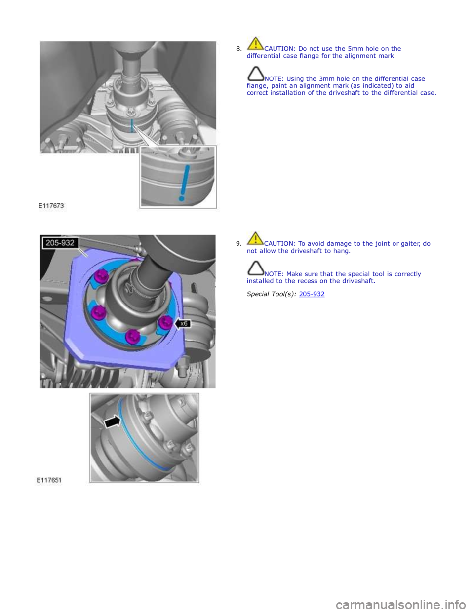
8. CAUTION: Do not use the 5mm hole on the
differential case flange for the alignment mark.
NOTE: Using the 3mm hole on the differential case
flange, paint an alignment mark (as indicated) to aid
correct installation of the driveshaft to the differential case.
9. CAUTION: To avoid damage to the joint or gaiter, do
not allow the driveshaft to hang.
NOTE: Make sure that the special tool is correctly
installed to the recess on the driveshaft.
Special Tool(s): 205-932
Page 524 of 3039
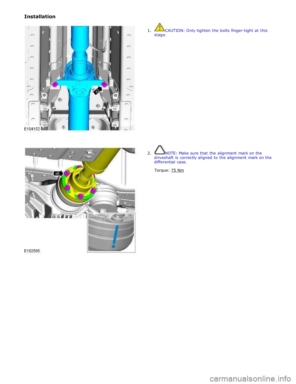
Installation
1. CAUTION: Only tighten the bolts finger-tight at this
stage.
2. NOTE: Make sure that the alignment mark on the
driveshaft is correctly aligned to the alignment mark on the
differential case.
Torque: 75 Nm
Page 525 of 3039
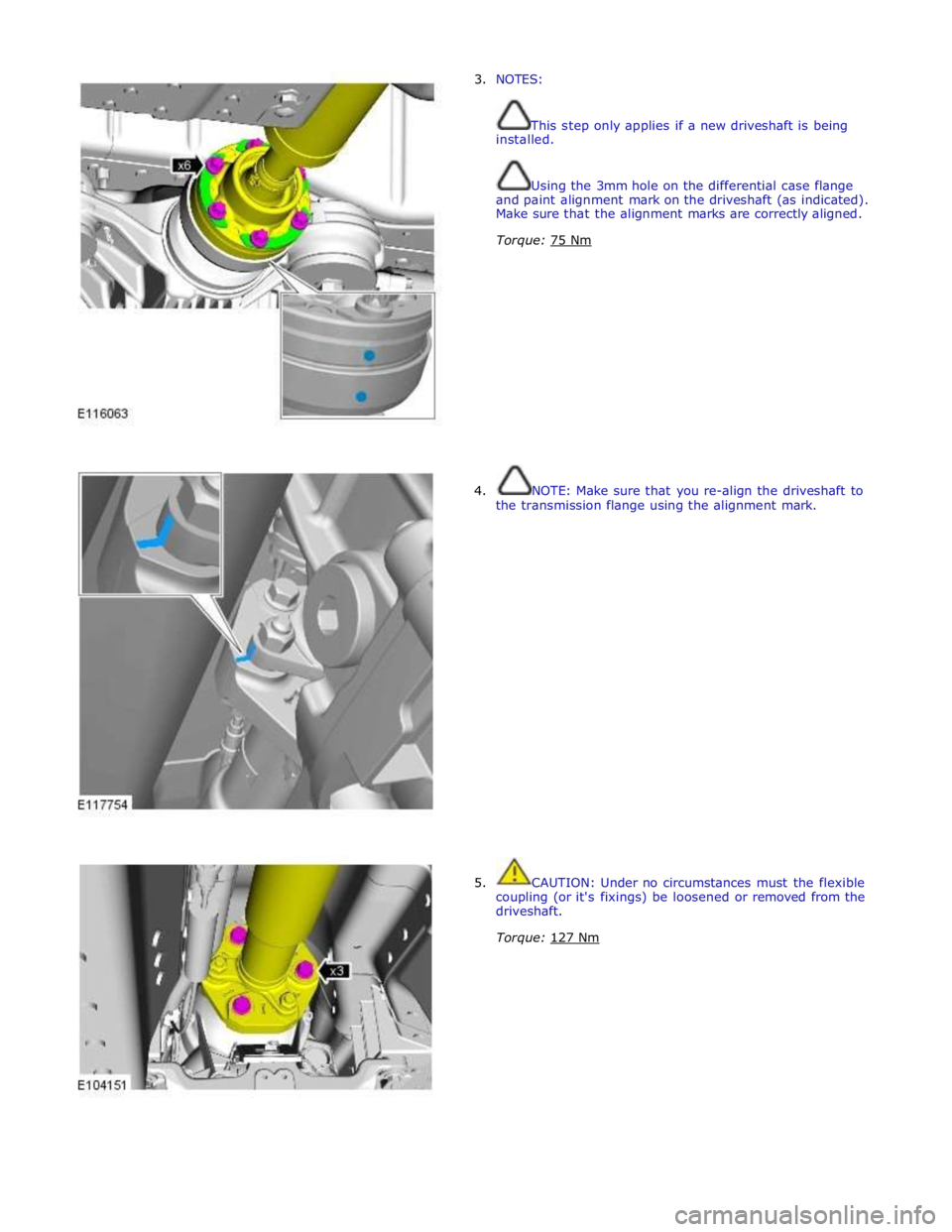
3. NOTES:
This step only applies if a new driveshaft is being
installed.
Using the 3mm hole on the differential case flange
and paint alignment mark on the driveshaft (as indicated).
Make sure that the alignment marks are correctly aligned.
Torque: 75 Nm
4. NOTE: Make sure that you re-align the driveshaft to
the transmission flange using the alignment mark.
5. CAUTION: Under no circumstances must the flexible
coupling (or it's fixings) be loosened or removed from the
driveshaft.
Torque: 127 Nm