wheel JAGUAR XFR 2010 1.G Workshop Manual
[x] Cancel search | Manufacturer: JAGUAR, Model Year: 2010, Model line: XFR, Model: JAGUAR XFR 2010 1.GPages: 3039, PDF Size: 58.49 MB
Page 4 of 3039

Four-Wheel Alignment
Front Toe Adjustment (57.65.01)
Rear Toe Adjustment (57.65.08)
Front Wheel Bearing and Wheel Hub Runout Check
Rear Wheel Bearing and Wheel Hub Runout Check204-01: Front SuspensionSpecificationDescription and OperationComponent Location
Overview
System Operation and Component DescriptionDiagnosis and TestingFront SuspensionRemoval and InstallationFront Shock Absorber (60.30.04)
Front Lower Arm (60.35.53)
Rear Lower Arm (60.35.54)
Rear Lower Arm Bushing (60.40.12)
Shock Absorber Bushing (60.30.16) (60.30.23)
Front Stabilizer Bar - V8 5.0L Petrol/V8 S/C 5.0L Petrol
Front Stabilizer Bar Link (60.10.02)
Stabilizer Bar Link Bushing (60.10.03)
Upper Arm LH (60.35.41)
Upper Arm RH (60.35.42)
Front Wheel Bearing and Wheel Hub - TDV6 3.0L Diesel /V8 5.0L Petrol/V8 S/C 5.0L Petrol
Wheel Knuckle (60.25.23)
Front Lower Arm Bushing204-02: Rear SuspensionSpecificationDescription and OperationComponent Location
Overview
System Operation and Component DescriptionDiagnosis and TestingRear SuspensionRemoval and InstallationLower Arm (64.35.43)
Shock Absorber and Spring Assembly
Shock Absorber Lower Bushing (64.30.39)
Rear Stabilizer Bar (64.35.08)
Rear Wheel Bearing
Upper Arm
Page 5 of 3039

Disassembly and AssemblyShock Absorber and Spring Assembly204-04: Wheels and TiresSpecificationDescription and OperationComponent Location
Overview
System Operation and Component DescriptionDiagnosis and TestingWheels and TiresRemoval and InstallationTire Low Pressure Sensor
Tire Pressure Monitoring System (TPMS) Front Antenna
Tire Pressure Monitoring System (TPMS) Rear Antenna
Tire Pressure Monitoring System (TPMS) Module
Tire Pressure Monitoring System (TPMS) Receiver
Wheel and Tire204-05: Vehicle Dynamic Suspension
Description and OperationComponent Location - V8 5.0L Petrol/V8 S/C 5.0L Petrol
Overview - V8 5.0L Petrol/V8 S/C 5.0L Petrol
System Operation and Component Description - V8 5.0L Petrol/V8 S/C 5.0L PetrolDiagnosis and TestingVehicle Dynamic SuspensionRemoval and InstallationAdaptive Damping Module
Front Suspension Vertical Accelerometer
Rear Suspension Vertical Accelerometer204-06: Ride and Handling Optimization
Description and OperationComponent Location
Overview
System Operation and Component Description205: Driveline
205-00: Driveline System - General Information
Diagnosis and TestingDriveline SystemGeneral ProceduresDriveline Angle Inspection205-01: DriveshaftSpecification
Page 7 of 3039

Diagnosis and TestingBrake SystemGeneral ProceduresBrake Disc Runout Check
Brake System Bleeding (70.25.03)
Front Brake Disc Runout Check - With Wheel On - Vehicles With: High Performance Brakes
Rear Brake Disc Runout Check - With Wheel On206-03B: Front Disc Brake - TDV6 3.0L Diesel /V8 5.0L Petrol/V8 S/C 5.0L PetrolSpecificationDescription and OperationComponent Location
Overview
System Operation and Component DescriptionRemoval and InstallationBrake Caliper - Vehicles With: High Performance Brakes
Brake Disc - Vehicles With: High Performance Brakes
Brake Pads - Vehicles With: High Performance Brakes
Brake Disc Shield (70.10.18) - Vehicles With: High Performance Brakes206-04B: Rear Disc Brake - TDV6 3.0L Diesel /V8 5.0L Petrol/V8 S/C 5.0L PetrolSpecificationDescription and OperationComponent Location
Overview
System Operation and Component DescriptionRemoval and InstallationBrake Caliper - Vehicles With: High Performance Brakes
Brake Disc - Vehicles With: High Performance Brakes
Brake Pads - Vehicles With: High Performance Brakes
Brake Disc Shield (70.10.19)206-05: Parking Brake and ActuationSpecificationDescription and OperationComponent Location
Overview
System Operation and Component DescriptionDiagnosis and TestingParking BrakeGeneral ProceduresParking Brake Cable Tension ReleaseRemoval and InstallationParking Brake Cable LH - TDV6 3.0L Diesel /V8 5.0L Petrol/V8 S/C 5.0L Petrol
Parking Brake Cable RH - TDV6 3.0L Diesel /V8 5.0L Petrol/V8 S/C 5.0L Petrol
Page 8 of 3039

Parking Brake Module
Parking Brake Switch
Parking Brake Release Actuator206-06: Hydraulic Brake ActuationSpecificationDescription and OperationComponent Location
Overview
System Operation and Component DescriptionDiagnosis and TestingHydraulic Brake ActuationRemoval and InstallationBrake Fluid Reservoir (70.30.16)
Brake Master Cylinder (70.30.08)206-07: Power Brake ActuationSpecificationDescription and OperationComponent Location
OverviewDiagnosis and TestingPower Brake SystemRemoval and InstallationBrake Booster (70.50.17)
Brake Vacuum Pump - V8 5.0L Petrol/V8 S/C 5.0L Petrol206-09: Anti-Lock Control - Stability AssistSpecificationDescription and OperationComponent Location
Overview
System Operation and Component DescriptionDiagnosis and TestingAnti-Lock Control - Stability AssistRemoval and InstallationAnti-Lock Brake System (ABS) Module (70.60.02)
Front Wheel Speed Sensor
Hydraulic Control Unit (HCU) (70.60.18) (70.60.19)
Rear Wheel Speed Sensor (70.60.04)
Steering Wheel Rotation Sensor
Yaw Rate Sensor and Accelerometer211: Steering System
211-00: Steering System - General InformationSpecification
Page 9 of 3039

Diagnosis and TestingSteering SystemGeneral ProceduresPower Steering System Bleeding (57.15.02 )
Power Steering System Flushing (57.15.08)
Power Steering System Filling - V8 5.0L Petrol/V8 S/C 5.0L Petrol211-02: Power SteeringSpecificationDescription and OperationComponent Location
Overview
System Operation and Component DescriptionDiagnosis and TestingPower SteeringRemoval and InstallationSteering Gear (57.10.01)
Power Steering Fluid Reservoir - V8 5.0L Petrol/V8 S/C 5.0L Petrol
Power Steering Pump - V8 5.0L Petrol/V8 S/C 5.0L Petrol
Power Steering Pump to Steering Gear Pressure Line - V8 5.0L Petrol/V8 S/C 5.0L Petrol
Steering Gear to Fluid Cooler Return Hose - V8 5.0L Petrol/V8 S/C 5.0L Petrol211-03: Steering LinkageSpecificationDescription and OperationComponent Location
Overview
System Operation and Component DescriptionDiagnosis and TestingSteering LinkageRemoval and InstallationTie Rod End (57.55.02)211-04: Steering ColumnSpecificationDescription and OperationComponent Location
Overview
System Operation and Component DescriptionDiagnosis and TestingSteering ColumnRemoval and InstallationSteering Column
Steering Column Flexible Coupling
Steering Wheel (57.60.01)
Page 22 of 3039

Operation and
Component DescriptionCellular PhoneComponent
Location
Overview
System Operation
and Component DescriptionNavigation SystemComponent Location
Overview
System Operation and Component DescriptionVideo SystemComponent
Location
Overview
System Operation
and Component DescriptionDiagnosis and TestingInformation and Entertainment SystemRemoval and InstallationAudio Unit
Audio Unit Antenna Amplifier
Audio and Climate Control Assembly
Front Door Speaker
Information and Entertainment Display
Information and Entertainment Module
Instrument Panel Speaker
Rear Door Speaker
Steering Wheel Audio Controls
Subwoofer Amplifier
Subwoofer Speaker
Satellite Radio Tuner415-01B: Information and Entertainment System - DTC: Audio Input Control Module
Diagnosis and TestingAudio Input Control Module417: Lighting
417-01: Exterior LightingSpecificationDescription and OperationComponent Location
Overview
System Operation and Component DescriptionDiagnosis and TestingHeadlampsGeneral ProceduresHeadlamp Adjustment (86.40.18)
Page 31 of 3039

Removal and InstallationFender Apron Closing Panel Front Section
Fender Apron Panel
Fender Apron Panel Closing Panel
Fender Apron Panel Front Extension
Fender Apron Panel Front Section
Front Bumper Mounting
Front Fender
Front Fender Support Bracket
Front Side Member
Front Side Member and Suspension Top Mount Assembly
Front Side Member Closing Panel
Front Side Member Closing Panel Section
Front Side Member Section
Front Wheelhouse Section
Hood Latch Panel
Hood Latch Panel Mounting Bracket501-28: Roof Sheet Metal Repairs
Description and OperationRoofRemoval and InstallationRoof Panel - Vehicles With: Sliding Roof Opening Panel
Roof Panel - Vehicles Without: Sliding Roof Opening Panel501-29: Side Panel Sheet Metal Repairs
Description and OperationSide Panel Sheet MetalRemoval and InstallationA-Pillar Outer Panel
A-Pillar Reinforcement
B-Pillar Inner Panel
B-Pillar Reinforcement
Front Door Skin Panel
Rear Door Skin Panel
Rocker Panel
Rocker Panel and B-Pillar Outer Panel
Rocker Panel Front Section
Rocker Panel Inner Reinforcement
Rocker Panel Rear Section501-30: Rear End Sheet Metal Repairs
Description and OperationRear End Sheet Metal
Page 32 of 3039

Removal and InstallationBack Panel
Quarter Panel
Quarter Panel Lower Extension
Rear Bumper Mounting
Rear Floor Side Extension
Rear Side Member Closing Panel Section
Rear Side Member Section
Rear Wheelhouse Outer
Spare Wheel Well502: Frame and Mounting
502-00: Uni-Body, Subframe and Mounting SystemSpecificationRemoval and InstallationFront Subframe - V8 5.0L Petrol/V8 S/C 5.0L Petrol
Rear Subframe - V8 5.0L Petrol/V8 S/C 5.0L Petrol
Rear Subframe Rear Bushing (64.25.36) - TDV6 3.0L Diesel /V8 5.0L Petrol/V8 S/C 5.0L Petrol
Page 33 of 3039

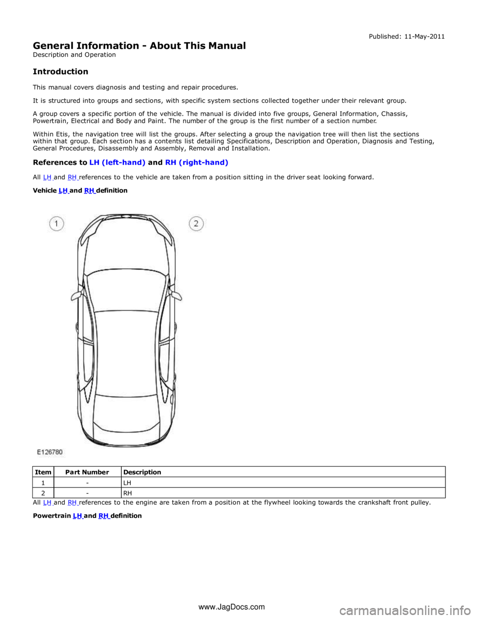
Vehicle LH and RH definition
Item Part Number Description 1 - LH 2 - RH All LH and RH references to the engine are taken from a position at the flywheel looking towards the crankshaft front pulley.
Powertrain LH and RH definition
www.JagDocs.com
Page 49 of 3039

General Information - General Service Information
Description and Operation
Repairs and Replacements Published: 28-Dec-2012
When service parts are required, it is essential that only genuine Jaguar/Daimler replacements are used.
Attention is drawn to the following points concerning repairs and the installation of replacement parts and accessories:
Safety features embodied in the vehicle may be impaired if other than genuine parts are installed. In certain territories,
legislation prohibits the installation of parts which are not produced to the vehicle manufacturer's specification.
Torque wrench setting figures given in this manual must be strictly adhered to. Locking devices, where specified, must
be installed. If the efficiency of a locking device is impaired during removal it must be renewed.
Owners purchasing accessories while travelling abroad should make sure that the accessory and its installed location on
the vehicle conform to mandatory requirements existing in their country of origin.
The vehicle warranty may be invalidated by the installation of other than genuine Jaguar/Daimler parts. All
Jaguar/Daimler replacements have the full backing of the factory warranty.
Jaguar/Daimler dealers are obliged to supply only genuine service parts.
Vehicle Specifications
Purchasers are advised that the specification details set out in this manual apply to a range of vehicles and not to any specific
one. For the specification of a particular vehicle, purchasers should consult their dealer.
The Manufacturer reserves the right to vary the specifications, with or without notice, and at such times and in such manner as
the Manufacturer thinks fit. Major as well as minor changes may be involved, in accordance with the Manufacturer's policy of
continuous improvement.
Whilst every effort is made to make sure the accuracy of the particulars contained in this manual, neither the Manufacturer nor
the Dealer, by whom the manual is supplied, shall in any circumstances be held liable for any inaccuracy or the consequences
thereof.
Service Repair Operation Numbering
A master index of numbered operations has been compiled for universal application to all vehicles manufactured by Jaguar
Land Rover Limited.
Each operation is allocated a number from the master index and cross-refers with an identical number in the Repair Operation
Times schedule. The number consists of six digits arranged in three pairs.
Each maintenance procedure in this manual is described in the sequence necessary to complete the operation in the minimum
time, as specified in the Repair Operation Times schedule.
References to Bank-1 and Bank-2
References to Bank-1 and Bank-2 are made with regard to the engine. When viewed from the flywheel the right-hand bank will
be Bank-1 and the left-hand bank will be Bank-2.
Special Tools
Any special tools and equipment required to perform a maintenance procedure, are shown at the beginning of each procedure.
When possible, illustrations are given to assist in identifying the tool needed.
Disconnecting/Connecting the Battery
Always stop the engine before disconnecting the battery negative lead and make sure the battery positive lead is isolated i.e.
wrapped in a suitable cloth.
WARNING: Radio code saving devices must not be used when conducting work on Air Bag or Fuel systems. It must be
noted that, when using these devices, the vehicle electrical system is still live albeit with a reduced current flow.
NOTE: Before disconnecting the battery make sure that the radio receiver/cassette player/mini disc player and compact
disc player keycodes are known and, that no data is required from the Engine Control Module (ECM) as battery disconnection
will erase any fault codes and idle/drive values held in the Keep Alive Memory (KAM).
Always disconnect the battery before commencing repair operations which require:
The vehicle to be jacked up
Work on the engine
Work underneath the vehicle
Arc welding
Alternatively a Radio Code Saver may be used, when not working on the Air Bag or Fuel systems. With the battery