Bolt JAGUAR XFR 2010 1.G Workshop Manual
[x] Cancel search | Manufacturer: JAGUAR, Model Year: 2010, Model line: XFR, Model: JAGUAR XFR 2010 1.GPages: 3039, PDF Size: 58.49 MB
Page 2979 of 3039
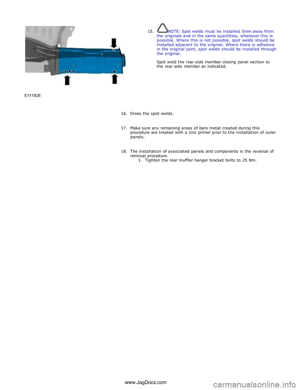
15. NOTE: Spot welds must be installed 5mm away from
the originals and in the same quantities, whenever this is
possible. Where this is not possible, spot welds should be
installed adjacent to the original. Where there is adhesive
in the original joint, spot welds should be installed through
the original.
Spot weld the rear side member closing panel section to
the rear side member as indicated.
16. Dress the spot welds.
17. Make sure any remaining areas of bare metal created during this
procedure are treated with a zinc primer prior to the installation of outer
panels.
18. The installation of associated panels and components is the reversal of
removal procedure.
1. Tighten the rear muffler hanger bracket bolts to 25 Nm. www.JagDocs.com
Page 2982 of 3039

12.
13.
14.
15. NOTE: A new striker reinforcement panel is supplied
on the quarter panel service panel.
Separate the joints, the adhesive and the NVH (noise,
vibration and harshness) component and remove the striker
reinforcement panel.
NOTE: Care should be taken when separating and
removing the ECM (engine control module) mounting
bracket if it is to be reused.
If the right-hand rear wheelhouse outer is to be repaired,
drill out the spot welds as indicated and remove the ECM
mounting bracket. Retain for reuse on installation.
NOTE: It is necessary to section the quarter panel
inner reinforcement at the point indicated, to make sure the
integrity of the safety belt anchorage point. The right-hand
panel is illustrated, the left-hand is similar.
Cut the quarter panel inner reinforcement, horizontally,
approximately 90mm from the centre of the safety belt bolt
anchorage point as indicated.
NOTE: The right-hand panel is illustrated, the
left-hand is similar although there are additional spot welds
to drill out.
Drill out the spot welds from the quarter panel inner
reinforcement section at the points indicated.
Page 3013 of 3039

Front lower arm to front subframe retaining nut and bolt 175 129 - Rear lower arm to front subframe retaining nut and bolt 175 129 - Engine mount lower retaining nut 63 46 - Steering gear retaining bolts 100 74 - Front Shock absorber and spring assembly retaining bolt 175 129 - Front subframe to body front retaining bolt Stage 1 100 73 - Stage 2 270° 270° - Front subframe to body rear retaining bolt Stage 1 80 59 - Stage 2 240° 240° - Front Stabilizer bar link retaining nuts 43 31 - Front Stabilizer bar link retaining bolts 55 41 - Rear Shock absorber and spring assembly retaining bolt 133 98 - Rear subframe reinforcement plate retaining bolts 47 35 - Rear subframe to body retaining bolts Stage 1 80 59 - Stage 2 240° 240° -
Page 3014 of 3039
Published: 31-Jul-2013
Uni-Body, Subframe and Mounting System - Front Subframe V8 5.0L Petrol/V8 S/C 5.0L Petrol
Removal and Installation
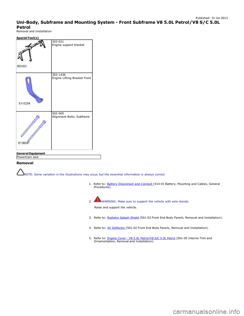
Special Tool(s)
303-021
Engine support bracket
303-1436
Engine Lifting Bracket Front
502-005
Alignment Bolts, Subframe General Equipment
Removal
NOTE: Some variation in the illustrations may occur, but the essential information is always correct.
1. Refer to: Battery Disconnect and Connect (414-01 Battery, Mounting and Cables, General Procedures).
2. WARNING: Make sure to support the vehicle with axle stands.
Raise and support the vehicle.
3. Refer to: Radiator Splash Shield (501-02 Front End Body Panels, Removal and Installation). 4. Refer to: Air Deflector (501-02 Front End Body Panels, Removal and Installation). 5. Refer to: Engine Cover - V8 5.0L Petrol/V8 S/C 5.0L Petrol (501-05 Interior Trim and Ornamentation, Removal and Installation). Powertrain Jack
Page 3020 of 3039
20.
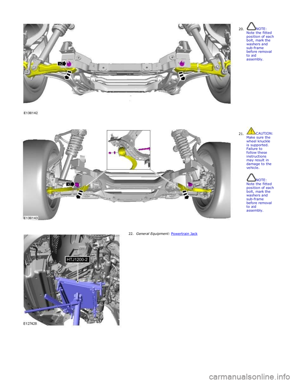
21. NOTE:
Note the fitted position of each bolt, mark the washers and sub-frame before removal to aid assembly.
CAUTION:
Make sure the wheel knuckle is supported. Failure to follow these instructions may result in damage to the vehicle.
NOTE:
Note the fitted position of each bolt, mark the washers and sub-frame before removal to aid assembly.
22. General Equipment: Powertrain Jack
Page 3022 of 3039
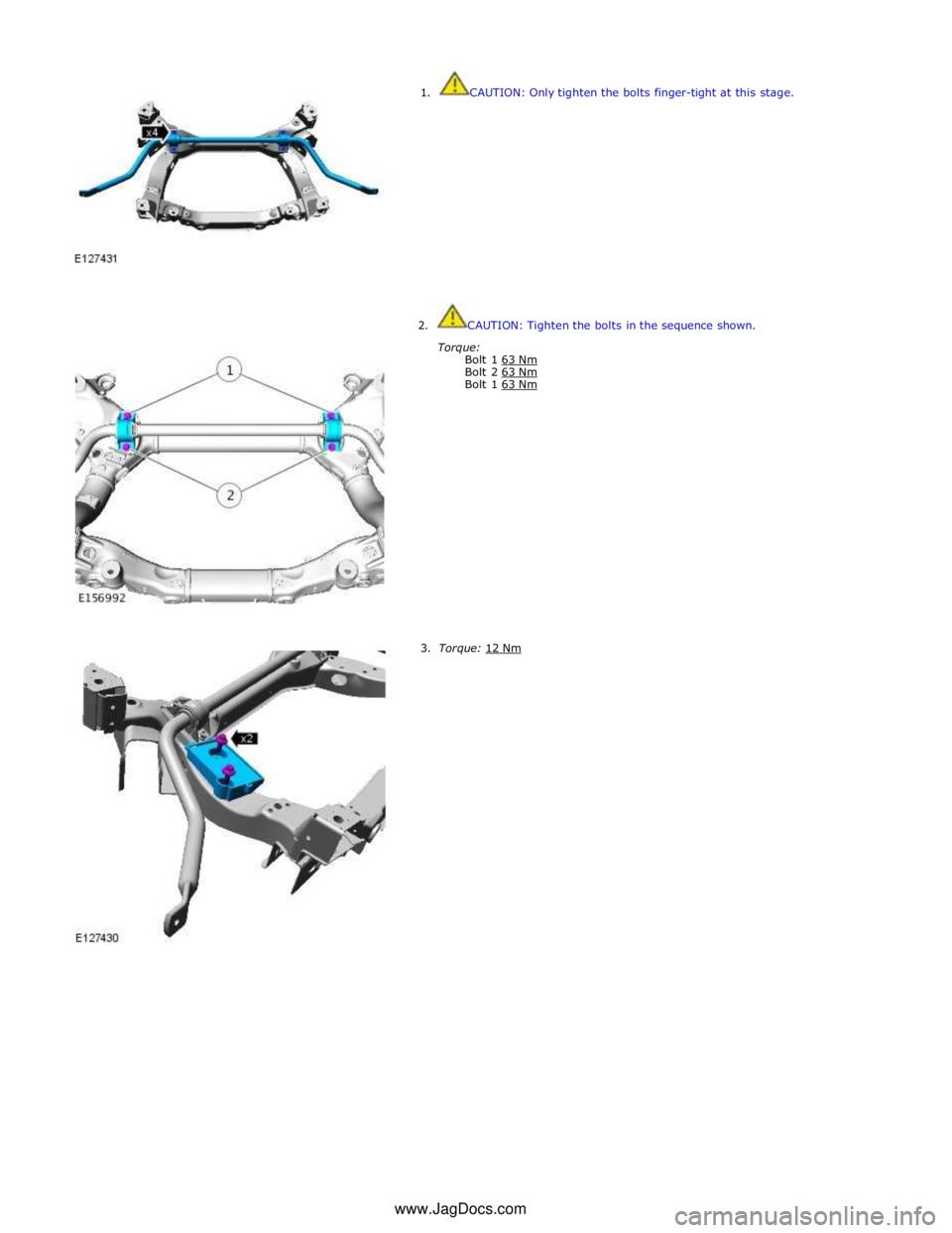
1. CAUTION: Only tighten the bolts finger-tight at this stage.
2. CAUTION: Tighten the bolts in the sequence shown.
Torque:
Bolt 1 63 Nm Bolt 2 63 Nm Bolt 1 63 Nm
3. Torque: 12 Nm www.JagDocs.com
Page 3025 of 3039
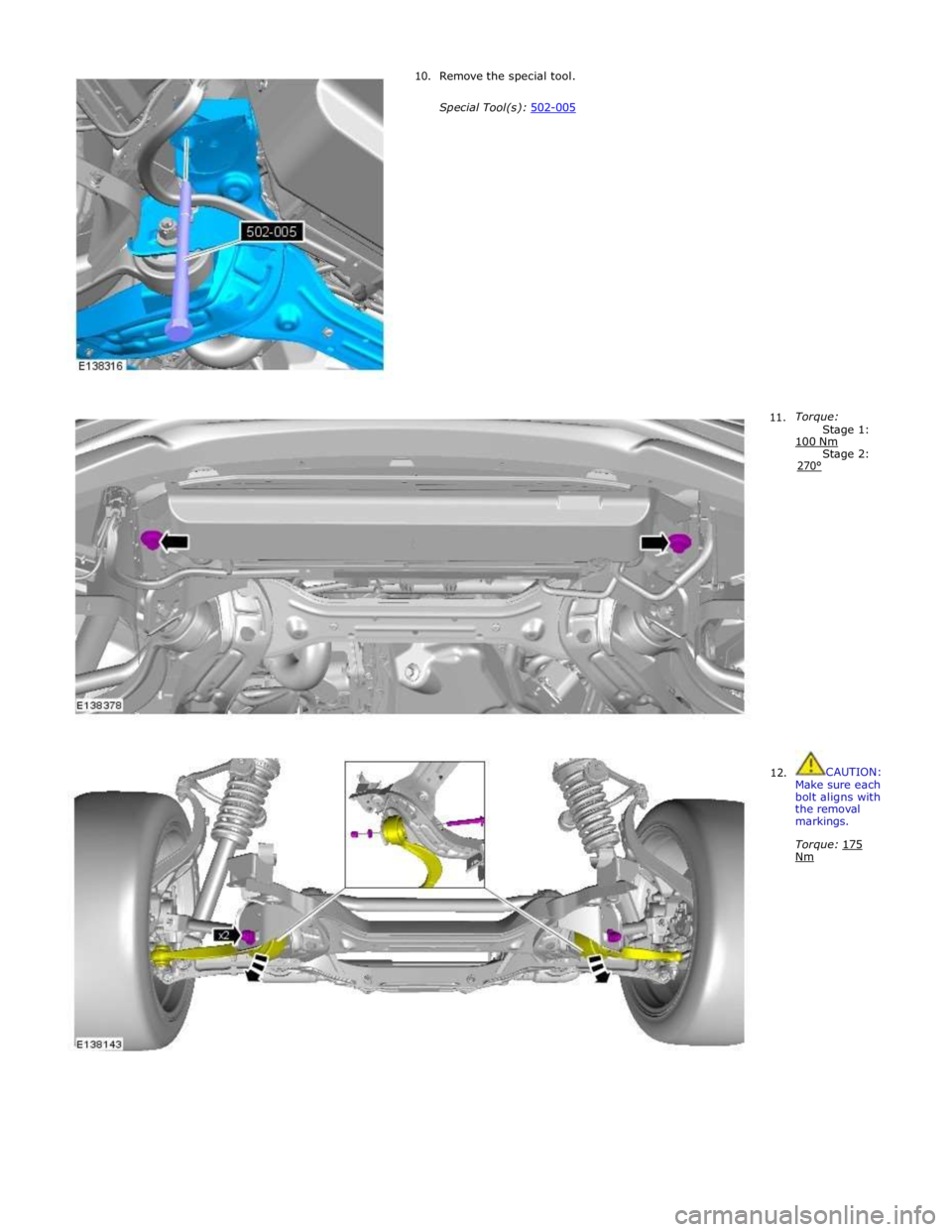
10. Remove the special tool.
Special Tool(s): 502-005
11.
Torque:
Stage 1: 100 Nm Stage 2: 270°
12. CAUTION:
Make sure each bolt aligns with the removal markings.
Torque: 175 Nm
Page 3026 of 3039
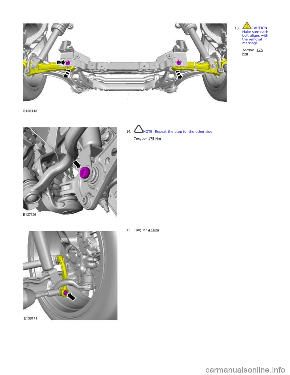
13. CAUTION:
Make sure each bolt aligns with the removal markings.
Torque: 175 Nm
14.
15.
NOTE: Repeat the step for the other side.
Torque: 175 Nm
Torque: 43 Nm
Page 3036 of 3039
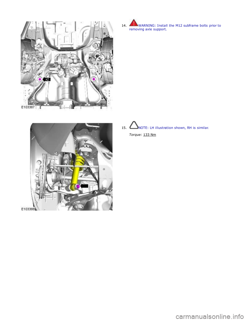
14.
15. WARNING: Install the M12 subframe bolts prior to
removing axle support.
NOTE: LH illustration shown, RH is similar.
Torque: 133 Nm
Page 3037 of 3039
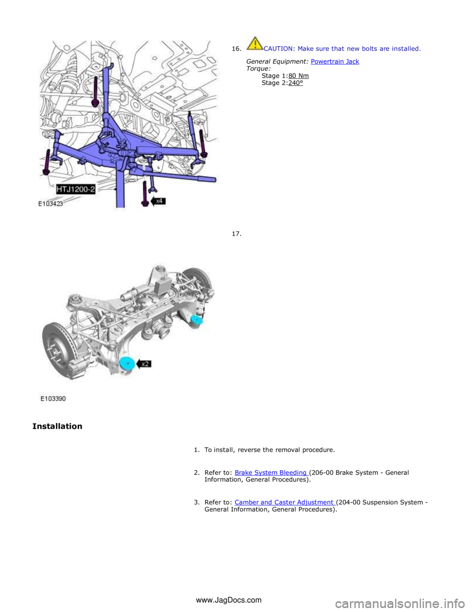
Installation
16.
17.
CAUTION: Make sure that new bolts are installed.
General Equipment: Powertrain Jack Torque:
Stage 1:80 Nm Stage 2:240°
1. To install, reverse the removal procedure.
2. Refer to: Brake System Bleeding (206-00 Brake System - General Information, General Procedures).
3. Refer to: Camber and Caster Adjustment (204-00 Suspension System - General Information, General Procedures). www.JagDocs.com