Bolt JAGUAR XFR 2010 1.G Workshop Manual
[x] Cancel search | Manufacturer: JAGUAR, Model Year: 2010, Model line: XFR, Model: JAGUAR XFR 2010 1.GPages: 3039, PDF Size: 58.49 MB
Page 2213 of 3039
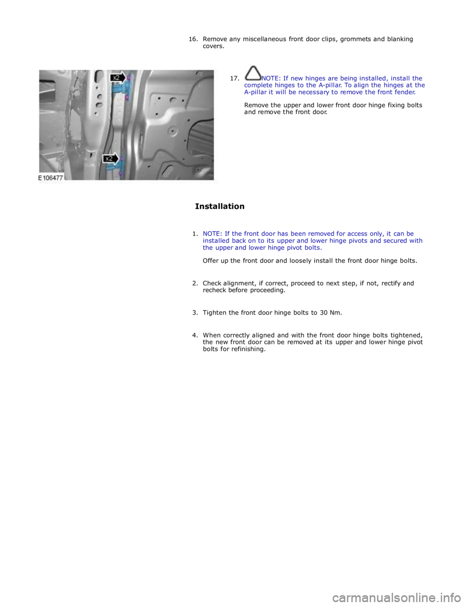
16. Remove any miscellaneous front door clips, grommets and blanking
covers.
17. NOTE: If new hinges are being installed, install the
complete hinges to the A-pillar. To align the hinges at the
A-pillar it will be necessary to remove the front fender.
Remove the upper and lower front door hinge fixing bolts
and remove the front door.
Installation
1. NOTE: If the front door has been removed for access only, it can be
installed back on to its upper and lower hinge pivots and secured with
the upper and lower hinge pivot bolts.
Offer up the front door and loosely install the front door hinge bolts.
2. Check alignment, if correct, proceed to next step, if not, rectify and
recheck before proceeding.
3. Tighten the front door hinge bolts to 30 Nm.
4. When correctly aligned and with the front door hinge bolts tightened,
the new front door can be removed at its upper and lower hinge pivot
bolts for refinishing.
Page 2223 of 3039
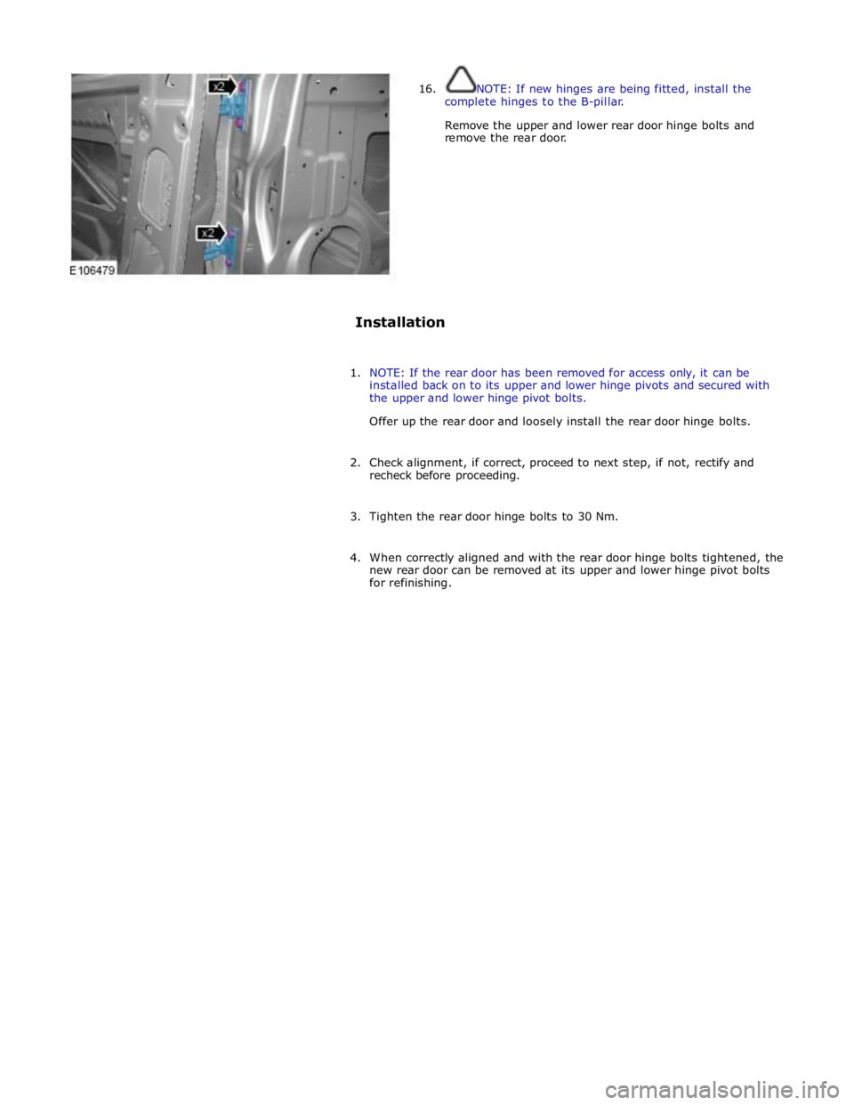
16. NOTE: If new hinges are being fitted, install the
complete hinges to the B-pillar.
Remove the upper and lower rear door hinge bolts and
remove the rear door.
Installation
1. NOTE: If the rear door has been removed for access only, it can be
installed back on to its upper and lower hinge pivots and secured with
the upper and lower hinge pivot bolts.
Offer up the rear door and loosely install the rear door hinge bolts.
2. Check alignment, if correct, proceed to next step, if not, rectify and
recheck before proceeding.
3. Tighten the rear door hinge bolts to 30 Nm.
4. When correctly aligned and with the rear door hinge bolts tightened, the
new rear door can be removed at its upper and lower hinge pivot bolts
for refinishing.
Page 2225 of 3039

Front Safety belt shoulder height adjuster retaining bolt 25 19 - Rear safety belt lower retaining bolt 40 30 - www.JagDocs.com
Page 2307 of 3039

Front seat backrest retaining bolts 35 26 - Front seat safety belt anchor retaining bolts 40 30 - Front seat retaining bolts 47 35 - Front safety belt buckle retaining bolt 40 30 - Rear seat backrest retaining bolts 17 13 - Side air bag module retaining nuts 7 - 62
Page 2317 of 3039

memory positions to be stored and 'set' button with integral LED (light emitting diode). The seat, door mirror and steering
column motors have position sensors which provide feedback to driver's seat module.
Once the driver's seat, steering column and exterior mirrors have been adjusted, the vehicle is able to memorize these
settings for future use by using the following procedure:
Push the memory 'SET' button, the LED in the switch will illuminate Press the memory button 1 or 2 to memorize the current settings. The LED will extinguish, and a chime will sound to confirm that the settings have been memorized. If the ignition is on, power mode 6, the message center will display a
confirmation message.
The positions can be recalled by pressing the applicable button 1 or 2.
Stall Detection
Seat, steering column and mirror motors are deemed to have stalled if there is no change in the inputs that are received from
the corresponding feedback sensors for 200 ms (seat).
If a stall condition is detected then the drive to that motor is cancelled for the remainder of that memory operation (memory
recall) or until the switch is re-selected (manual movement).
If the motor movement has stopped due to loss of sensor feedback, either stall or sensor failure, then that motor may be
activated again, to move past the stall position, by re-selecting the appropriate switch and pressing for longer than 2 seconds.
This allows control of the motor to be maintained if sensor feedback is lost.
Upon re-selection of movement, if sensor pulses are detected then the motor will continue to be driven until the switch is
released or another stall condition is detected. If sensor feedback is not detected then the motor is only driven for 0.5 second
and then stops until the switch is released and then pressed again, when a further 0.5 second of activation is permitted, and
so on, this is known as inch mode.
For all seat motor manual movements, whenever a motor is driven and a stall occurs, the memory control module records the
position at which the stall occurred. If movement occurs beyond a stall position, then that position is erased from the control
modules memory. This will always allow movement past a previously recorded stall position once movement has been
registered beyond that position. This is the case for both manual and memory movement.
Initialization
When a replacement driver's seat module is fitted, it should be calibrated a Jaguar approved diagnostic system so that the
module can learn the seats absolute position.
Battery Monitor
If the battery voltage drops below 10.5 Volts, then the driver's seat module ignores all requests for a memory recall until the
battery voltage has reached 11.5 Volts. This will conserve as much power in the vehicle battery as possible to enable engine
cranking.
REAR SEATS - DESCRIPTION
The rear seat features a single piece cushion and a 60/40 split squab. Two latches are secured to the rear bulkhead by a pair
of M8 bolts to retain the seat squabs in the upright position. The latches can be released to fold down the individual cushions
by pulling a cable release located below the rear window parcel shelf in the luggage compartment.
ISOFIX fastening points are attached to the vehicle floor to provide secure fastening for compatible child seats.
A centrally mounted center arm rest can be folded down from the 60% squab. The arm rest contains two drinks holders.
Page 2357 of 3039
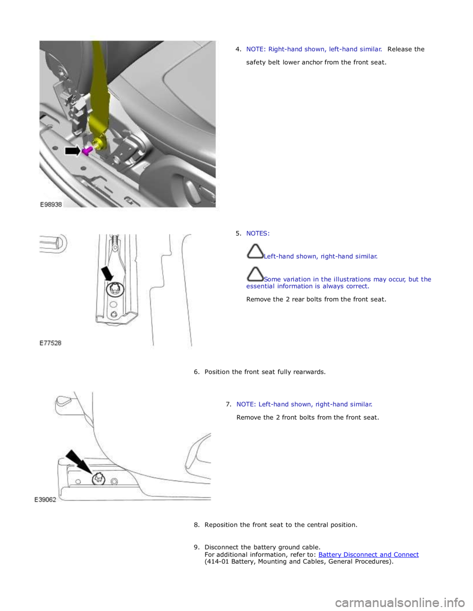
4. NOTE: Right-hand shown, left-hand similar. Release the
safety belt lower anchor from the front seat.
5. NOTES:
Left-hand shown, right-hand similar.
Some variation in the illustrations may occur, but the
essential information is always correct.
Remove the 2 rear bolts from the front seat.
6. Position the front seat fully rearwards.
7. NOTE: Left-hand shown, right-hand similar.
Remove the 2 front bolts from the front seat.
8. Reposition the front seat to the central position.
9. Disconnect the battery ground cable.
For additional information, refer to: Battery Disconnect and Connect (414-01 Battery, Mounting and Cables, General Procedures).
Page 2381 of 3039
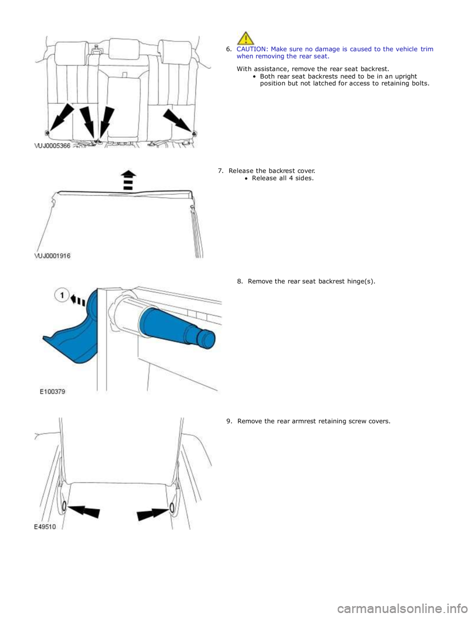
6. CAUTION: Make sure no damage is caused to the vehicle trim
when removing the rear seat.
With assistance, remove the rear seat backrest.
Both rear seat backrests need to be in an upright
position but not latched for access to retaining bolts.
7. Release the backrest cover.
Release all 4 sides.
8. Remove the rear seat backrest hinge(s).
9. Remove the rear armrest retaining screw covers.
Page 2447 of 3039
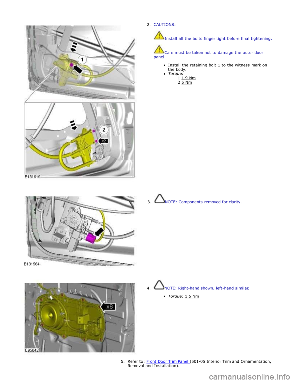
2. CAUTIONS:
Install all the bolts finger tight before final tightening.
Care must be taken not to damage the outer door
panel.
Install the retaining bolt 1 to the witness mark on
the body.
Torque:
1 1.9 Nm 2 5 Nm
3. NOTE: Components removed for clarity.
4. NOTE: Right-hand shown, left-hand similar.
Torque: 1.5 Nm
5. Refer to: Front Door Trim Panel (501-05 Interior Trim and Ornamentation, Removal and Installation).
Page 2448 of 3039

Instrument panel retaining bolts 20 15 - Floor console retaining nuts 5 - 44 Instrument panel support brackets retaining bolts 9 - 80 Instrument panel support brackets retaining nuts 9 - 80
Page 2466 of 3039
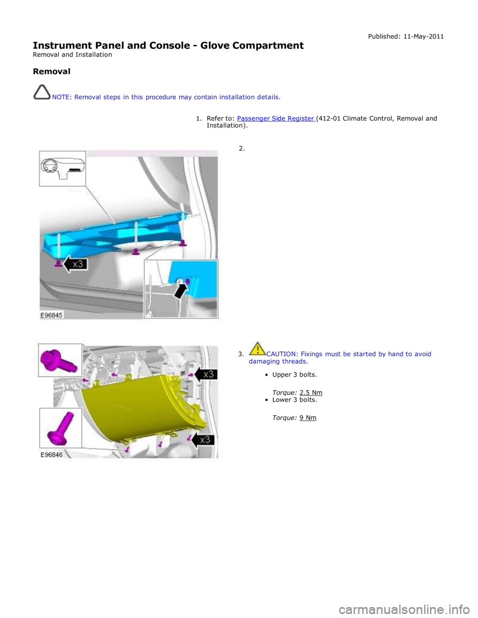
Instrument Panel and Console - Glove Compartment
Removal and Installation
Removal
NOTE: Removal steps in this procedure may contain installation details. Published: 11-May-2011
1. Refer to: Passenger Side Register (412-01 Climate Control, Removal and Installation).
2.
3. CAUTION: Fixings must be started by hand to avoid
damaging threads.
Upper 3 bolts.
Torque: 2.5 Nm Lower 3 bolts.
Torque: 9 Nm