Module JAGUAR XFR 2010 1.G Workshop Manual
[x] Cancel search | Manufacturer: JAGUAR, Model Year: 2010, Model line: XFR, Model: JAGUAR XFR 2010 1.GPages: 3039, PDF Size: 58.49 MB
Page 710 of 3039
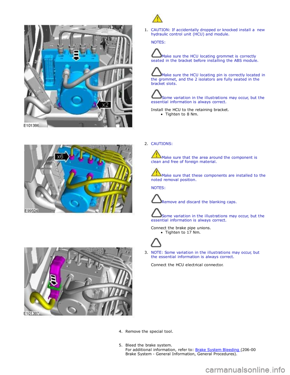
1. CAUTION: If accidentally dropped or knocked install a new
hydraulic control unit (HCU) and module.
NOTES:
Make sure the HCU locating grommet is correctly
seated in the bracket before installing the ABS module.
Make sure the HCU locating pin is correctly located in
the grommet, and the 2 isolators are fully seated in the
bracket slots.
Some variation in the illustrations may occur, but the
essential information is always correct.
Install the HCU to the retaining bracket.
Tighten to 8 Nm.
2. CAUTIONS:
Make sure that the area around the component is
clean and free of foreign material.
Make sure that these components are installed to the
noted removal position.
NOTES:
Remove and discard the blanking caps.
Some variation in the illustrations may occur, but the
essential information is always correct.
Connect the brake pipe unions.
Tighten to 17 Nm.
3. NOTE: Some variation in the illustrations may occur, but
the essential information is always correct.
Connect the HCU electrical connector.
4. Remove the special tool.
5. Bleed the brake system.
For additional information, refer to: Brake System Bleeding (206-00 Brake System - General Information, General Procedures).
Page 718 of 3039
Steering System - General Information - Steering System
Diagnosis and Testing
Principle of Operation Published: 11-May-2011
For a detailed description of the steering system operation, refer to the relevant Description and Operation sections of the
workshop manual. REFER to:
Power Steering (211-02 Power Steering, Description and Operation), Power Steering (211-02 Power Steering, Description and Operation), Power Steering (211-02 Power Steering, Description and Operation), Steering Linkage (211-03 Steering Linkage, Description and Operation), Steering Linkage (211-03 Steering Linkage, Description and Operation), Steering Linkage (211-03 Steering Linkage, Description and Operation), Steering Column (211-04 Steering Column, Description and Operation), Steering Column (211-04 Steering Column, Description and Operation), Steering Column (211-04 Steering Column, Description and Operation), Steering Column Switches (211-05 Steering Column Switches, Description and Operation), Steering Column Switches (211-05 Steering Column Switches, Description and Operation), Steering Column Switches (211-05 Steering Column Switches, Description and Operation).
Inspection and Verification
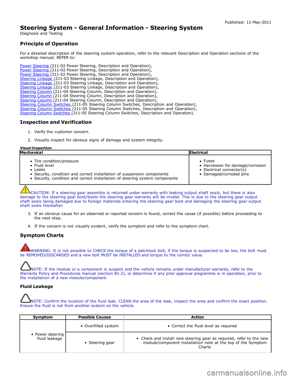
1. Verify the customer concern.
2. Visually inspect for obvious signs of damage and system integrity.
Visual Inspection
Mechanical Electrical
Tire condition/pressure
Fluid level
Leaks
Security, condition and correct installation of suspension components
Security, condition and correct installation of steering system components
Fuses
Harnesses for damage/corrosion
Electrical connector(s)
Damaged/corroded pins
CAUTION: If a steering gear assembly is returned under warranty with leaking output shaft seals, but there is also
damage to the steering gear boot/boots the steering gear warranty will be invalid. This is due to the steering gear output
shaft seals being damaged due to foreign materials entering the steering gear boot and damaging the steering gear output
shaft seals thereafter.
3. If an obvious cause for an observed or reported concern is found, correct the cause (if possible) before proceeding to
the next step.
4. If the concern is not visually evident, verify the symptom and refer to the symptom chart.
Symptom Charts
WARNING: It is not possible to CHECK the torque of a patchlock bolt, if the torque is suspected to be low, the bolt must
be REMOVED/DISCARDED and a new bolt MUST be INSTALLED and torque to the correct value.
NOTE: If the module or a component is suspect and the vehicle remains under manufacturer warranty, refer to the
Warranty Policy and Procedures manual (section B1.2), or determine if any prior approval programme is in operation, prior to
the installation of a new module/component.
Fluid Leakage
NOTE: Confirm the location of the fluid leak. CLEAN the area of the leak, inspect the area and confirm the exact position.
Ensure the fluid is not from another system on the vehicle.
Symptom Possible Causes Action
Power steering
fluid leakage
Overfilled system
Correct the fluid level as required
Steering gear
Check and install new steering gear as required, refer to the new
module/component installation note at the top of the Symptom
Charts
Page 719 of 3039
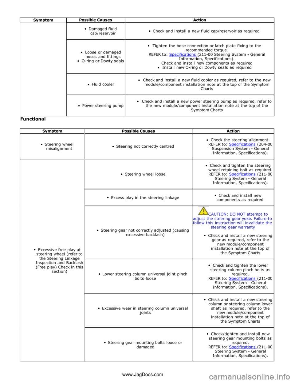
Symptom Possible Causes Action
Damaged fluid
cap/reservoir
Check and install a new fluid cap/reservoir as required
Loose or damaged
hoses and fittings
O-ring or Dowty seals
Tighten the hose connection or latch plate fixing to the
recommended torque.
REFER to: Specifications (211-00 Steering System - General Information, Specifications).
Check and install new components as required
Install new O-ring or Dowty seals as required
Fluid cooler
Check and install a new fluid cooler as required, refer to the new
module/component installation note at the top of the Symptom
Charts
Power steering pump
Check and install a new power steering pump as required, refer to
the new module/component installation note at the top of the
Symptom Charts Functional
Symptom Possible Causes Action
Steering wheel
misalignment
Steering not correctly centred
Check the steering alignment.
REFER to: Specifications (204-00 Suspension System - General
Information, Specifications).
Excessive free play at
steering wheel (refer to
the Steering Linkage
Inspection and Backlash
(Free play) Check in this
section)
Steering wheel loose
Check and tighten the steering
wheel retaining bolt as required.
REFER to: Specifications (211-00 Steering System - General
Information, Specifications).
Excess play in the steering linkage
Check and install new
components as required
Steering gear not correctly adjusted (causing
excessive backlash)
CAUTION: DO NOT attempt to
adjust the steering gear yoke. Failure to
follow this instruction will invalidate the
steering gear warranty
Check and install a new steering
gear as required, refer to the
new module/component
installation note at the top of
the Symptom Charts
Lower steering column universal joint pinch
bolts loose
Check and tighten the lower
steering column pinch bolts as
required.
REFER to: Specifications (211-00 Steering System - General
Information, Specifications).
Excessive wear in steering column universal
joints
Check and install a new steering
column or steering column lower
shaft as required, refer to the
new module/component
installation note at the top of
the Symptom Charts
Steering gear mounting bolts loose or
damaged
Check/tighten and install new
steering gear mounting bolts as
required.
REFER to: Specifications (211-00 Steering System - General
Information, Specifications). www.JagDocs.com
Page 720 of 3039
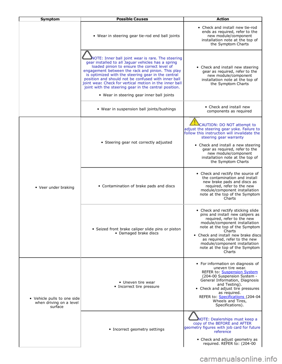
Symptom Possible Causes Action
Wear in steering gear tie-rod end ball joints
Check and install new tie-rod
ends as required, refer to the
new module/component
installation note at the top of
the Symptom Charts
NOTE: Inner ball joint wear is rare. The steering
gear installed to all Jaguar vehicles has a spring
loaded pinion to ensure the correct level of
engagement between the rack and pinion. This play
is optimized with the steering gear in the central
position and should not be confused with inner ball
joint wear. Check for vertical motion in the inner ball
joint with the steering gear in the central position.
Wear in steering gear inner ball joints
Check and install new steering
gear as required, refer to the
new module/component
installation note at the top of
the Symptom Charts
Wear in suspension ball joints/bushings
Check and install new
components as required
Veer under braking
Steering gear not correctly adjusted
CAUTION: DO NOT attempt to
adjust the steering gear yoke. Failure to
follow this instruction will invalidate the
steering gear warranty
Check and install a new steering
gear as required, refer to the
new module/component
installation note at the top of
the Symptom Charts
Contamination of brake pads and discs
Check and rectify the source of
the contamination and install
new brake pads and discs as
required, refer to the new
module/component installation
note at the top of the Symptom
Charts
Seized front brake caliper slide pins or piston
Damaged brake discs
Check and rectify sticking slide
pins and install new calipers as
required, refer to the new
module/component installation
note at the top of the Symptom
Charts
Check and install new brake discs
as required, refer to the new
module/component installation
note at the top of the Symptom
Charts
Vehicle pulls to one side
when driving on a level
surface
Uneven tire wear
Incorrect tire pressure
For information on diagnosis of
uneven tire wear.
REFER to: Suspension System (204-00 Suspension System -
General Information, Diagnosis
and Testing).
Check and adjust tire pressures
as required.
REFER to: Specifications (204-04 Wheels and Tires,
Specifications).
Incorrect geometry settings
NOTE: Dealerships must keep a
copy of the BEFORE and AFTER
geometry figures with job card for future
reference
Check and adjust geometry as
required. REFER to: (204-00
Page 721 of 3039
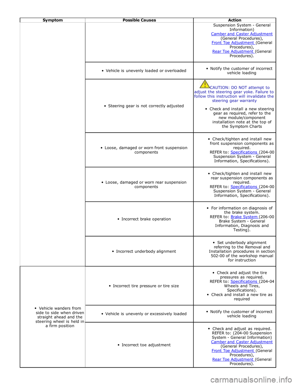
Symptom Possible Causes Action Suspension System - General
Information)
Camber and Caster Adjustment (General Procedures),
Front Toe Adjustment (General Procedures),
Rear Toe Adjustment (General Procedures).
Vehicle is unevenly loaded or overloaded
Notify the customer of incorrect
vehicle loading
Steering gear is not correctly adjusted
CAUTION: DO NOT attempt to
adjust the steering gear yoke. Failure to
follow this instruction will invalidate the
steering gear warranty
Check and install a new steering
gear as required, refer to the
new module/component
installation note at the top of
the Symptom Charts
Loose, damaged or worn front suspension
components
Check/tighten and install new
front suspension components as
required.
REFER to: Specifications (204-00 Suspension System - General
Information, Specifications).
Loose, damaged or worn rear suspension
components
Check/tighten and install new
rear suspension components as
required.
REFER to: Specifications (204-00 Suspension System - General
Information, Specifications).
Incorrect brake operation
For information on diagnosis of
the brake system.
REFER to: Brake System (206-00 Brake System - General
Information, Diagnosis and
Testing).
Incorrect underbody alignment
Set underbody alignment
referring to the Removal and
Installation procedures in section
502-00 of the workshop manual
for instruction
Vehicle wanders from
side to side when driven
straight ahead and the
steering wheel is held in
a firm position
Incorrect tire pressure or tire size
Check and adjust the tire
pressures as required.
REFER to: Specifications (204-04 Wheels and Tires,
Specifications).
Check and install a new tire as
required
Vehicle is unevenly or excessively loaded
Notify the customer of incorrect
vehicle loading
Incorrect toe adjustment
Check and adjust as required.
REFER to: (204-00 Suspension
System - General Information)
Camber and Caster Adjustment (General Procedures),
Front Toe Adjustment (General Procedures),
Rear Toe Adjustment (General Procedures).
Page 744 of 3039

1 Return fluid control groove 2 Radial groove 3 Feed fluid control groove 4 Radial groove 5 Axial groove 6 Feed fluid control edge 7 Feed fluid radial groove 8 Return fluid control edge 9 Return fluid chamber 10 Cut-off valve 11 Radial groove 12 Servotronic transducer valve 13 Feed fluid radial groove 14 Radial groove 15 Orifice 16 Balls 17 Compression spring 18 Torsion bar 19 Power steering fluid reservoir 20 Valve rotor 21 Reaction piston 22 Reaction chamber 23 Centering piece 24 Pressure relief/flow limiting valve 25 Power steering pump 26 Inner tie-rod 27 Pinion 28 Valve sleeve 29 Steering gear rack 30 Steering gear housing 31 Power assist cylinder - right 32 Piston 33 Power assist cylinder - left When the steering wheel is turned to the right, the steering rack and piston moves to the left in the piston bore. The valve
rotor is rotated to the right (clockwise) and pressurized fluid is directed over the further opened feed fluid control edges and to
the associated axial grooves, the radial groove and via an external pipe to the left power assist cylinder chamber. The pressure
applied to the piston from the left power assist cylinder chamber provides the hydraulic assistance.
An adaptable pressure build-up is achieved by the partially or fully closed feed fluid control edges restricting or preventing a
connection between the fluid pressure inlet and the other axial grooves connected to the radial groove.
Simultaneously, the fluid pressure outlet to the pressurized axial grooves are restricted or partially restricted by the closing
return fluid control edges. The fluid displaced by the piston from the right power assist cylinder chamber, flows through an
external pipe to the radial grooves. From there the fluid passes to the associated axial grooves and on to the return fluid
control grooves, via the further opened return fluid control edges.
The return flow of fluid to the reservoir passes via interconnecting bores which lead to the return fluid chamber. When the
steering wheel is turned to the left the operating sequence is as above but the pressure is applied to the opposite side of the
piston.
Servotronic Operation
The Servotronic software contains a number of steering maps which are selected via the car configuration file depending on the
vehicle mode and tire fitment.
If a failure of the Servotronic valve or software occurs, the system will suspend Servotronic assistance and only normal power
steering wheel be available. Fault codes relating to the fault are stored, but no warning lamps are illuminated and the driver
may be aware of the steering being 'heavier' than usual.
When the vehicle is manoeuvred into and out of a parking space (or other similar manoeuvre), the Servotronic software uses
road speed data from the ABS module to determine the vehicle speed, which in this case will be slow or stationary. The
Servotronic software analyses the signals and outputs an appropriate control current to the Servotronic transducer valve. The
Servotronic valve closes and prevents fluid flowing from the feed fluid radial groove to the reaction chamber. An orifice also
Page 747 of 3039
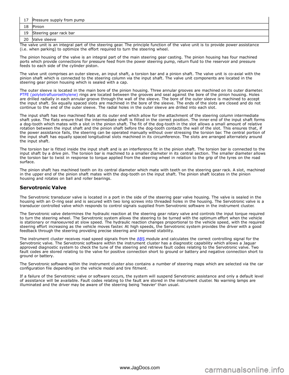
18 Pinion 19 Steering gear rack bar 20 Valve sleeve The valve unit is an integral part of the steering gear. The principle function of the valve unit is to provide power assistance
(i.e. when parking) to optimize the effort required to turn the steering wheel.
The pinion housing of the valve is an integral part of the main steering gear casting. The pinion housing has four machined
ports which provide connections for pressure feed from the power steering pump, return fluid to the reservoir and pressure
feeds to each side of the cylinder piston.
The valve unit comprises an outer sleeve, an input shaft, a torsion bar and a pinion shaft. The valve unit is co-axial with the
pinion shaft which is connected to the steering column via the input shaft. The valve unit components are located in the
steering gear pinion housing which is sealed with a cap.
The outer sleeve is located in the main bore of the pinion housing. Three annular grooves are machined on its outer diameter.
PTFE (polytetrafluoroethylene) rings are located between the grooves and seal against the bore of the pinion housing. Holes
are drilled radially in each annular groove through the wall of the sleeve. The bore of the outer sleeve is machined to accept
the input shaft. Six equally spaced slots are machined in the bore of the sleeve. The ends of the slots are closed and do not
continue to the end of the outer sleeve. The radial holes in the outer sleeve are drilled into each slot.
The input shaft has two machined flats at its outer end which allow for the attachment of the steering column intermediate
shaft yoke. The flats ensure that the intermediate shaft is fitted in the correct position. The inner end of the input shaft forms
a dog-tooth which mates with a slot in the pinion shaft. The fit of the dog-tooth in the slot allows a small amount of relative
rotation between the input shaft and the pinion shaft before the dog-tooth contacts the wall of the slot. This ensures that, if
the power assistance fails, the steering can be operated manually without over stressing the torsion bar. The central portion of
the input shaft has equally spaced longitudinal slots machined in its circumference. The slots are arranged alternately around
the input shaft.
The torsion bar is fitted inside the input shaft and is an interference fit in the pinion shaft. The torsion bar is connected to the
input shaft by a drive pin. The torsion bar is machined to a smaller diameter in its central section. The smaller diameter allows
the torsion bar to twist in response to torque applied from the steering wheel in relation to the grip of the tyres on the road
surface.
The pinion shaft has machined teeth on its central diameter which mate with teeth on the steering gear rack. A slot, machined
in the upper end of the pinion shaft mates with the dog-tooth on the input shaft. The pinion shaft locates in the pinion
housing and rotates on ball and roller bearings.
Servotronic Valve
The Servotronic transducer valve is located in a port in the side of the steering gear valve housing. The valve is sealed in the
housing with an O-ring seal and is secured with two long screws into threaded holes in the housing. The Servotronic valve is a
transducer controlled valve which responds to control signals supplied from Servotronic software in the instrument cluster.
The Servotronic valve determines the hydraulic reaction at the steering gear rotary valve and controls the input torque required
to turn the steering wheel. The Servotronic system allows the steering to be turned with the optimum effort when the vehicle
is stationary or manoeuvred at slow speed. The hydraulic reaction changes proportional to the vehicle speed, with the required
steering effort increasing as the vehicle moves faster. At high speeds, the Servotronic system provides the driver with a good
feedback through the steering providing precise steering and improved stability.
The instrument cluster receives road speed signals from the ABS module and calculates the correct controlling signal for the Servotronic valve. The Servotronic software within the instrument cluster has a diagnostic capability which allows a Jaguar
approved diagnostic system to check the tune of the steering and retrieve fault codes relating to the Servotronic valve. Two
fault codes are stored relating to the valve for positive connection short to ground or battery and negative connection short to
ground or battery.
The Servotronic software within the instrument cluster also contains a number of steering maps which are selected via the car
configuration file depending on the vehicle model and tire fitment.
If a failure of the Servotronic valve or software occurs, the system will suspend Servotronic assistance and only a default level
of assistance will be available. Fault codes relating to the fault are stored in the instrument cluster. No warning lamps are
illuminated and the driver may be aware of the steering being 'heavier' than usual.
www.JagDocs.com
Page 777 of 3039

Steering Column - Steering Column - Overview
Description and Operation
OVERVIEW Published: 11-May-2011
The steering column comprises the upper column assembly, the lower column assembly and the steering wheel. The 3
components are positively connected together to pass driver rotary input from the steering wheel to a linear output of the
steering rack.
The upper column assembly contains electrical adjustment for steering wheel reach and rake, the electric steering lock
mechanism and the steering angle sensor. Steering adjustment memory positions are stored in the driver's seat module.
The electric steering column is a standard fitment on all models. The upper column assembly contains electrical adjustment for
steering wheel reach and rake, the electric column lock mechanism and the steering angle sensor. Steering adjustment memory
positions are stored in the driver's seat module. The column also features a 'tilt away' function which moves the steering
column away from the driver allowing easier exit and entry to the vehicle.
Column adjustment is provided by a single motor for both reach and rake adjustment. Operation of the column adjustment is
controlled by a four way joystick type switch located in the column lower shroud. Column adjustment is an integral part of the
driver position memory system.
www.JagDocs.com
Page 779 of 3039
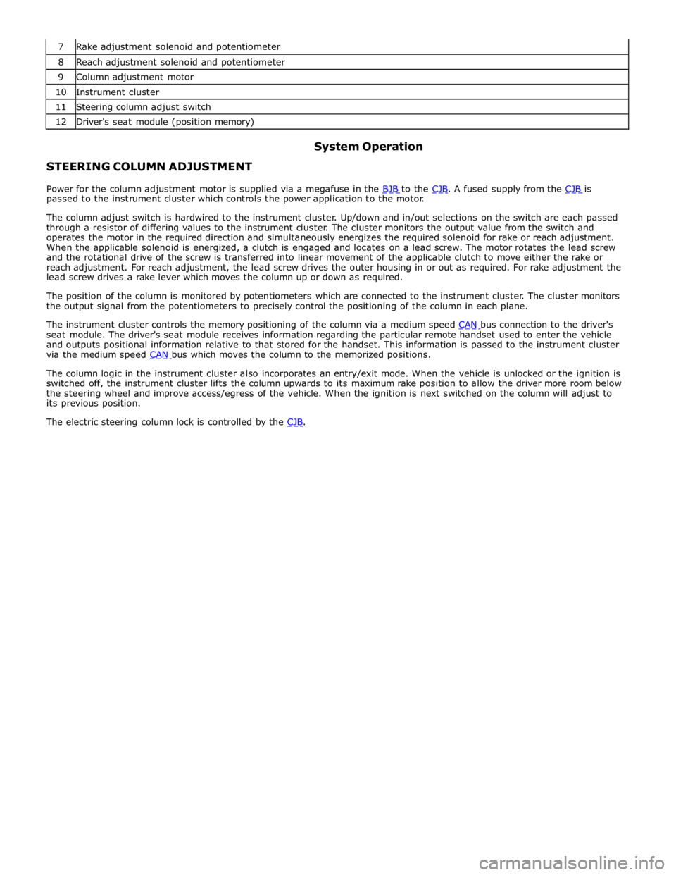
8 Reach adjustment solenoid and potentiometer 9 Column adjustment motor 10 Instrument cluster 11 Steering column adjust switch 12 Driver's seat module (position memory)
STEERING COLUMN ADJUSTMENT System Operation
Power for the column adjustment motor is supplied via a megafuse in the BJB to the CJB. A fused supply from the CJB is passed to the instrument cluster which controls the power application to the motor.
The column adjust switch is hardwired to the instrument cluster. Up/down and in/out selections on the switch are each passed
through a resistor of differing values to the instrument cluster. The cluster monitors the output value from the switch and
operates the motor in the required direction and simultaneously energizes the required solenoid for rake or reach adjustment.
When the applicable solenoid is energized, a clutch is engaged and locates on a lead screw. The motor rotates the lead screw
and the rotational drive of the screw is transferred into linear movement of the applicable clutch to move either the rake or
reach adjustment. For reach adjustment, the lead screw drives the outer housing in or out as required. For rake adjustment the
lead screw drives a rake lever which moves the column up or down as required.
The position of the column is monitored by potentiometers which are connected to the instrument cluster. The cluster monitors
the output signal from the potentiometers to precisely control the positioning of the column in each plane.
The instrument cluster controls the memory positioning of the column via a medium speed CAN bus connection to the driver's seat module. The driver's seat module receives information regarding the particular remote handset used to enter the vehicle
and outputs positional information relative to that stored for the handset. This information is passed to the instrument cluster
via the medium speed CAN bus which moves the column to the memorized positions.
The column logic in the instrument cluster also incorporates an entry/exit mode. When the vehicle is unlocked or the ignition is
switched off, the instrument cluster lifts the column upwards to its maximum rake position to allow the driver more room below
the steering wheel and improve access/egress of the vehicle. When the ignition is next switched on the column will adjust to
its previous position.
The electric steering column lock is controlled by the CJB.
Page 782 of 3039
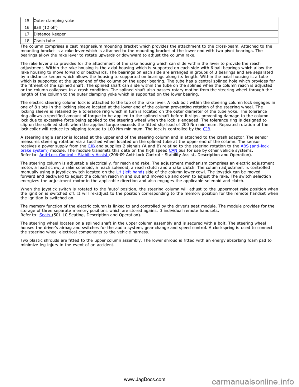
16 Ball (12 off) 17 Distance keeper 18 Crash tube The column comprises a cast magnesium mounting bracket which provides the attachment to the cross-beam. Attached to the
mounting bracket is a rake lever which is attached to the mounting bracket at the lower end with two pivot bearings. The
bearings allow the rake lever to rotate upwards or downward to adjust the column rake.
The rake lever also provides for the attachment of the rake housing which can slide within the lever to provide the reach
adjustment. Within the rake housing is the axial housing which is supported on each side with 6 ball bearings which allow the
rake housing to move forward or backwards. The bearings on each side are arranged in groups of 3 bearings and are separated
by a distance keeper which allows the housing to supported on bearings along its length. Within the axial housing is a tube
which is supported at the upper end of the column on the upper bearing. The tube has a central splined hole which provides for
the fitment of the splined shaft. The splined shaft can slide within the tube on the splines when the column reach is adjusted
or the column collapses in a crash condition. The splined shaft also passes rotary motion from the steering wheel through the
length of the column to the outer clamping yoke which is supported on the lower bearing.
The electric steering column lock is attached to the top of the rake lever. A lock bolt within the steering column lock engages in
one of 8 slots in the locking sleeve located at the lower end of the column preventing rotation of the steering wheel. The
locking sleeve is retained by a tolerance ring which in turn is located on the outer diameter of the tube yoke. The tolerance
ring allows a specified amount of torque to be applied to the splined shaft before it slips, preventing damage to the column
lock due to excessive force being applied to the steering wheel when the lock is engaged. The tolerance ring is designed to
slip on the splined shaft when the applied torque exceeds the fitted slip load of 200 Nm minimum. Repeated rotation of the
lock collar will reduce its slipping torque to 100 Nm minimum. The lock is controlled by the CJB.
A steering angle sensor is located at the upper end of the steering column and is attached to the crash adaptor. The sensor
measures steering rotation via a toothed wheel located on the splined tube at the upper end of the column. The sensor
receives a power supply from the CJB and supplies 2 signals (A and B) relating to the steering rotation to the ABS (anti-lock brake system) module. The module transmits this data on the high speed CAN bus for use by other vehicle systems. Refer to: Anti-Lock Control - Stability Assist (206-09 Anti-Lock Control - Stability Assist, Description and Operation).
The steering column is adjustable electrically, for reach and rake. The adjustment mechanism comprises an electric adjustment
motor, a lead screw, a rake solenoid, a reach solenoid, a reach clutch and a rake clutch. The column adjustment is controlled
manually using a joystick switch located on the LH (left-hand) side of the column lower cowl. The joystick can be moved
forward and backward to adjust the column reach in and out and moved up and down to adjust the rake. The switch selection
energizes the adjustment motor in the applicable direction and also engages the applicable solenoid and clutch.
When the joystick switch is rotated to the 'auto' position, the steering column will adjust to the uppermost rake position when
the ignition is switched off. It will re-adjust to the position corresponding to the memory position for the remote handset when
the ignition is switched on.
The memory function of the electric column is linked to and controlled by the driver's seat module. The module provides for the
storage of three separate memory positions which are stored against 3 individual remote handsets.
Refer to: Seats (501-10 Seating, Description and Operation).
The steering wheel locates on a splined shaft in the upper column assembly and is secured with a bolt. The steering wheel
houses the driver's airbag and switches for the audio system, gear change and speed control. A clockspring is used to connect
the steering wheel electrical components to the vehicle harness.
Two plastic shrouds are fitted to the upper column assembly. The lower shroud is fitted with an energy absorbing foam pad to
minimize leg injury in the event of an accident.
www.JagDocs.com