Module JAGUAR XFR 2010 1.G Workshop Manual
[x] Cancel search | Manufacturer: JAGUAR, Model Year: 2010, Model line: XFR, Model: JAGUAR XFR 2010 1.GPages: 3039, PDF Size: 58.49 MB
Page 651 of 3039

Stoplamp Switch
The stoplamp switch is mounted on the brake pedal box. One of the prerequisites for releasing the parking brake is that the
foot brake is applied. The EPB module is able to determine the position of the footbrake by monitoring the status of the
stoplamp switch via a hardwired electrical connection.
The stoplamp switch also forms part of:
The ABS. Refer to: Anti-Lock Control - Stability Assist (206-09 Anti-Lock Control - Stability Assist, Description and Operation). The speed control system. For additional information, refer to:
Speed Control (310-03A, Description and Operation),
Speed Control (310-03B, Description and Operation),
Speed Control (310-03C, Description and Operation).
Page 653 of 3039

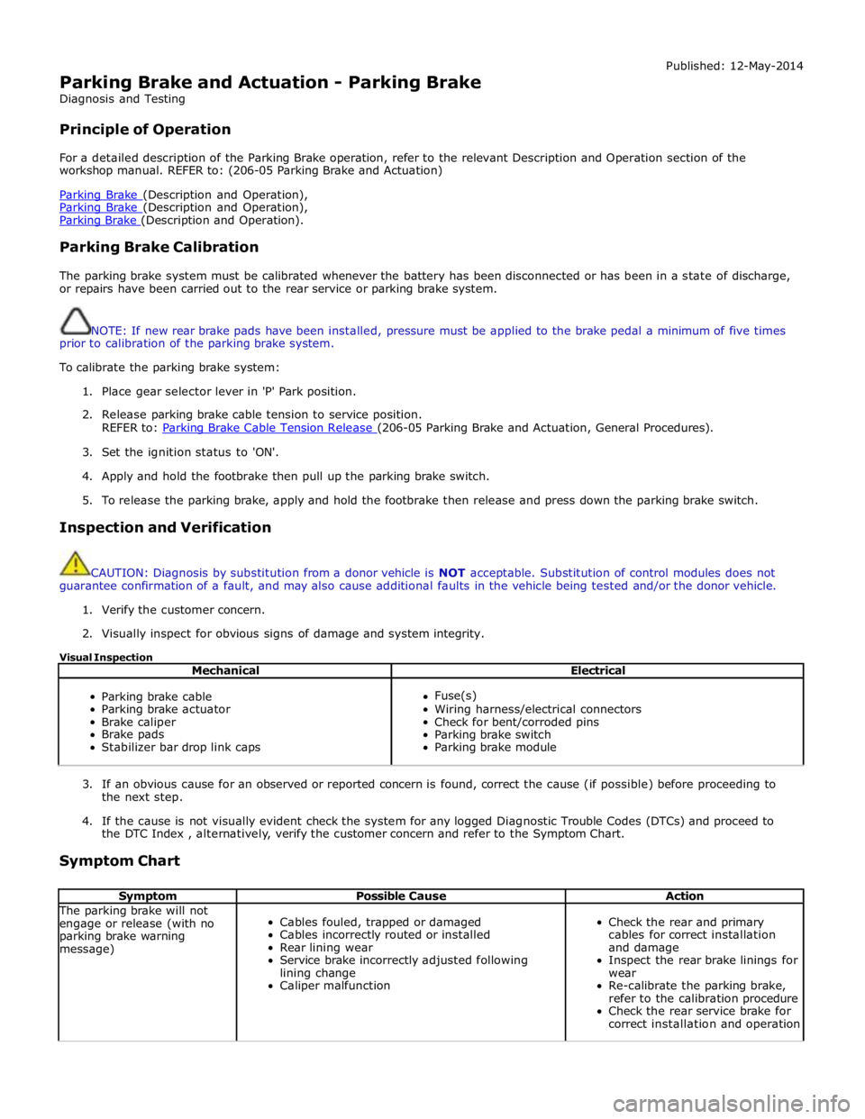
Parking Brake and Actuation - Parking Brake
Diagnosis and Testing
Principle of Operation Published: 12-May-2014
For a detailed description of the Parking Brake operation, refer to the relevant Description and Operation section of the
workshop manual. REFER to: (206-05 Parking Brake and Actuation)
Parking Brake (Description and Operation), Parking Brake (Description and Operation), Parking Brake (Description and Operation).
Parking Brake Calibration
The parking brake system must be calibrated whenever the battery has been disconnected or has been in a state of discharge,
or repairs have been carried out to the rear service or parking brake system.
NOTE: If new rear brake pads have been installed, pressure must be applied to the brake pedal a minimum of five times
prior to calibration of the parking brake system.
To calibrate the parking brake system:
1. Place gear selector lever in 'P' Park position.
2. Release parking brake cable tension to service position.
REFER to: Parking Brake Cable Tension Release (206-05 Parking Brake and Actuation, General Procedures).
3. Set the ignition status to 'ON'.
4. Apply and hold the footbrake then pull up the parking brake switch.
5. To release the parking brake, apply and hold the footbrake then release and press down the parking brake switch.
Inspection and Verification
CAUTION: Diagnosis by substitution from a donor vehicle is NOT acceptable. Substitution of control modules does not
guarantee confirmation of a fault, and may also cause additional faults in the vehicle being tested and/or the donor vehicle.
1. Verify the customer concern.
2. Visually inspect for obvious signs of damage and system integrity.
Visual Inspection
Mechanical Electrical
Parking brake cable
Parking brake actuator
Brake caliper
Brake pads
Stabilizer bar drop link caps
Fuse(s)
Wiring harness/electrical connectors
Check for bent/corroded pins
Parking brake switch
Parking brake module
3. If an obvious cause for an observed or reported concern is found, correct the cause (if possible) before proceeding to
the next step.
4. If the cause is not visually evident check the system for any logged Diagnostic Trouble Codes (DTCs) and proceed to
the DTC Index , alternatively, verify the customer concern and refer to the Symptom Chart.
Symptom Chart
Symptom Possible Cause Action The parking brake will not
engage or release (with no
parking brake warning
message)
Cables fouled, trapped or damaged
Cables incorrectly routed or installed
Rear lining wear
Service brake incorrectly adjusted following
lining change
Caliper malfunction
Check the rear and primary
cables for correct installation
and damage
Inspect the rear brake linings for
wear
Re-calibrate the parking brake,
refer to the calibration procedure
Check the rear service brake for
correct installation and operation
Page 654 of 3039

Symptom Possible Cause Action The parking brake will not
engage or release (with
parking brake warning
message)
Cables fouled, trapped or damaged
Cables incorrectly routed or installed
Rear lining wear
Actuator malfunction
Caliper malfunction
Check the rear and primary
cables for correct installation
and damage
Inspect the rear brake linings for
wear
Re-calibrate the parking brake,
refer to the calibration procedure
Check the rear service brake for
correct installation and operation No communication with the
parking brake module
Fuse
Module off Bus
CAN network error
Parking brake module fault
Check fuses
Ensure battery is fully charged
and in serviceable condition.
Check battery voltage at parking
brake module
Check CAN network using
manufacturer approved
diagnostic system 'Park brake Fault' displayed on
message center with
associated warning lamps
Parking brake system fault
Check the parking brake module
for DTCs and refer to DTC Index Brakes drag
Parking brake not re-calibrated after battery has
been disconnected or has been in a state of
discharge, or repairs have been carried out to
the rear service or parking brake system
Service brake system fault
Re-calibrate parking brake, refer
to the calibration procedure
Check the service brake for
correct operation DTC Index
For a list of diagnostic trouble codes that could be logged on this vehicle, please refer to Section 100-00.
REFER to: Diagnostic Trouble Code (DTC) Index - DTC: Electric Parking Brake (PBM) (100-00 General Information, Description and Operation).
Page 656 of 3039

3. WARNING: Failure to follow this instruction may result in a
diagnostic trouble code (DTC) being generated.
Disconnect the 2 electrical connectors from the parking
brake module, in the sequence illustrated.
4. NOTE: Some variation in the illustrations may occur,
but the essential information is always correct.
Connect the special tool to the parking brake module.
5. Release the parking brake cable tension.
An audible 'click', signals complete parking brake cable
tension release.
6. Remove the special tool and carry out any necessary repairs on the
system.
Page 662 of 3039

Parking Brake and Actuation - Parking Brake Module
Removal and Installation
Removal
NOTE: Removal steps in this procedure may contain installation details. Published: 11-May-2011
1. Refer to: Battery Disconnect and Connect (414-01 Battery, Mounting and Cables, General Procedures).
2. Refer to: Loadspace Trim Panel RH (501-05 Interior Trim and Ornamentation, Removal and Installation).
Installation
3. Torque: 4 Nm
1. To install, reverse the removal position
2. Configure the electronic parking brake (EPB) using the diagnostic tool.
Page 668 of 3039

Published: 11-May-2011
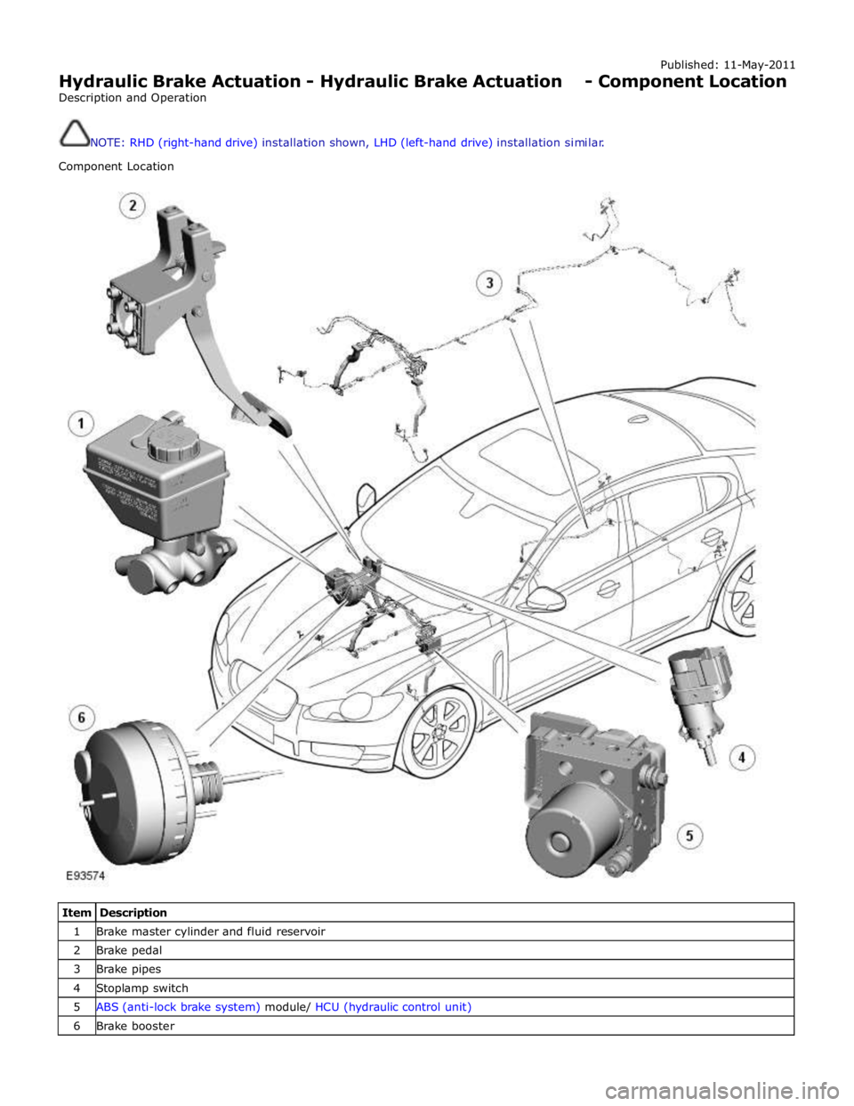
Hydraulic Brake Actuation - Hydraulic Brake Actuation - Component Location
Description and Operation
NOTE: RHD (right-hand drive) installation shown, LHD (left-hand drive) installation similar.
Component Location
Item Description 1 Brake master cylinder and fluid reservoir 2 Brake pedal 3 Brake pipes 4 Stoplamp switch 5 ABS (anti-lock brake system) module/ HCU (hydraulic control unit) 6 Brake booster
Page 673 of 3039

1 LH (left-hand) front brake 2 RH (right-hand) rear brake 3 LH rear brake 4 RH front brake 5 Primary circuit inlet port 6 Secondary circuit inlet port The ABS module is located in the passenger side, rear engine bay and incorporates the HCU. The HCU is a four channel unit that modulates the supply of hydraulic pressure to the brakes under control of the ABS module.
The primary and secondary outlets of the master cylinder are connected to the primary and secondary circuits within the HCU. The primary circuit in the HCU has separate outlet ports to the RH front and LH rear brakes. The secondary circuit in the HCU has separate outlet ports to the LH front and RH rear brakes.
Page 674 of 3039

CAUTION: The ABS module and the HCU are a single unit and must not be separated.
HCU Schematic Diagram
Item Description 1 Brake booster 2 Primary circuit 3 Secondary circuit 4 HCU
Page 691 of 3039

Published: 02-Sep-2011
Anti-Lock Control - Stability Assist - Anti-Lock Control - Stability Assist - Component Location
Description and Operation
NOTE: RHD (right-hand drive) installation shown, LHD (left-hand drive) installation similar.
Component Location
Item Description 1 ABS (anti-lock brake system) module 2 RH (right-hand) front wheel speed sensor 3 Instrument cluster 4 Steering angle sensor 5 Yaw rate and lateral acceleration sensor 6 RH rear wheel speed sensor 7 LH (left-hand) rear wheel speed sensor 8 LH front wheel speed sensor
Page 692 of 3039

Published: 11-May-2011
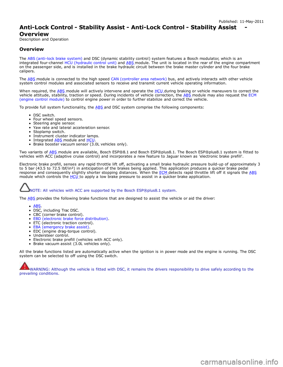
Anti-Lock Control - Stability Assist - Anti-Lock Control - Stability Assist - Overview
Description and Operation
Overview
The ABS (anti-lock brake system) and DSC (dynamic stability control) system features a Bosch modulator, which is an
integrated four-channel HCU (hydraulic control unit) and ABS module. The unit is located in the rear of the engine compartment on the passenger side, and is installed in the brake hydraulic circuit between the brake master cylinder and the four brake
calipers.
The ABS module is connected to the high speed CAN (controller area network) bus, and actively interacts with other vehicle system control modules and associated sensors to receive and transmit current vehicle operating information.
When required, the ABS module will actively intervene and operate the HCU during braking or vehicle maneuvers to correct the vehicle attitude, stability, traction or speed. During incidents of vehicle correction, the ABS module may also request the ECM (engine control module) to control engine power in order to further stabilize and correct the vehicle.
To provide full system functionality, the ABS and DSC system comprise the following components: DSC switch.
Four wheel speed sensors.
Steering angle sensor.
Yaw rate and lateral acceleration sensor.
Stoplamp switch.
Instrument cluster indicator lamps.
Integrated ABS module and HCU. Brake booster vacuum sensor (3.0L vehicles only).
Two variants of ABS module are available, Bosch ESP®8.1 and Bosch ESP®plus8.1. The Bosch ESP®plus8.1 system is fitted to vehicles with ACC (adaptive cruise control) and incorporates a new feature to Jaguar known as 'electronic brake prefill'.
Electronic brake prefill, senses any rapid throttle lift off, activating a small brake hydraulic pressure build-up of approximately 3
to 5 bar (43.5 to 72.5 lbf/in²) in anticipation of the brakes being applied. This application produces a quicker brake pedal
response and consequently slightly shorter stopping distances. When the ECM detects rapid throttle lift off it signals the ABS module which controls the HCU to apply a low brake pressure to assist in a quicker brake application.
NOTE: All vehicles with ACC are supported by the Bosch ESP®plus8.1 system.
The ABS provides the following brake functions that are designed to assist the vehicle or aid the driver: ABS. DSC, including Trac DSC.
CBC (corner brake control).
EBD (electronic brake force distribution).
ETC (electronic traction control).
EBA (emergency brake assist).
EDC (engine drag-torque control).
Understeer control.
Electronic brake prefill (vehicles with ACC only).
Brake vacuum assist (3.0L vehicles only).
All the brake functions listed are automatically active when the ignition is in power mode and the engine is running. The DSC
system can be selected to off using the DSC switch.
WARNING: Although the vehicle is fitted with DSC, it remains the drivers responsibility to drive safely according to the
prevailing conditions.