Engine JAGUAR XFR 2010 1.G Workshop Manual
[x] Cancel search | Manufacturer: JAGUAR, Model Year: 2010, Model line: XFR, Model: JAGUAR XFR 2010 1.GPages: 3039, PDF Size: 58.49 MB
Page 1177 of 3039
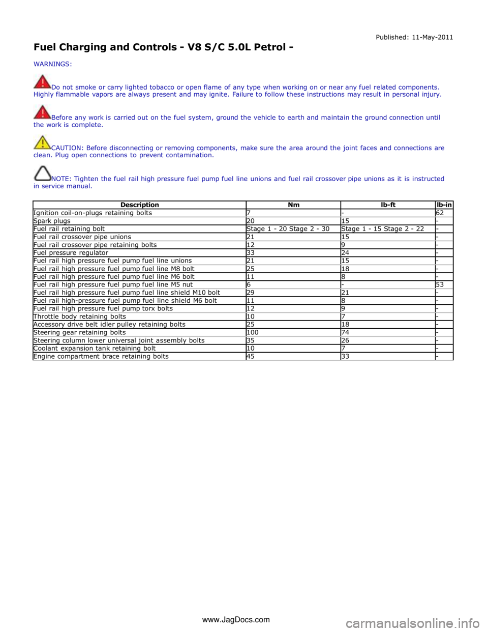
Fuel Charging and Controls - V8 S/C 5.0L Petrol -
WARNINGS: Published: 11-May-2011
Do not smoke or carry lighted tobacco or open flame of any type when working on or near any fuel related components.
Highly flammable vapors are always present and may ignite. Failure to follow these instructions may result in personal injury.
Before any work is carried out on the fuel system, ground the vehicle to earth and maintain the ground connection until
the work is complete.
CAUTION: Before disconnecting or removing components, make sure the area around the joint faces and connections are
clean. Plug open connections to prevent contamination.
NOTE: Tighten the fuel rail high pressure fuel pump fuel line unions and fuel rail crossover pipe unions as it is instructed
in service manual.
Description Nm lb-ft lb-in Ignition coil-on-plugs retaining bolts 7 - 62 Spark plugs 20 15 - Fuel rail retaining bolt Stage 1 - 20 Stage 2 - 30 Stage 1 - 15 Stage 2 - 22 - Fuel rail crossover pipe unions 21 15 - Fuel rail crossover pipe retaining bolts 12 9 - Fuel pressure regulator 33 24 - Fuel rail high pressure fuel pump fuel line unions 21 15 - Fuel rail high pressure fuel pump fuel line M8 bolt 25 18 - Fuel rail high pressure fuel pump fuel line M6 bolt 11 8 - Fuel rail high pressure fuel pump fuel line M5 nut 6 - 53 Fuel rail high pressure fuel pump fuel line shield M10 bolt 29 21 - Fuel rail high-pressure fuel pump fuel line shield M6 bolt 11 8 - Fuel rail high pressure fuel pump torx bolts 12 9 - Throttle body retaining bolts 10 7 - Accessory drive belt idler pulley retaining bolts 25 18 - Steering gear retaining bolts 100 74 - Steering column lower universal joint assembly bolts 35 26 - Coolant expansion tank retaining bolt 10 7 - Engine compartment brace retaining bolts 45 33 - www.JagDocs.com
Page 1180 of 3039
Published: 15-Mar-2013
Fuel Charging and Controls - V8 S/C 5.0L Petrol - Fuel Charging and Controls
- System Operation and Component Description
Description and Operation
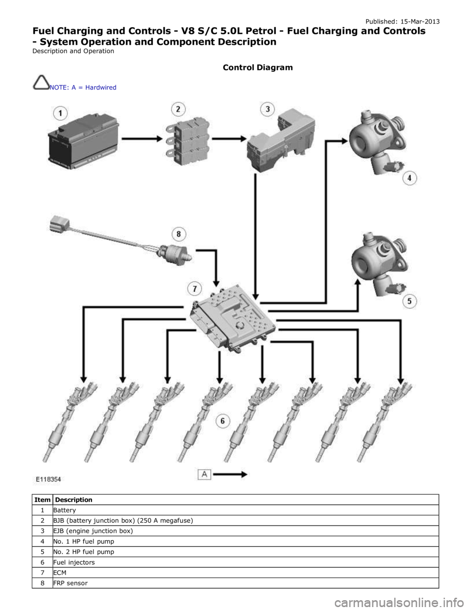
Control Diagram
NOTE: A = Hardwired
Item Description 1 Battery 2 BJB (battery junction box) (250 A megafuse) 3 EJB (engine junction box) 4 No. 1 HP fuel pump 5 No. 2 HP fuel pump 6 Fuel injectors 7 ECM 8 FRP sensor
Page 1182 of 3039

1 Crankshaft 2 Auxiliary drive chain 3 Auxiliary camshaft 4 Tappet 5 HP fuel pump 6 Acoustic cover The two HP fuel pumps are identical mechanically-driven pumps installed on the RH side of the sump body, behind the generator. An O-ring seals each of the HP fuel pumps in the sump body. The rear HP fuel pump is identified as No. 1 pump; the
front HP fuel pump is identified as No. 2 pump. An acoustic cover is installed on each of the HP fuel pumps.
The HP fuel pumps are single-plunger pumps. The plunger of each pump extends through the sump body and the carrier of the
auxiliary camshaft. A tappet on the end each plunger is operated by a two-lobe cam on the auxiliary camshaft. A spring
installed on the outside of the plunger ensures the plunger and tappet remain in contact with the cam.
The auxiliary camshaft is driven by the crankshaft, via the auxiliary drive chain, at engine speed. The auxiliary camshaft is
timed to match the pump delivery strokes with crankshaft position. HIGH PRESSURE FUEL PUMPS
www.JagDocs.com
Page 1185 of 3039

RH fuel rail. The FRP sensor is screwed into a threaded boss in the fuel rail. A flying lead and three pin connector provides the interface with the engine harness.
The FRP sensor contains a steel diaphragm fitted with strain gages, which are incorporated into a Wheatstone bridge. The output from the Wheatstone bridge is processed by the ECM to derive a pressure value.
FUEL INJECTORS
The fuel injectors spray fuel from the fuel rail directly into the combustion chambers. The fuel injectors are installed close to
the center of the combustion chambers, between the inlet and exhaust valves and next to the spark plug.
The fuel injectors are a push fit in the fuel rails and the cylinder heads. On each fuel injector, a rubber O-ring seals the head of
the fuel injector in the fuel rail. A teflon ring seals the nozzle of the fuel injector in the cylinder head. A clamp locks each fuel
injector to the fuel rail. FUEL RAIL PRESSURE SENSOR
Page 1186 of 3039

injectors with 65 V, then once the boost current reaches 11 A the power supply is switched to battery voltage. The ECM meters the amount of fuel injected into the combustion chambers by adjusting the time that the solenoid winding is energized.
There are six holes around the tip of the nozzle through which the fuel is sprayed. Two of the holes direct fuel below the spark
plug. The other four holes direct fuel evenly around the remainder of the combustion chamber.
If a fuel injector fails, the engine will suffer from unstable idle speed, poor NVH (noise, vibration and harshness) and poor
emissions performance.
Page 1187 of 3039
Published: 11-May-2011
Fuel Charging and Controls - V8 S/C 5.0L Petrol - Fuel Charging and Controls
Diagnosis and Testing
Principles of Operation
For a detailed description of the fuel charging and controls system and operation, refer to the relevant Description and
Operation section of the workshop manual. REFER to:
Fuel Charging and Controls (303-04D Fuel Charging and Controls - V8 5.0L Petrol, Description and Operation), Fuel Charging and Controls (303-04D Fuel Charging and Controls - V8 5.0L Petrol, Description and Operation), Fuel Charging and Controls (303-04D Fuel Charging and Controls - V8 5.0L Petrol, Description and Operation), Fuel Charging and Controls (303-04E Fuel Charging and Controls - V8 S/C 5.0L Petrol, Description and Operation), Fuel Charging and Controls (303-04E Fuel Charging and Controls - V8 S/C 5.0L Petrol, Description and Operation), Fuel Charging and Controls (303-04E Fuel Charging and Controls - V8 S/C 5.0L Petrol, Description and Operation).
Inspection and Verification
CAUTION: Diagnosis by substitution from a donor vehicle is NOT acceptable. Substitution of control modules does not
guarantee confirmation of a fault and may also cause additional faults in the vehicle being checked and/or the donor vehicle.
NOTE: Check and rectify basic faults before beginning diagnostic routines involving pinpoint tests.
1. Verify the customer concern.
2. Visually inspect for obvious signs of mechanical or electrical damage.
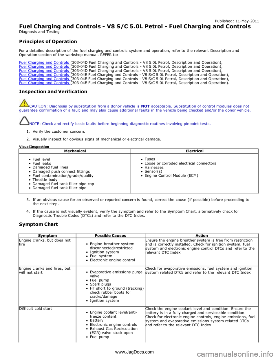
Visual Inspection
Mechanical Electrical
Fuel level
Fuel leaks
Damaged fuel lines
Damaged push connect fittings
Fuel contamination/grade/quality
Throttle body
Damaged fuel tank filler pipe cap
Damaged fuel tank filler pipe
Fuses
Loose or corroded electrical connectors
Harnesses
Sensor(s)
Engine Control Module (ECM)
3. If an obvious cause for an observed or reported concern is found, correct the cause (if possible) before proceeding to
the next step.
4. If the cause is not visually evident, verify the symptom and refer to the Symptom Chart, alternatively check for
Diagnostic Trouble Codes (DTCs) and refer to the DTC Index.
Symptom Chart
Symptom Possible Causes Action Engine cranks, but does not
fire
Engine breather system
disconnected/restricted
Ignition system
Fuel system
Electronic engine control Ensure the engine breather system is free from restriction
and is correctly installed. Check for ignition system, fuel
system and electronic engine control DTCs and refer to the
relevant DTC Index Engine cranks and fires, but
will not start
Evaporative emissions purge
valve
Fuel pump
Spark plugs
HT short to ground (tracking)
check rubber boots for
cracks/damage
Ignition system Check for evaporative emissions, fuel system and ignition
system related DTCs and refer to the relevant DTC Index Difficult cold start
Engine coolant level/anti-
freeze content
Battery
Electronic engine controls
Exhaust Gas Recirculation
(EGR) valve stuck open
Fuel pump Check the engine coolant level and condition. Ensure the
battery is in a fully charged and serviceable condition.
Check for electronic engine controls, engine emissions, fuel
system and evaporative emissions system related DTCs
and refer to the relevant DTC Index www.JagDocs.com
Page 1188 of 3039
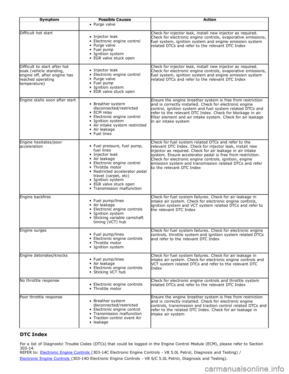
Symptom Possible Causes Action Purge valve
Difficult hot start
Injector leak
Electronic engine control
Purge valve
Fuel pump
Ignition system
EGR valve stuck open Check for injector leak, install new injector as required.
Check for electronic engine controls, evaporative emissions,
fuel system, ignition system and engine emission system
related DTCs and refer to the relevant DTC Index Difficult to start after hot
soak (vehicle standing,
engine off, after engine has
reached operating
temperature)
Injector leak
Electronic engine control
Purge valve
Fuel pump
Ignition system
EGR valve stuck open Check for injector leak, install new injector as required.
Check for electronic engine controls, evaporative emissions,
fuel system, ignition system and engine emission system
related DTCs and refer to the relevant DTC Index Engine stalls soon after start
Breather system
disconnected/restricted
ECM relay
Electronic engine control
Ignition system
Air intake system restricted
Air leakage
Fuel lines Ensure the engine breather system is free from restriction
and is correctly installed. Check for electronic engine
control, ignition system and fuel system related DTCs and
refer to the relevant DTC Index. Check for blockage in air
filter element and air intake system. Check for air leakage
in air intake system Engine hesitates/poor
acceleration
Fuel pressure, fuel pump,
fuel lines
Injector leak
Air leakage
Electronic engine control
Throttle motor
Restricted accelerator pedal
travel (carpet, etc)
Ignition system
EGR valve stuck open
Transmission malfunction Check for fuel system related DTCs and refer to the
relevant DTC Index. Check for injector leak, install new
injector as required. Check for air leakage in air intake
system. Ensure accelerator pedal is free from restriction.
Check for electronic engine controls, ignition, engine
emission system and transmission related DTCs and refer
to the relevant DTC Index Engine backfires
Fuel pump/lines
Air leakage
Electronic engine controls
Ignition system
Sticking variable camshaft
timing (VCT) hub Check for fuel system failures. Check for air leakage in
intake air system. Check for electronic engine controls,
ignition system and VCT system related DTCs and refer to
the relevant DTC Index Engine surges
Fuel pump/lines
Electronic engine controls
Throttle motor
Ignition system Check for fuel system failures. Check for electronic engine
controls, throttle system and ignition system related DTCs
and refer to the relevant DTC Index Engine detonates/knocks
Fuel pump/lines
Air leakage
Electronic engine controls
Sticking VCT hub Check for fuel system failures. Check for air leakage in
intake air system. Check for electronic engine controls and
VCT system related DTCs and refer to the relevant DTC
Index No throttle response
Electronic engine controls
Throttle motor Check for electronic engine controls and throttle system
related DTCs and refer to the relevant DTC Index Poor throttle response
Breather system
disconnected/restricted
Electronic engine control
Transmission malfunction
Traction control event Air
leakage Ensure the engine breather system is free from restriction
and is correctly installed. Check for electronic engine
controls, transmission and traction control related DTCs and
refer to the related DTC Index. Check for air leakage in
intake air system DTC Index
For a list of Diagnostic Trouble Codes (DTCs) that could be logged in the Engine Control Module (ECM), please refer to Section
303-14.
REFER to: Electronic Engine Controls (303-14C Electronic Engine Controls - V8 5.0L Petrol, Diagnosis and Testing) / Electronic Engine Controls (303-14D Electronic Engine Controls - V8 S/C 5.0L Petrol, Diagnosis and Testing).
Page 1189 of 3039
Published: 11-May-2011
Fuel Charging and Controls - V8 S/C 5.0L Petrol - Fuel Injection Component Cleaning
General Procedures
General Equipment
WARNINGS: Cleaning
Do not carry out any repairs to the fuel system with the engine running. Failure to follow this instruction may result in
personal injury.
Do not smoke or carry lighted tobacco or open flame of any type when working on or near any fuel related components.
Highly flammable vapors are always present and may ignite. Failure to follow these instructions may result in personal injury.
If fuel contacts the eyes, flush the eyes with cold water or eyewash solution and seek immediate medical attention.
Place the vehicle in a well ventilated, quarantined area and arrange ' No Smoking/Petrol Fumes' signs about the vehicle.
Wash hands thoroughly after fuel handling, as prolonged contact may cause irritation. Should irritation develop, seek
medical attention.
Do not carry or operate cellular phones when working on or near any fuel related components. Highly flammable vapors
are always present and may ignite. Failure to follow these instructions may result in personal injury.
CAUTIONS:
Before using the cleaning fluid, protect all electrical components and connectors with lint-free non-flocking material.
Make sure that all parts removed from the vehicle are placed on the lint-free non-flocking material.
Make sure that any protective clothing worn is clean and made from lint-free non-flocking material.
Make sure that clean non-plated tools are used. Clean tools using a new brush that will not lose its bristles, prior to
starting work on the vehicle.
Use a steel topped workbench and cover it with clean, lint-free non-flocking material.
Make sure the workshop area in which the vehicle is being worked on is as clean and as dust free as possible. Foreign
matter from work on clutches, brakes or from machining or welding operations can contaminate the fuel system and may result
in later malfunction.
1. Using a new brush that will not lose its bristles, brush the components
being removed and the surrounding area.
2. Using a pneumatic vacuum gun, remove all traces of foreign material.
General Equipment: Pneumatic vacuum gun Pneumatic vacuum gun
Page 1198 of 3039

6. CAUTIONS:
Make sure that the area around the open fuel injector ports are clean
and free of foreign material and lubricant prior to installing the fuel injector.
When Installing the fuel injector(s), make sure that the Teflon seal is
clean and free of foreign material and lubricant.
7. CAUTIONS:
If new fuel injectors are installed, a new injector clamp must be
installed
Make sure that the fuel injector is aligned and installed into the fuel
rail correctly, as noted in the removal step.
Tighten the fuel rail retaining bolts a turn at a time until the correct
torque is achieved.
NOTE: Lubricate the fuel injector O-ring seals with clean engine oil.
Torque: 20 Nm
8. Special Tool(s): 310-200-01, 310-200-02 9. Torque: 20 Nm
Page 1200 of 3039

14.
15. NOTES:
Lubricate
the union
threads with
clean engine
oil.
Do not
tighten at
this stage.
Remove and
discard the
blanking
caps.
Torque:
union 21 Nm bolts 8 Nm
16.
Torque: 21 Nm
17.
Refer to: Air Cleaner Outlet Pipe RH (303-12C Intake Air Distribution and Filtering - V8 5.0L Petrol, Removal and Installation).