Engine JAGUAR XFR 2010 1.G Workshop Manual
[x] Cancel search | Manufacturer: JAGUAR, Model Year: 2010, Model line: XFR, Model: JAGUAR XFR 2010 1.GPages: 3039, PDF Size: 58.49 MB
Page 1106 of 3039

Procedures).
34. Refer to: Cooling System Partial Draining, Filling and Bleeding - V8 S/C 5.0L Petrol (303-03C Engine Cooling - V8 5.0L Petrol/V8 S/C 5.0L Petrol, General Procedures).
35. Refer to: Air Cleaner RH (303-12C Intake Air Distribution and Filtering - V8 5.0L Petrol, Removal and Installation).
36. Refer to: Air Cleaner LH (303-12C Intake Air Distribution and Filtering - V8 5.0L Petrol, Removal and Installation).
37. Refer to: Cowl Vent Screen (501-02 Front End Body Panels, Removal and Installation).
38. Refer to: Battery Disconnect and Connect (414-01 Battery, Mounting and Cables, General Procedures).
www.JagDocs.com
Page 1107 of 3039
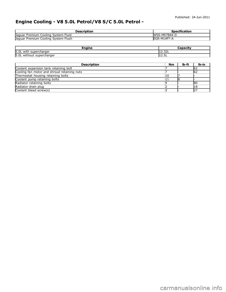
Jaguar Premium Cooling System Fluid WSS-M97B44-D Jaguar Premium Cooling System Flush EGR-M14P7-A
Engine Capacity 5.0L with supercharger 12.32L 5.0L without supercharger 12.5L
Description Nm lb-ft lb-in Coolant expansion tank retaining bolt 7 - 62 Cooling fan motor and shroud retaining nuts 7 - 62 Thermostat housing retaining bolts 10 7 - Coolant pump retaining bolts 11 8 - Radiator retaining bolts 9 - 80 Radiator drain plug 2 - 18 Coolant bleed screw(s) 3 - 27
Page 1108 of 3039
Published: 11-May-2011
Engine Cooling - V8 5.0L Petrol/V8 S/C 5.0L Petrol - Engine Cooling - Component Location
Description and Operation
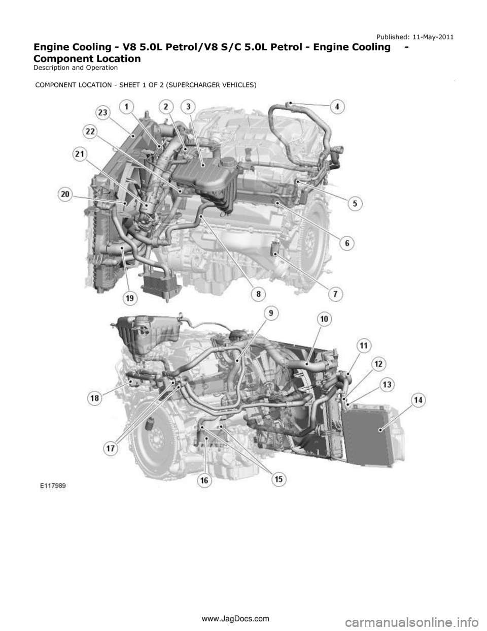
www.JagDocs.comCOMPONENTLOCATION-SHEET1OF2(SUPERCHARGERVEHICLES)
Page 1109 of 3039

1 Engine vent hose 2 Throttle 3 Coolant expansion tank 4 Bleed point 5 Throttle body heater hose 6 Engine oil cooler 7 Engine block heater (110 V version shown) or drain plug 8 Coolant supply/expansion hose 9 Outlet tube 10 Radiator upper hose 11 Supercharger cooling system connecting hose 12 Auxiliary radiator supply hose 13 Auxiliary radiator return hose 14 Auxiliary radiator 15 Transmission fluid cooler supply and return hoses 16 Transmission fluid cooler 17 Heater core supply and return hoses 18 Heater manifold 19 Radiator lower hose 20 Cooling fan 21 Thermostat 22 Coolant pump 23 Radiator
Page 1110 of 3039

1 Engine block heater Comments:
110 V ac version shown, 240 V ac version similar. 2 Harness 3 Connector COMPONENT LOCATION - SHEET 2 OF 2
Page 1111 of 3039

Published: 11-May-2011
Engine Cooling - V8 5.0L Petrol/V8 S/C 5.0L Petrol - Engine Cooling - Overview
Description and Operation
OVERVIEW
The engine cooling system maintains the engine within an optimum temperature range under changing ambient and engine
operating conditions. The system is a pressurized expansion tank system with continuous bleeds to separate air from the
coolant and prevent the formation of air locks. The engine cooling system also provides:
Heating for:
- The passenger compartment. For additional information, refer to 412-01 Climate Control.
- The throttle body.
Cooling for:
- The engine oil cooler. For additional information, refer to 303-01F Engine - 5.0L, Vehicles With: Supercharger or
303-01E Engine - 5.0L, Vehicles Without: Supercharger.
- The transmission fluid cooler. For additional information, refer to 307-02B Transmission/Transaxle Cooling -
5.0L/3.0L Diesel.
The primary components of the engine cooling system are the:
Coolant pump.
Thermostat.
Radiator.
Auxiliary radiator (SC (supercharger) vehicles only).
Cooling fan.
Expansion tank.
Engine oil cooler.
Outlet tube and heater manifold.
Connecting hoses and pipes.
Page 1112 of 3039
Published: 11-May-2011
Engine Cooling - V8 5.0L Petrol/V8 S/C 5.0L Petrol - Engine Cooling - System
Operation and Component Description
Description and Operation
Control Diagram
NOTE: A = Hardwired
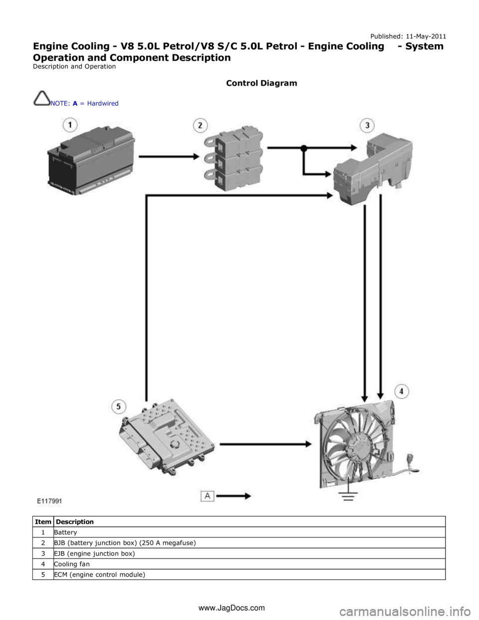
Item Description 1 Battery 2 BJB (battery junction box) (250 A megafuse) 3 EJB (engine junction box) 4 Cooling fan 5 ECM (engine control module) www.JagDocs.com
Page 1113 of 3039
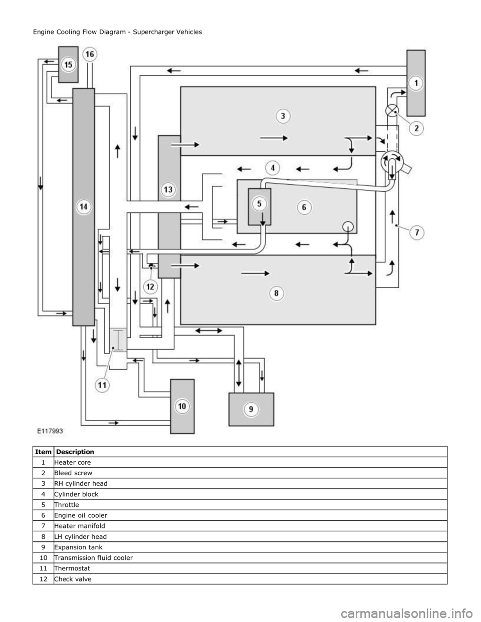
1 Heater core 2 Bleed screw 3 RH cylinder head 4 Cylinder block 5 Throttle 6 Engine oil cooler 7 Heater manifold 8 LH cylinder head 9 Expansion tank 10 Transmission fluid cooler 11 Thermostat 12 Check valve
Page 1114 of 3039
14 Radiator 15 Auxiliary radiator 16 Connection with supercharger cooling system
System Operation
When the engine is running, the coolant is circulated around the engine cooling system by the coolant pump. From the coolant
pump, coolant flows through the cylinder heads and the engine oil cooler into the cylinder block and the heater manifold.
In the cylinder block, the coolant flows forwards to the outlet tube. When the coolant is cold, the thermostat is closed and the
coolant flows direct from the outlet tube back to the coolant pump. Once the coolant reaches operating temperature the
thermostat begins to open, to control system temperature, and coolant flows from the outlet tube to the coolant pump via the
radiator and, on SC (supercharger) vehicles, the auxiliary radiator. When the thermostat is open, the coolant flow through the
radiator(s) also generates a coolant flow through the transmission fluid cooler.
From the heater manifold the coolant flows through the electronic throttle and the heater core, in parallel circuits that are
unaffected by the position of the thermostat. From the electronic throttle, the coolant merges with bleed coolant from the
coolant pump and the outlet tube and flows to the expansion tank. From the heater core, the coolant flows back to the inlet of
the coolant pump.
Expansion and contraction of the coolant is accommodated by an air space in the expansion tank and the compliance of the
flexible hoses.
If the coolant level in the expansion tank decreases below a predetermined value, the level sensor connects a ground to the
instrument cluster, which activates the appropriate warning. For additional information, refer to 413-01 Instrument Cluster.
The cooling fan is operated by a fan control module integrated into the cooling fan motor. The fan control module regulates the
voltage, and thus speed, of the cooling fan motor in response to a PWM (pulse width modulation) signal from the ECM (engine
control module).
The cooling fan receives a battery feed and an ignition feed from the EJB (engine junction box). The ignition feed is supplied
from the main relay in the EJB, which is controlled by the ECM.
The ECM calculates the required fan speed from the engine temperature, A/C (air conditioning) system pressure and transmission fluid temperature. Under hot operating conditions, the fan may continue to operate for 4 minutes after the engine
has been switched off.
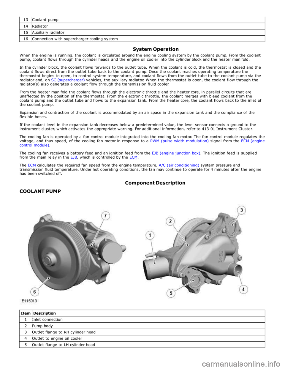
COOLANT PUMP Component Description
Item Description 1 Inlet connection 2 Pump body 3 Outlet flange to RH cylinder head 4 Outlet to engine oil cooler 5 Outlet flange to LH cylinder head
Page 1115 of 3039
7 Bleed pipe connection (containing check valve) The body of the coolant pump contains an impeller attached to a shaft supported in a bearing assembly. The impeller is driven
by a pulley, pressed on to the front of the shaft, which is driven by the accessory drive belt. For additional information, refer to
303-05E Accessory Drive - 5.0L, Vehicles Without: Supercharger or 303-05F - 5.0L, Vehicles With: Supercharger.
Two coolant outlet flanges attach the coolant pump to the front of the cylinder heads. A pipe connects a further coolant outlet
to a pipe from the engine oil cooler. A bleed connector is installed in the front of the coolant pump, adjacent to the coolant
inlet connection from the thermostat. A check valve is incorporated into the bleed connection.
THERMOSTAT
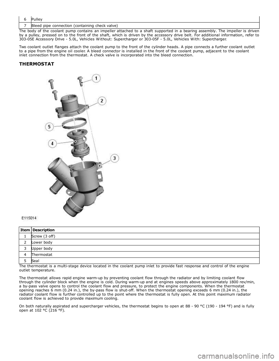
Item Description 1 Screw (3 off) 2 Lower body 3 Upper body 4 Thermostat 5 Seal The thermostat is a multi-stage device located in the coolant pump inlet to provide fast response and control of the engine
outlet temperature.
The thermostat allows rapid engine warm-up by preventing coolant flow through the radiator and by limiting coolant flow
through the cylinder block when the engine is cold. During warm-up and at engines speeds above approximately 1800 rev/min,
a by-pass valve opens to control the coolant flow and pressure, to protect the engine components. When the thermostat
opening reaches 6 mm (0.24 in.), the by-pass flow is shut-off. When the thermostat opening exceeds 6 mm (0.24 in.), the
radiator coolant flow is further controlled up to the point where the thermostat is fully open. At this point maximum radiator
coolant flow is achieved to provide maximum cooling.
On both naturally aspirated and supercharger vehicles, the thermostat begins to open at 88 - 90 °C (190 - 194 °F) and is fully
open at 102 °C (216 °F).