JAGUAR XFR 2010 1.G Owner's Manual
XFR 2010 1.G
JAGUAR
JAGUAR
https://www.carmanualsonline.info/img/21/7642/w960_7642-0.png
JAGUAR XFR 2010 1.G Owner's Manual
Page 868 of 3039
cooling jets and the timing chain lubrication jets.
The oil returns to the oil pan under gravity. Large drain holes through the cylinder heads and cylinder block ensure the rapid
return of the oil to the sump pan. System replenishment is through the oil filler cap on the LH cylinder head cover.
An oil evacuation tube is installed to allow oil to be drawn from the sump pan. The upper end of the oil evacuation tube is
located under the oil filler cap.
An oil drain plug is installed in the RH side of the sump pan.
Oil Pump Nominal Operating Pressures
Engine Speed, rev/min Temperature, °C (°F) Pressure, bar (lbf/in2
) Idle 20 (68) 2.0 (29.0) 1500 20 (68) 6.0 (87.0) 3000 40 (104) 6.2 (90.0) 3000 110 (230) 5.0 (72.5) 3000 130 (266) 4.0 (58.0) Oil Level Monitoring
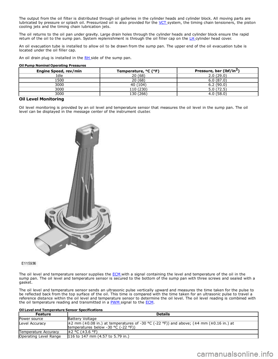
Oil level monitoring is provided by an oil level and temperature sensor that measures the oil level in the sump pan. The oil
level can be displayed in the message center of the instrument cluster.
The oil level and temperature sensor supplies the ECM with a signal containing the level and temperature of the oil in the sump pan. The oil level and temperature sensor is secured to the bottom of the sump pan with three screws and sealed with a
gasket.
The oil level and temperature sensor sends an ultrasonic pulse vertically upward and measures the time taken for the pulse to
be reflected back from the top surface of the oil. This time is compared with the time taken for an ultrasonic pulse to travel a
reference distance within the oil level and temperature sensor to determine the oil level. The oil level reading is combined with
the oil temperature reading and transmitted in a PWM signal to the ECM.
Oil Level and Temperature Sensor Specifications
Feature Details Power source Battery Voltage Level Accuracy ±2 mm (±0.08 in.) at temperatures of -30 °C (-22 °F)) and above; (±4 mm (±0.16 in.) at
temperatures below -30 °C (-22 °F)) Temperature Accuracy ±2 °C (±3.6 °F) Operating Level Range 116 to 147 mm (4.57 to 5.79 in.)
Page 934 of 3039
Engine - V8 S/C 5.0L Petrol - Cylinder Head LH
Removal and Installation
Removal
NOTE: Removal steps in this procedure may contain installation details. Published: 18-May-2012
1. Refer to: Battery Disconnect and Connect (414-01 Battery, Mounting and Cables, General Procedures).
2. WARNING: Make sure to support the vehicle with axle stands.
Raise and support the vehicle.
3. Refer to: Camshaft LH (303-01D Engine - V8 S/C 5.0L Petrol, Removal and Installation).
4. Refer to: Exhaust Manifold LH (303-01C Engine - V8 5.0L Petrol, Removal and Installation).
5.
6.
Page 938 of 3039
17.
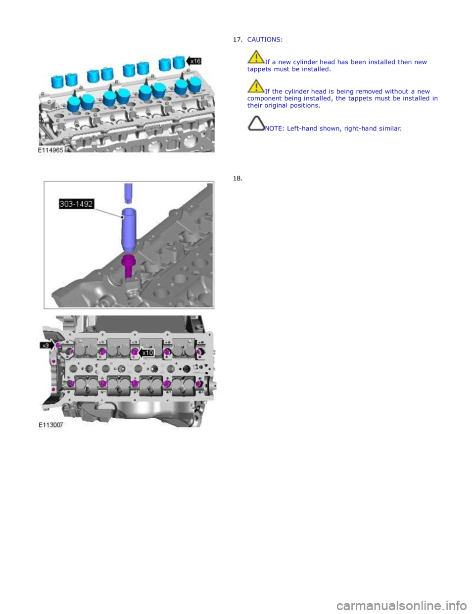
18. CAUTIONS:
If a new cylinder head has been installed then new
tappets must be installed.
If the cylinder head is being removed without a new
component being installed, the tappets must be installed in
their original positions.
NOTE: Left-hand shown, right-hand similar.
Page 939 of 3039
Installation 19.
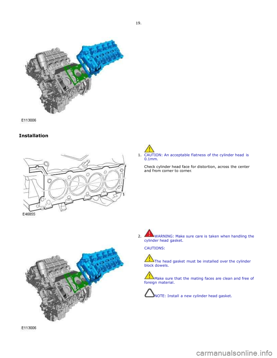
1. CAUTION: An acceptable flatness of the cylinder head is
0.1mm.
Check cylinder head face for distortion, across the center
and from corner to corner.
2. WARNING: Make sure care is taken when handling the
cylinder head gasket.
CAUTIONS:
The head gasket must be installed over the cylinder
block dowels.
Make sure that the mating faces are clean and free of
foreign material.
NOTE: Install a new cylinder head gasket.
Page 940 of 3039
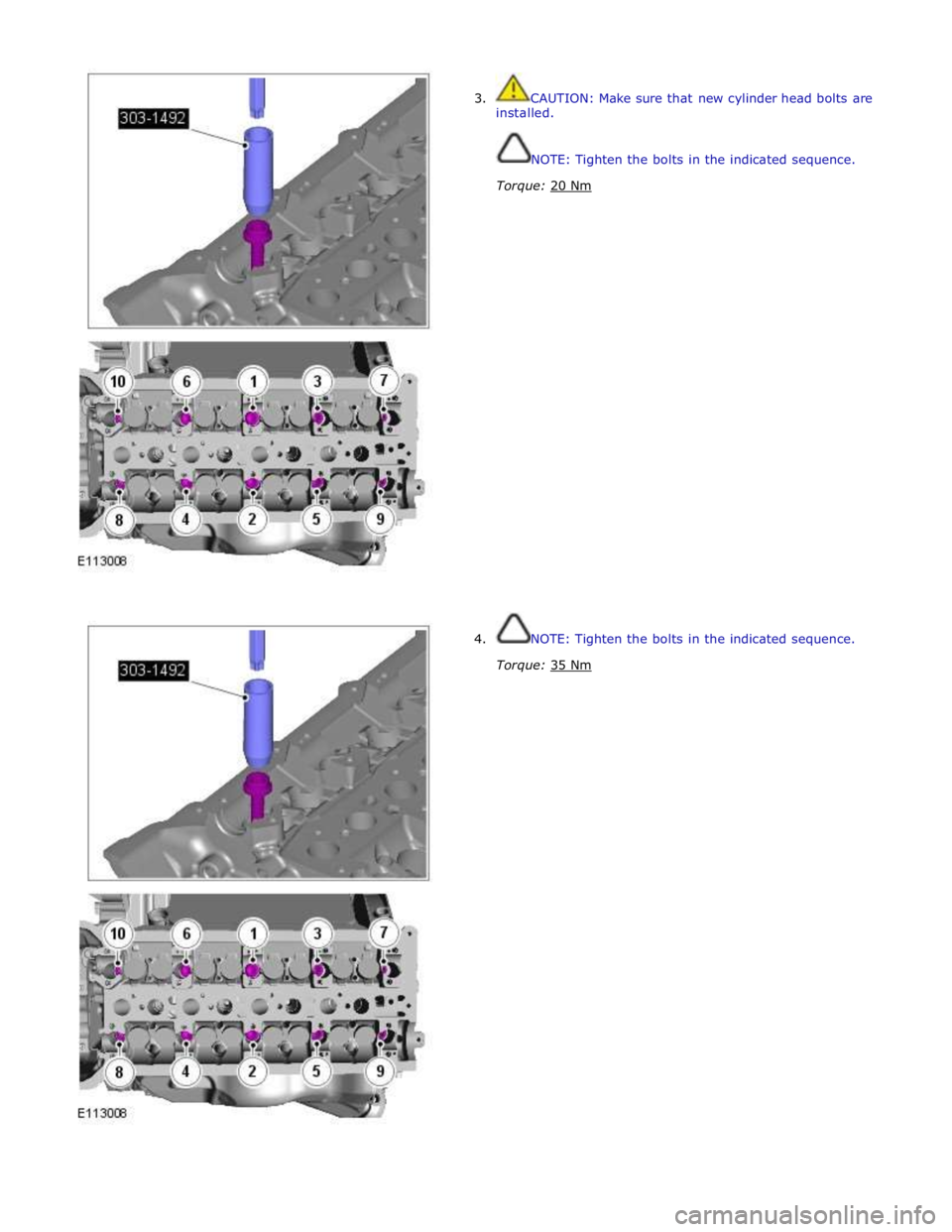
3. CAUTION: Make sure that new cylinder head bolts are
installed.
NOTE: Tighten the bolts in the indicated sequence.
Torque: 20 Nm
4. NOTE: Tighten the bolts in the indicated sequence.
Torque: 35 Nm
Page 942 of 3039
7.
8.
9.
10. Torque: 25 Nm
NOTE: Tighten the bolts in the indicated sequence.
Torque: 12 Nm
CAUTIONS:
If a new cylinder head has been installed then new
tappets must be installed.
If the cylinder head is being removed without a new
component being installed, the tappets must be installed in
their original positions.
Lubricate the valve tappets with clean engine oil.
Torque: 10 Nm
Page 947 of 3039
Engine - V8 S/C 5.0L Petrol - Cylinder Head RH
Removal and Installation
Removal
NOTE: Removal steps in this procedure may contain installation details. Published: 11-May-2011
1. Refer to: Battery Disconnect and Connect (414-01 Battery, Mounting and Cables, General Procedures).
2. Raise and support the vehicle.
3. Refer to: Supercharger (303-12D Intake Air Distribution and Filtering - V8 S/C 5.0L Petrol, Removal and Installation).
4. Refer to: Camshaft RH (303-01D Engine - V8 S/C 5.0L Petrol, Removal and Installation).
5. Refer to: Exhaust Manifold (303-01A, Removal and Installation).
6.
Page 952 of 3039
18.
19.
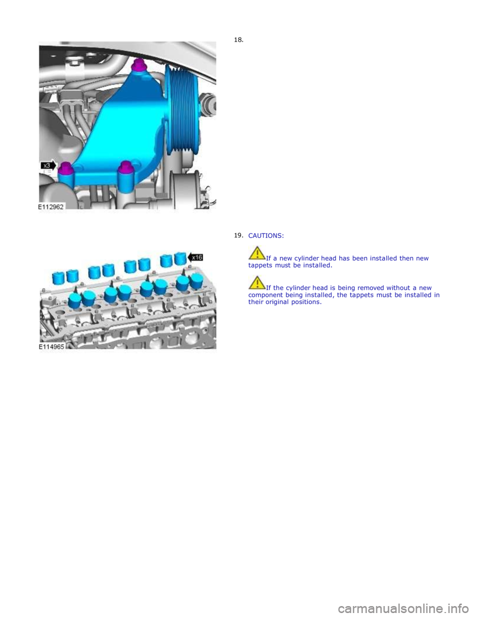
CAUTIONS:
If a new cylinder head has been installed then new
tappets must be installed.
If the cylinder head is being removed without a new
component being installed, the tappets must be installed in
their original positions.
Page 954 of 3039
Installation
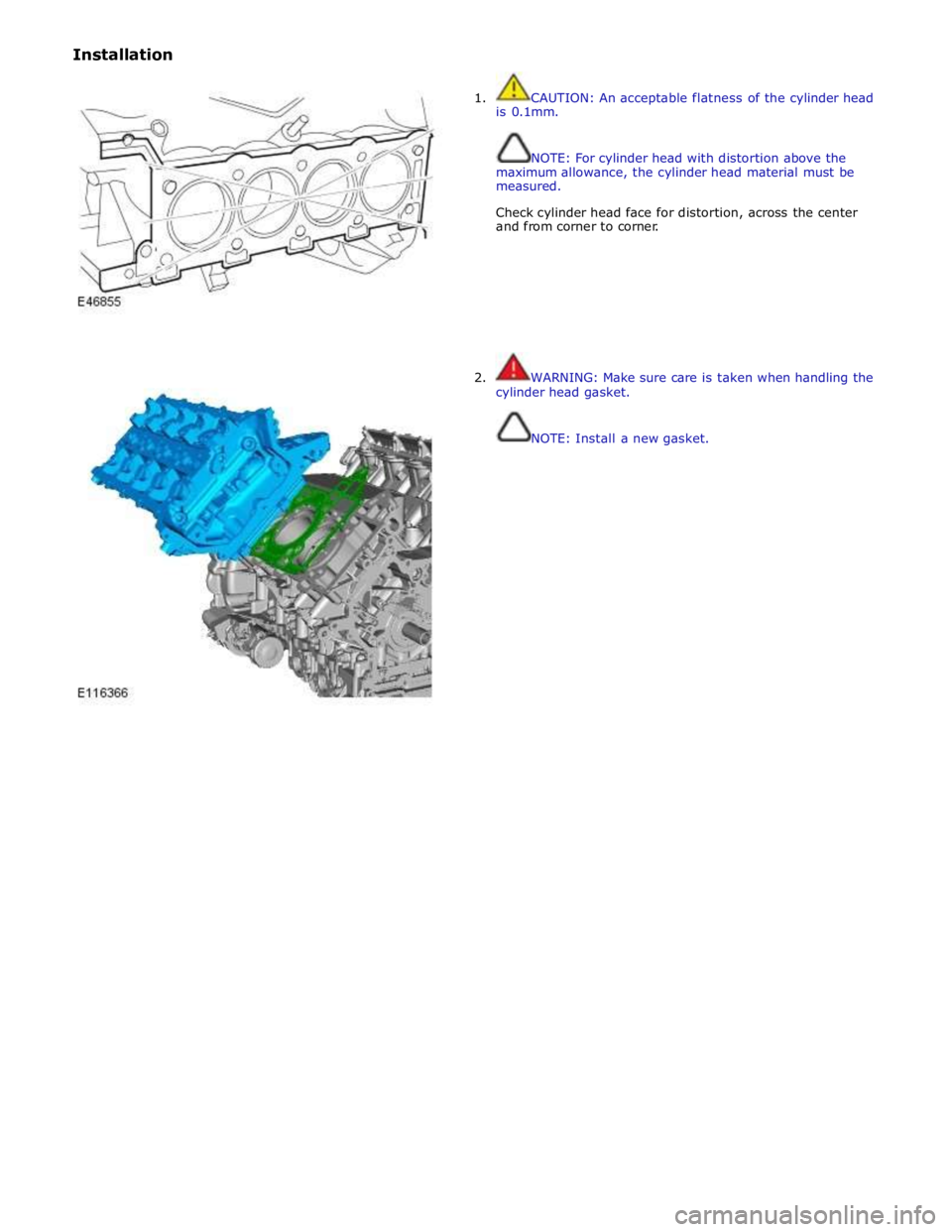
1. CAUTION: An acceptable flatness of the cylinder head
is 0.1mm.
NOTE: For cylinder head with distortion above the
maximum allowance, the cylinder head material must be
measured.
Check cylinder head face for distortion, across the center
and from corner to corner.
2. WARNING: Make sure care is taken when handling the
cylinder head gasket.
NOTE: Install a new gasket.
Page 955 of 3039
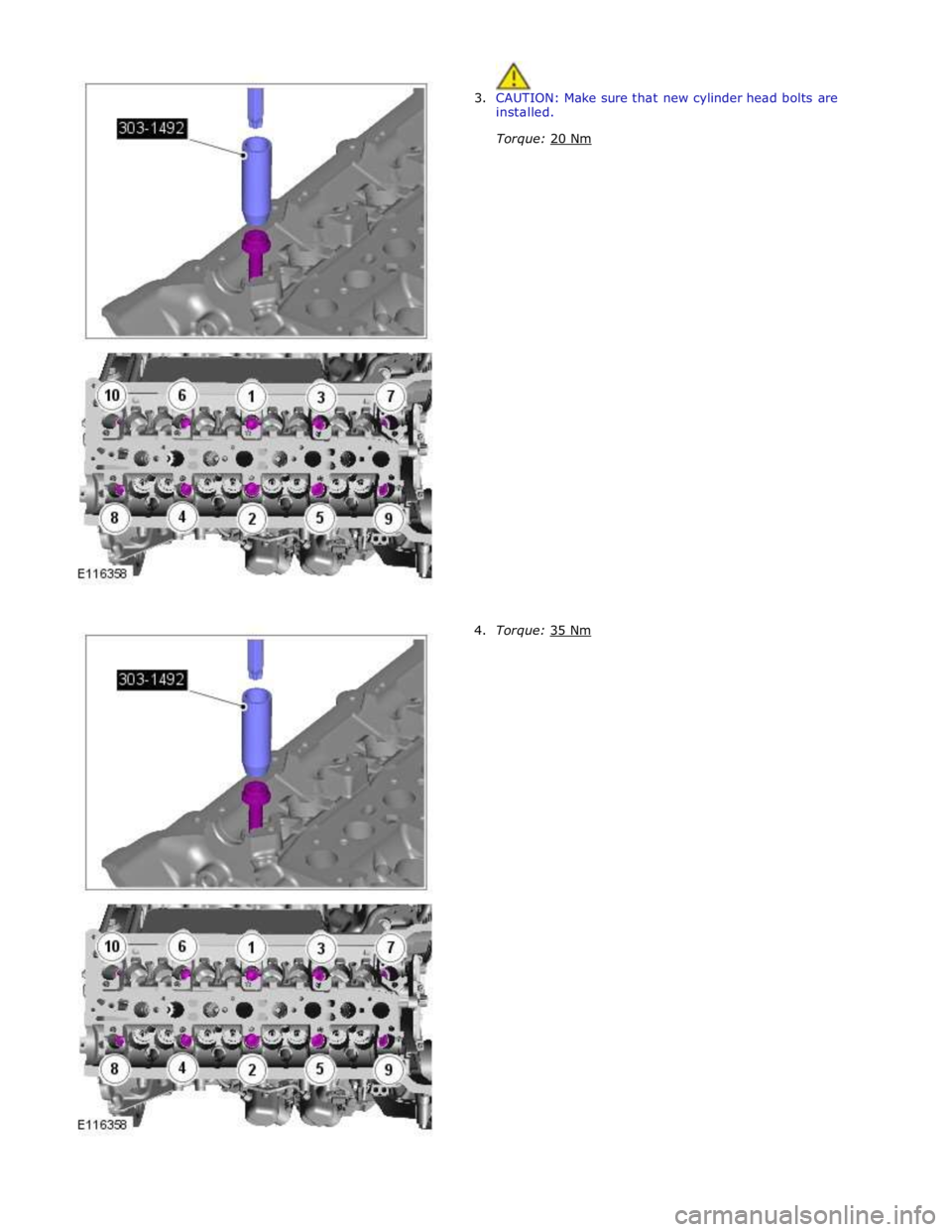
3. CAUTION: Make sure that new cylinder head bolts are
installed.
Torque: 20 Nm
4. Torque: 35 Nm


