Cylinder head JAGUAR XFR 2010 1.G User Guide
[x] Cancel search | Manufacturer: JAGUAR, Model Year: 2010, Model line: XFR, Model: JAGUAR XFR 2010 1.GPages: 3039, PDF Size: 58.49 MB
Page 838 of 3039

Prior to having the cylinder head machined, prior approval is
required by Jaguar or Land Rover engineering.
If the cylinder head requires machining, this must be carried out by
a local engineering company.
If the cylinder head exceeds the maximum value (0.2mm), the cylinder
head must be machined.
Page 844 of 3039
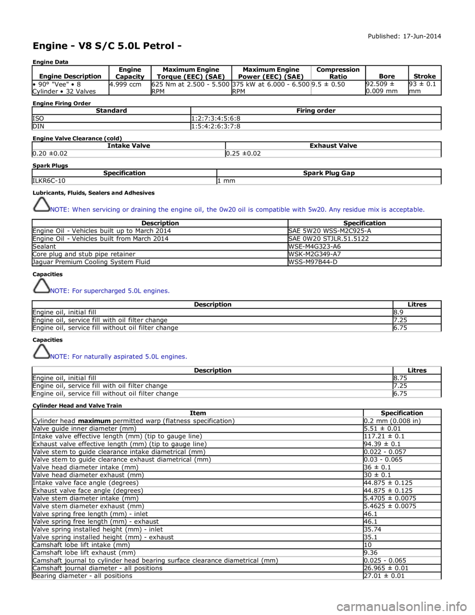
Engine - V8 S/C 5.0L Petrol -
Engine Data Published: 17-Jun-2014
Engine Description Engine Capacity Maximum Engine Torque (EEC) (SAE) Maximum Engine
Power (EEC) (SAE) Compression
Ratio
Bore
Stroke • 90° "Vee" • 8 Cylinder • 32 Valves 4.999 ccm
625 Nm at 2.500 - 5.500
RPM 375 kW at 6.000 - 6.500
RPM 9.5 ± 0.50 92.509 ±
0.009 mm 93 ± 0.1
mm Engine Firing Order
Standard Firing order ISO 1:2:7:3:4:5:6:8 DIN 1:5:4:2:6:3:7:8 Engine Valve Clearance (cold)
Intake Valve Exhaust Valve 0.20 ±0.02 0.25 ±0.02 Spark Plugs
Specification Spark Plug Gap ILKR6C-10 1 mm Lubricants, Fluids, Sealers and Adhesives
NOTE: When servicing or draining the engine oil, the 0w20 oil is compatible with 5w20. Any residue mix is acceptable.
Description Specification Engine Oil - Vehicles built up to March 2014 SAE 5W20 WSS-M2C925-A Engine Oil - Vehicles built from March 2014 SAE 0W20 STJLR.51.5122 Sealant WSE-M4G323-A6 Core plug and stub pipe retainer WSK-M2G349-A7 Jaguar Premium Cooling System Fluid WSS-M97B44-D Capacities
NOTE: For supercharged 5.0L engines.
Description Litres Engine oil, initial fill 8.9 Engine oil, service fill with oil filter change 7.25 Engine oil, service fill without oil filter change 6.75 Capacities
NOTE: For naturally aspirated 5.0L engines.
Description Litres Engine oil, initial fill 8.75 Engine oil, service fill with oil filter change 7.25 Engine oil, service fill without oil filter change 6.75 Cylinder Head and Valve Train
Item Specification Cylinder head maximum permitted warp (flatness specification) 0.2 mm (0.008 in) Valve guide inner diameter (mm) 5.51 ± 0.01 Intake valve effective length (mm) (tip to gauge line) 117.21 ± 0.1 Exhaust valve effective length (mm) (tip to gauge line) 94.39 ± 0.1 Valve stem to guide clearance intake diametrical (mm) 0.022 - 0.057 Valve stem to guide clearance exhaust diametrical (mm) 0.03 - 0.065 Valve head diameter intake (mm) 36 ± 0.1 Valve head diameter exhaust (mm) 30 ± 0.1 Intake valve face angle (degrees) 44.875 ± 0.125 Exhaust valve face angle (degrees) 44.875 ± 0.125 Valve stem diameter intake (mm) 5.4705 ± 0.0075 Valve stem diameter exhaust (mm) 5.4625 ± 0.0075 Valve spring free length (mm) - inlet 46.1 Valve spring free length (mm) - exhaust 46.1 Valve spring installed height (mm) - inlet 35.74 Valve spring installed height (mm) - exhaust 35.1 Camshaft lobe lift intake (mm) 10 Camshaft lobe lift exhaust (mm) 9.36 Camshaft journal to cylinder head bearing surface clearance diametrical (mm) 0.025 - 0.065 Camshaft journal diameter - all positions 26.965 ± 0.01 Bearing diameter - all positions 27.01 ± 0.01
Page 845 of 3039
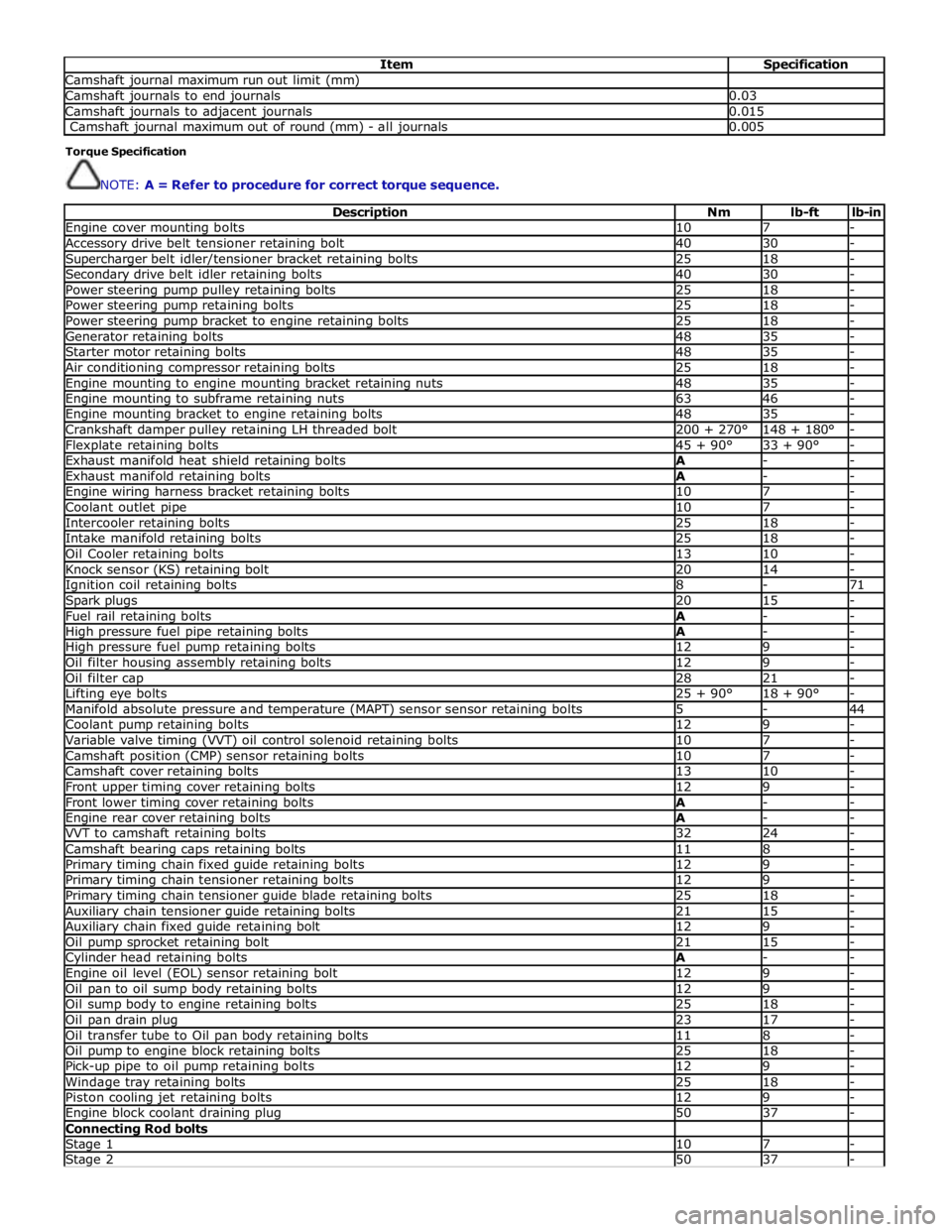
Item Specification Camshaft journal maximum run out limit (mm) Camshaft journals to end journals 0.03 Camshaft journals to adjacent journals 0.015 Camshaft journal maximum out of round (mm) - all journals 0.005 Torque Specification
NOTE: A = Refer to procedure for correct torque sequence.
Description Nm lb-ft lb-in Engine cover mounting bolts 10 7 - Accessory drive belt tensioner retaining bolt 40 30 - Supercharger belt idler/tensioner bracket retaining bolts 25 18 - Secondary drive belt idler retaining bolts 40 30 - Power steering pump pulley retaining bolts 25 18 - Power steering pump retaining bolts 25 18 - Power steering pump bracket to engine retaining bolts 25 18 - Generator retaining bolts 48 35 - Starter motor retaining bolts 48 35 - Air conditioning compressor retaining bolts 25 18 - Engine mounting to engine mounting bracket retaining nuts 48 35 - Engine mounting to subframe retaining nuts 63 46 - Engine mounting bracket to engine retaining bolts 48 35 - Crankshaft damper pulley retaining LH threaded bolt 200 + 270° 148 + 180° - Flexplate retaining bolts 45 + 90° 33 + 90° - Exhaust manifold heat shield retaining bolts A - - Exhaust manifold retaining bolts A - - Engine wiring harness bracket retaining bolts 10 7 - Coolant outlet pipe 10 7 - Intercooler retaining bolts 25 18 - Intake manifold retaining bolts 25 18 - Oil Cooler retaining bolts 13 10 - Knock sensor (KS) retaining bolt 20 14 - Ignition coil retaining bolts 8 - 71 Spark plugs 20 15 - Fuel rail retaining bolts A - - High pressure fuel pipe retaining bolts A - - High pressure fuel pump retaining bolts 12 9 - Oil filter housing assembly retaining bolts 12 9 - Oil filter cap 28 21 - Lifting eye bolts 25 + 90° 18 + 90° - Manifold absolute pressure and temperature (MAPT) sensor sensor retaining bolts 5 - 44 Coolant pump retaining bolts 12 9 - Variable valve timing (VVT) oil control solenoid retaining bolts 10 7 - Camshaft position (CMP) sensor retaining bolts 10 7 - Camshaft cover retaining bolts 13 10 - Front upper timing cover retaining bolts 12 9 - Front lower timing cover retaining bolts A - - Engine rear cover retaining bolts A - - VVT to camshaft retaining bolts 32 24 - Camshaft bearing caps retaining bolts 11 8 - Primary timing chain fixed guide retaining bolts 12 9 - Primary timing chain tensioner retaining bolts 12 9 - Primary timing chain tensioner guide blade retaining bolts 25 18 - Auxiliary chain tensioner guide retaining bolts 21 15 - Auxiliary chain fixed guide retaining bolt 12 9 - Oil pump sprocket retaining bolt 21 15 - Cylinder head retaining bolts A - - Engine oil level (EOL) sensor retaining bolt 12 9 - Oil pan to oil sump body retaining bolts 12 9 - Oil sump body to engine retaining bolts 25 18 - Oil pan drain plug 23 17 - Oil transfer tube to Oil pan body retaining bolts 11 8 - Oil pump to engine block retaining bolts 25 18 - Pick-up pipe to oil pump retaining bolts 12 9 - Windage tray retaining bolts 25 18 - Piston cooling jet retaining bolts 12 9 - Engine block coolant draining plug 50 37 - Connecting Rod bolts Stage 1 10 7 - Stage 2 50 37 -
Page 849 of 3039

1 LH (left hand) cylinder head (bank B) 2 Cylinder block 3 Windage tray 4 Sump body 5 Sump pan 6 RH (right hand) cylinder head (bank A)
Page 850 of 3039
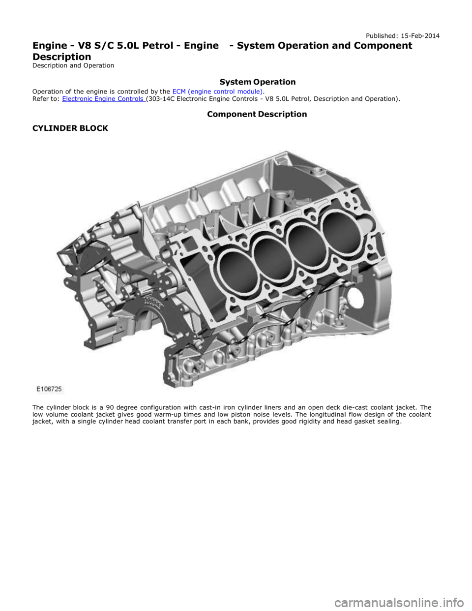
CYLINDER BLOCK Component Description
The cylinder block is a 90 degree configuration with cast-in iron cylinder liners and an open deck die-cast coolant jacket. The
low volume coolant jacket gives good warm-up times and low piston noise levels. The longitudinal flow design of the coolant
jacket, with a single cylinder head coolant transfer port in each bank, provides good rigidity and head gasket sealing.
Page 856 of 3039
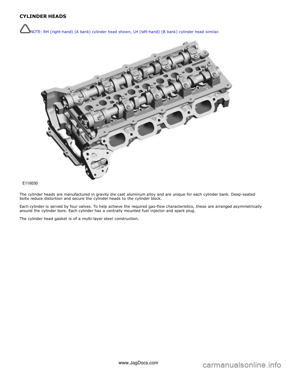
NOTE: RH (right-hand) (A bank) cylinder head shown, LH (left-hand) (B bank) cylinder head similar.
www.JagDocs.com
Page 857 of 3039
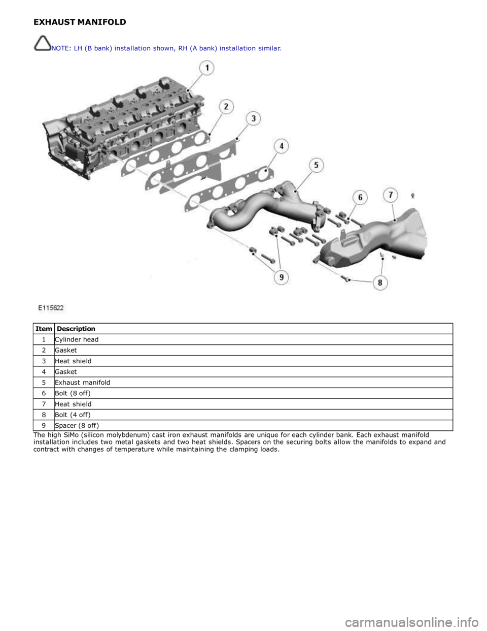
1 Cylinder head 2 Gasket 3 Heat shield 4 Gasket 5 Exhaust manifold 6 Bolt (8 off) 7 Heat shield 8 Bolt (4 off) 9 Spacer (8 off) The high SiMo (silicon molybdenum) cast iron exhaust manifolds are unique for each cylinder bank. Each exhaust manifold
installation includes two metal gaskets and two heat shields. Spacers on the securing bolts allow the manifolds to expand and
contract with changes of temperature while maintaining the clamping loads. NOTE: LH (B bank) installation shown, RH (A bank) installation similar.
Page 858 of 3039
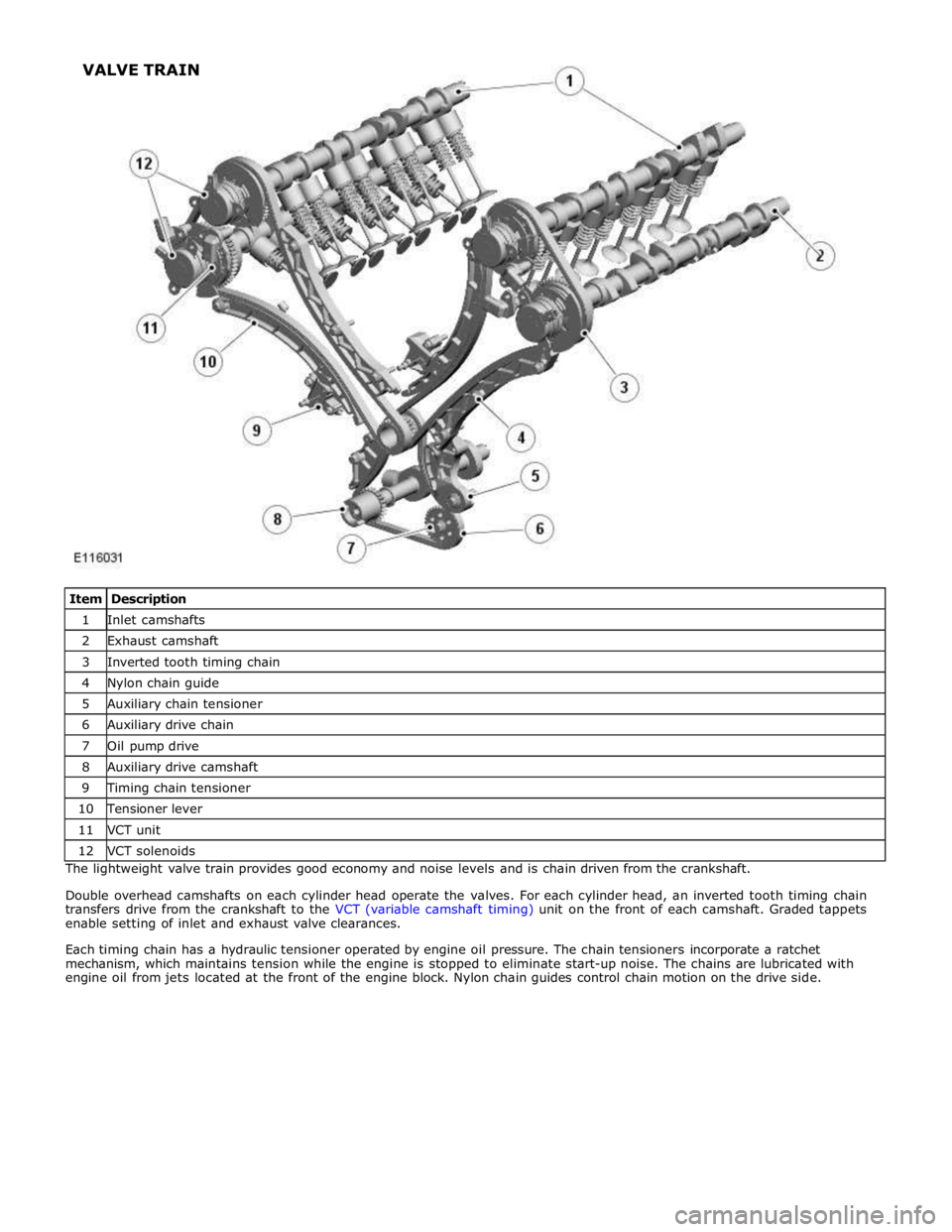
1 Inlet camshafts 2 Exhaust camshaft 3 Inverted tooth timing chain 4 Nylon chain guide 5 Auxiliary chain tensioner 6 Auxiliary drive chain 7 Oil pump drive 8 Auxiliary drive camshaft 9 Timing chain tensioner 10 Tensioner lever 11 VCT unit 12 VCT solenoids The lightweight valve train provides good economy and noise levels and is chain driven from the crankshaft.
Double overhead camshafts on each cylinder head operate the valves. For each cylinder head, an inverted tooth timing chain
transfers drive from the crankshaft to the VCT (variable camshaft timing) unit on the front of each camshaft. Graded tappets
enable setting of inlet and exhaust valve clearances.
Each timing chain has a hydraulic tensioner operated by engine oil pressure. The chain tensioners incorporate a ratchet
mechanism, which maintains tension while the engine is stopped to eliminate start-up noise. The chains are lubricated with
engine oil from jets located at the front of the engine block. Nylon chain guides control chain motion on the drive side. VALVE TRAIN
Page 861 of 3039
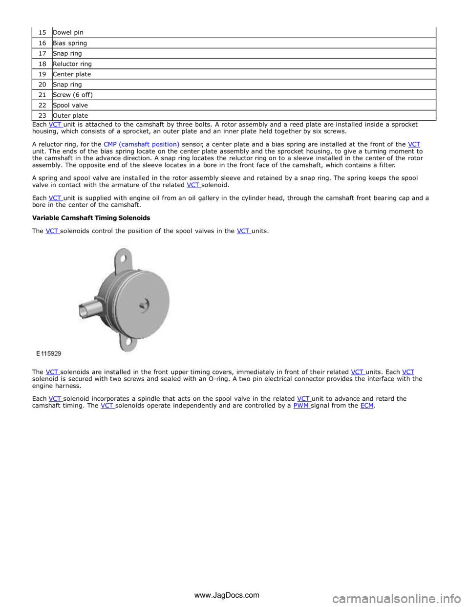
16 Bias spring 17 Snap ring 18 Reluctor ring 19 Center plate 20 Snap ring 21 Screw (6 off) 22 Spool valve 23 Outer plate Each VCT unit is attached to the camshaft by three bolts. A rotor assembly and a reed plate are installed inside a sprocket housing, which consists of a sprocket, an outer plate and an inner plate held together by six screws.
A reluctor ring, for the CMP (camshaft position) sensor, a center plate and a bias spring are installed at the front of the VCT unit. The ends of the bias spring locate on the center plate assembly and the sprocket housing, to give a turning moment to
the camshaft in the advance direction. A snap ring locates the reluctor ring on to a sleeve installed in the center of the rotor
assembly. The opposite end of the sleeve locates in a bore in the front face of the camshaft, which contains a filter.
A spring and spool valve are installed in the rotor assembly sleeve and retained by a snap ring. The spring keeps the spool
valve in contact with the armature of the related VCT solenoid.
Each VCT unit is supplied with engine oil from an oil gallery in the cylinder head, through the camshaft front bearing cap and a bore in the center of the camshaft.
Variable Camshaft Timing Solenoids
The VCT solenoids control the position of the spool valves in the VCT units.
The VCT solenoids are installed in the front upper timing covers, immediately in front of their related VCT units. Each VCT solenoid is secured with two screws and sealed with an O-ring. A two pin electrical connector provides the interface with the
engine harness.
Each VCT solenoid incorporates a spindle that acts on the spool valve in the related VCT unit to advance and retard the camshaft timing. The VCT solenoids operate independently and are controlled by a PWM signal from the ECM. www.JagDocs.com
Page 867 of 3039
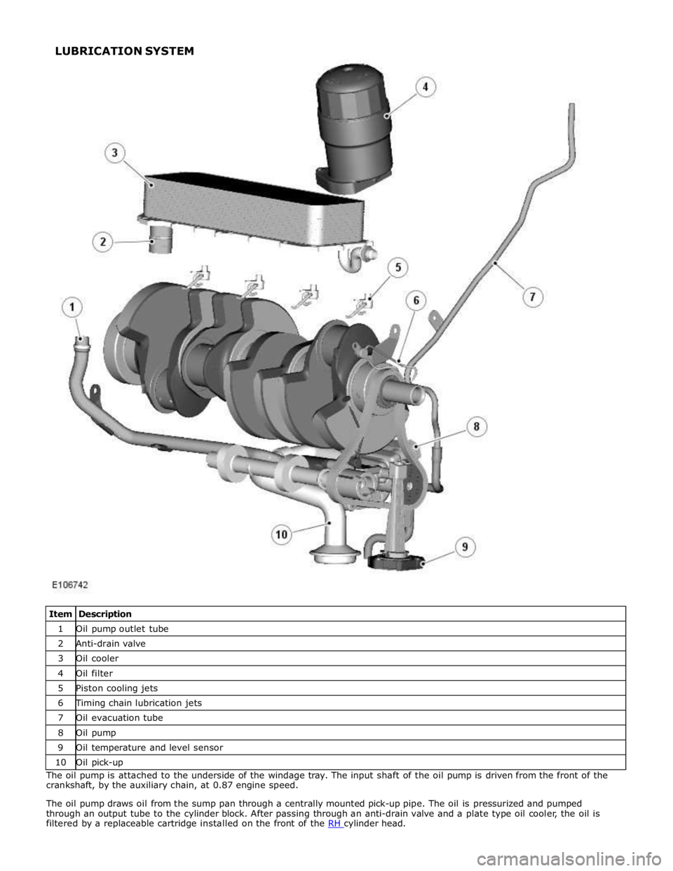
1 Oil pump outlet tube 2 Anti-drain valve 3 Oil cooler 4 Oil filter 5 Piston cooling jets 6 Timing chain lubrication jets 7 Oil evacuation tube 8 Oil pump 9 Oil temperature and level sensor 10 Oil pick-up The oil pump is attached to the underside of the windage tray. The input shaft of the oil pump is driven from the front of the
crankshaft, by the auxiliary chain, at 0.87 engine speed.
The oil pump draws oil from the sump pan through a centrally mounted pick-up pipe. The oil is pressurized and pumped
through an output tube to the cylinder block. After passing through an anti-drain valve and a plate type oil cooler, the oil is
filtered by a replaceable cartridge installed on the front of the RH cylinder head. LUBRICATION SYSTEM