Cylinder head JAGUAR XFR 2010 1.G Repair Manual
[x] Cancel search | Manufacturer: JAGUAR, Model Year: 2010, Model line: XFR, Model: JAGUAR XFR 2010 1.GPages: 3039, PDF Size: 58.49 MB
Page 1322 of 3039

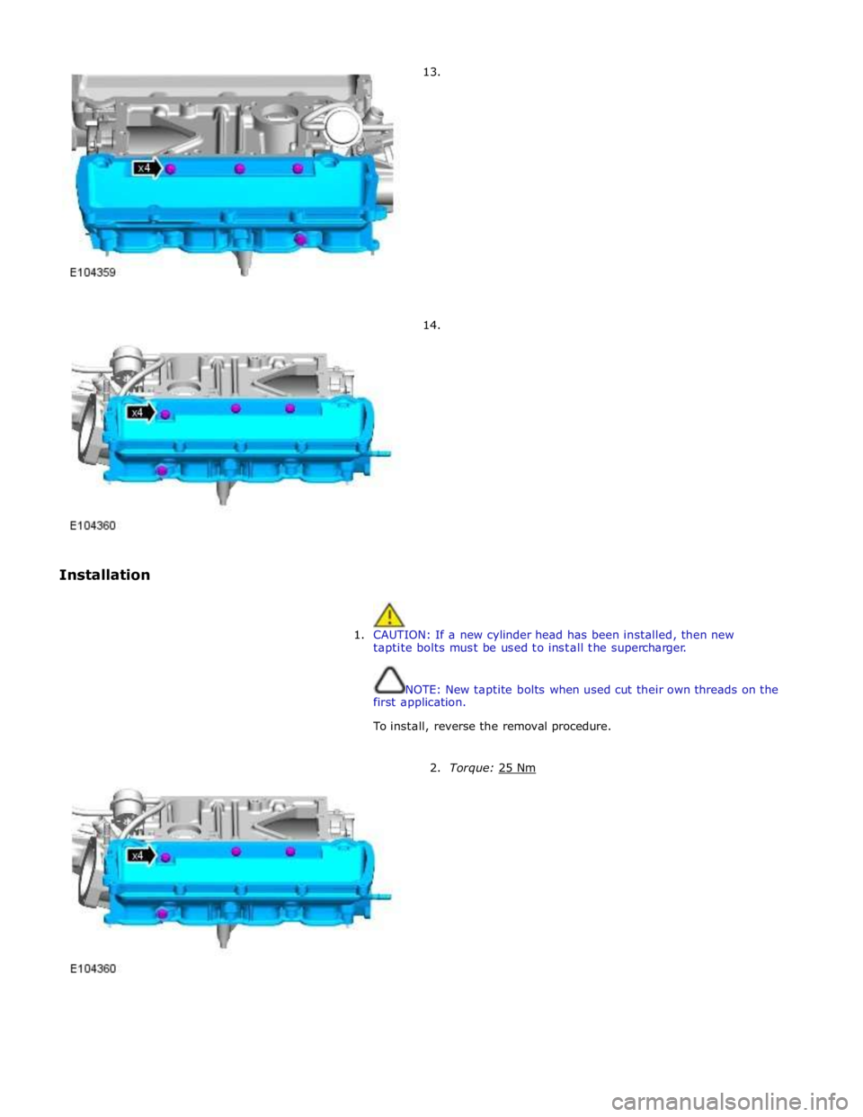
Installation 13.
14.
1. CAUTION: If a new cylinder head has been installed, then new
taptite bolts must be used to install the supercharger.
NOTE: New taptite bolts when used cut their own threads on the
first application.
To install, reverse the removal procedure.
2. Torque: 25 Nm
Page 1323 of 3039

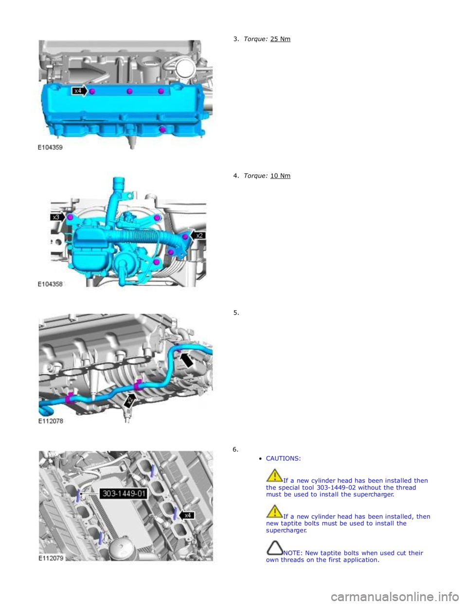
3. Torque: 25 Nm 4. Torque: 10 Nm 5.
6.
CAUTIONS:
If a new cylinder head has been installed then
the special tool 303-1449-02 without the thread
must be used to install the supercharger.
If a new cylinder head has been installed, then
new taptite bolts must be used to install the
supercharger.
NOTE: New taptite bolts when used cut their
own threads on the first application.
Page 1362 of 3039

speed.
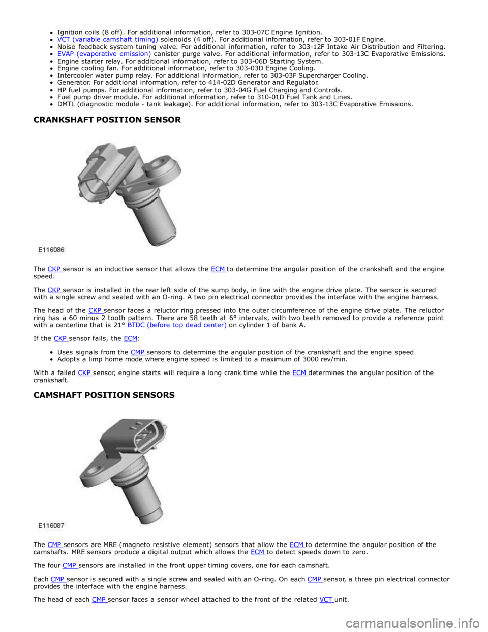
The CKP sensor is installed in the rear left side of the sump body, in line with the engine drive plate. The sensor is secured with a single screw and sealed with an O-ring. A two pin electrical connector provides the interface with the engine harness.
The head of the CKP sensor faces a reluctor ring pressed into the outer circumference of the engine drive plate. The reluctor ring has a 60 minus 2 tooth pattern. There are 58 teeth at 6° intervals, with two teeth removed to provide a reference point
with a centerline that is 21° BTDC (before top dead center) on cylinder 1 of bank A.
If the CKP sensor fails, the ECM:
Uses signals from the CMP sensors to determine the angular position of the crankshaft and the engine speed Adopts a limp home mode where engine speed is limited to a maximum of 3000 rev/min.
With a failed CKP sensor, engine starts will require a long crank time while the ECM determines the angular position of the crankshaft.
CAMSHAFT POSITION SENSORS
The CMP sensors are MRE (magneto resistive element) sensors that allow the ECM to determine the angular position of the camshafts. MRE sensors produce a digital output which allows the ECM to detect speeds down to zero. The four CMP sensors are installed in the front upper timing covers, one for each camshaft.
Each CMP sensor is secured with a single screw and sealed with an O-ring. On each CMP sensor, a three pin electrical connector provides the interface with the engine harness.
The head of each CMP sensor faces a sensor wheel attached to the front of the related VCT unit.
Page 1363 of 3039

Defaults to base mapping for the ignition timing, with no cylinder correction
Disables the VCT system.
ENGINE COOLANT TEMPERATURE SENSORS
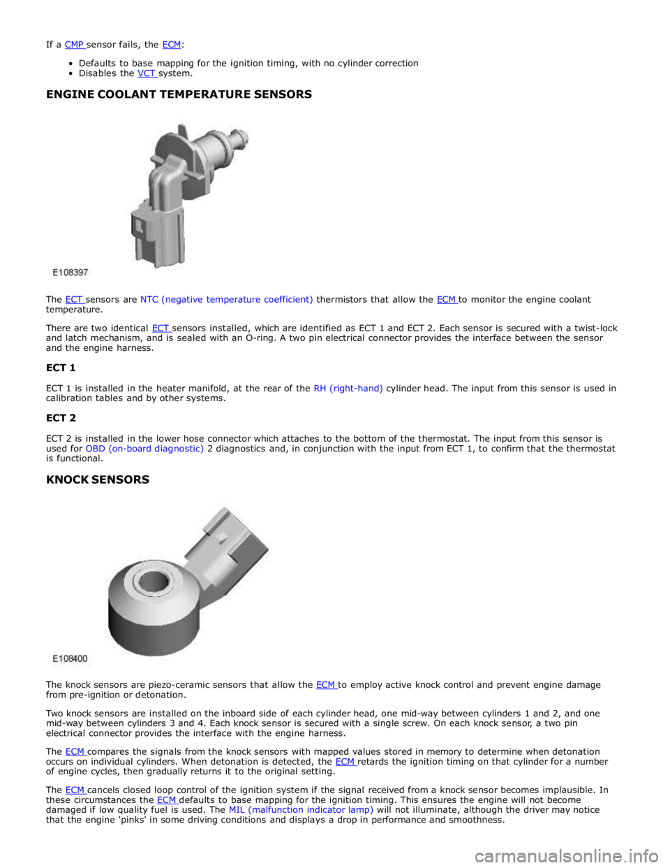
The ECT sensors are NTC (negative temperature coefficient) thermistors that allow the ECM to monitor the engine coolant temperature.
There are two identical ECT sensors installed, which are identified as ECT 1 and ECT 2. Each sensor is secured with a twist-lock and latch mechanism, and is sealed with an O-ring. A two pin electrical connector provides the interface between the sensor
and the engine harness.
ECT 1
ECT 1 is installed in the heater manifold, at the rear of the RH (right-hand) cylinder head. The input from this sensor is used in
calibration tables and by other systems.
ECT 2
ECT 2 is installed in the lower hose connector which attaches to the bottom of the thermostat. The input from this sensor is
used for OBD (on-board diagnostic) 2 diagnostics and, in conjunction with the input from ECT 1, to confirm that the thermostat
is functional.
KNOCK SENSORS
The knock sensors are piezo-ceramic sensors that allow the ECM to employ active knock control and prevent engine damage from pre-ignition or detonation.
Two knock sensors are installed on the inboard side of each cylinder head, one mid-way between cylinders 1 and 2, and one
mid-way between cylinders 3 and 4. Each knock sensor is secured with a single screw. On each knock sensor, a two pin
electrical connector provides the interface with the engine harness.
The ECM compares the signals from the knock sensors with mapped values stored in memory to determine when detonation occurs on individual cylinders. When detonation is detected, the ECM retards the ignition timing on that cylinder for a number of engine cycles, then gradually returns it to the original setting.
The ECM cancels closed loop control of the ignition system if the signal received from a knock sensor becomes implausible. In these circumstances the ECM defaults to base mapping for the ignition timing. This ensures the engine will not become damaged if low quality fuel is used. The MIL (malfunction indicator lamp) will not illuminate, although the driver may notice
that the engine 'pinks' in some driving conditions and displays a drop in performance and smoothness.