Shock JAGUAR XFR 2010 1.G Owner's Manual
[x] Cancel search | Manufacturer: JAGUAR, Model Year: 2010, Model line: XFR, Model: JAGUAR XFR 2010 1.GPages: 3039, PDF Size: 58.49 MB
Page 401 of 3039
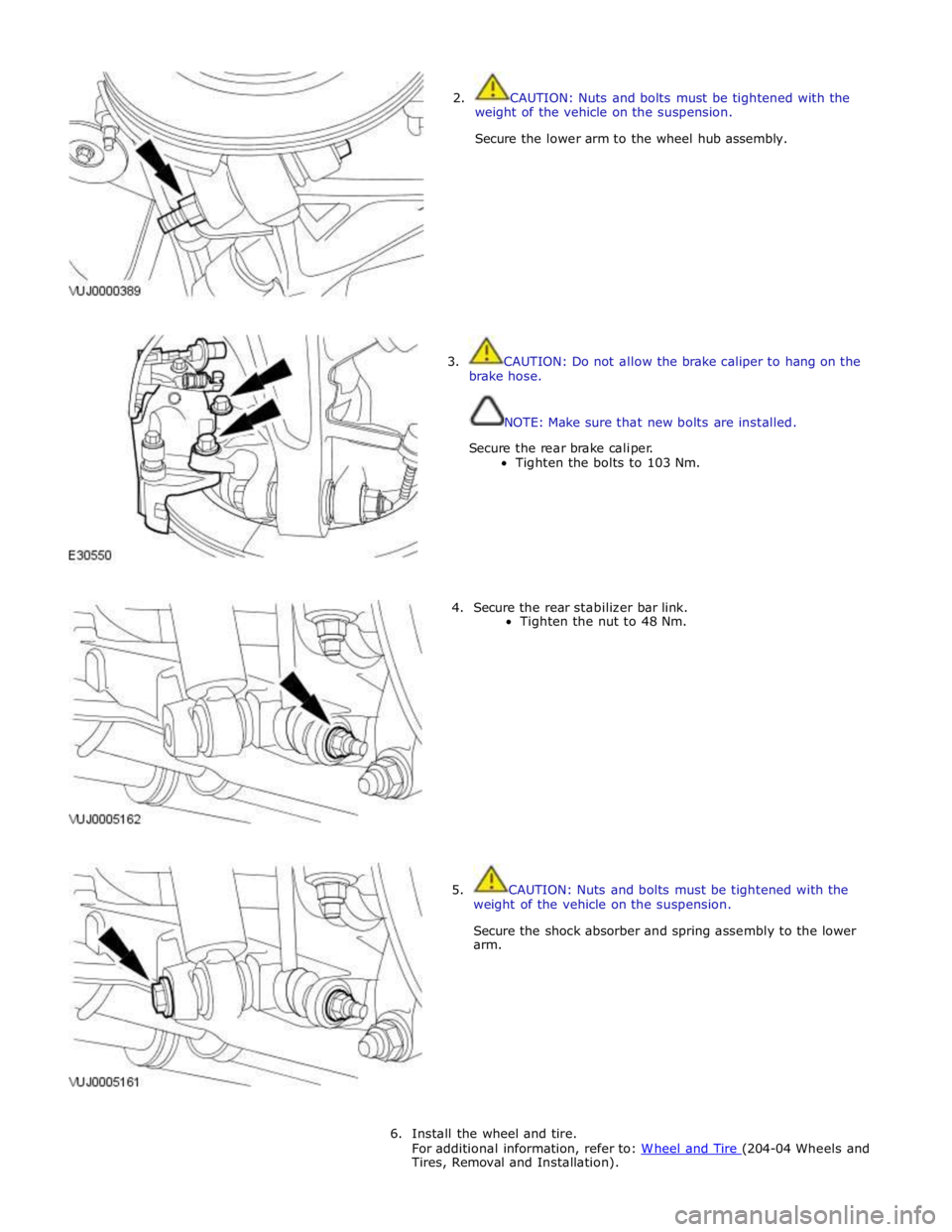
2. CAUTION: Nuts and bolts must be tightened with the
weight of the vehicle on the suspension.
Secure the lower arm to the wheel hub assembly.
3. CAUTION: Do not allow the brake caliper to hang on the
brake hose.
NOTE: Make sure that new bolts are installed.
Secure the rear brake caliper.
Tighten the bolts to 103 Nm.
4. Secure the rear stabilizer bar link.
Tighten the nut to 48 Nm.
5. CAUTION: Nuts and bolts must be tightened with the
weight of the vehicle on the suspension.
Secure the shock absorber and spring assembly to the lower
arm.
6. Install the wheel and tire.
For additional information, refer to: W heel and Tire (204-04 Wheels and Tires, Removal and Installation).
Page 403 of 3039
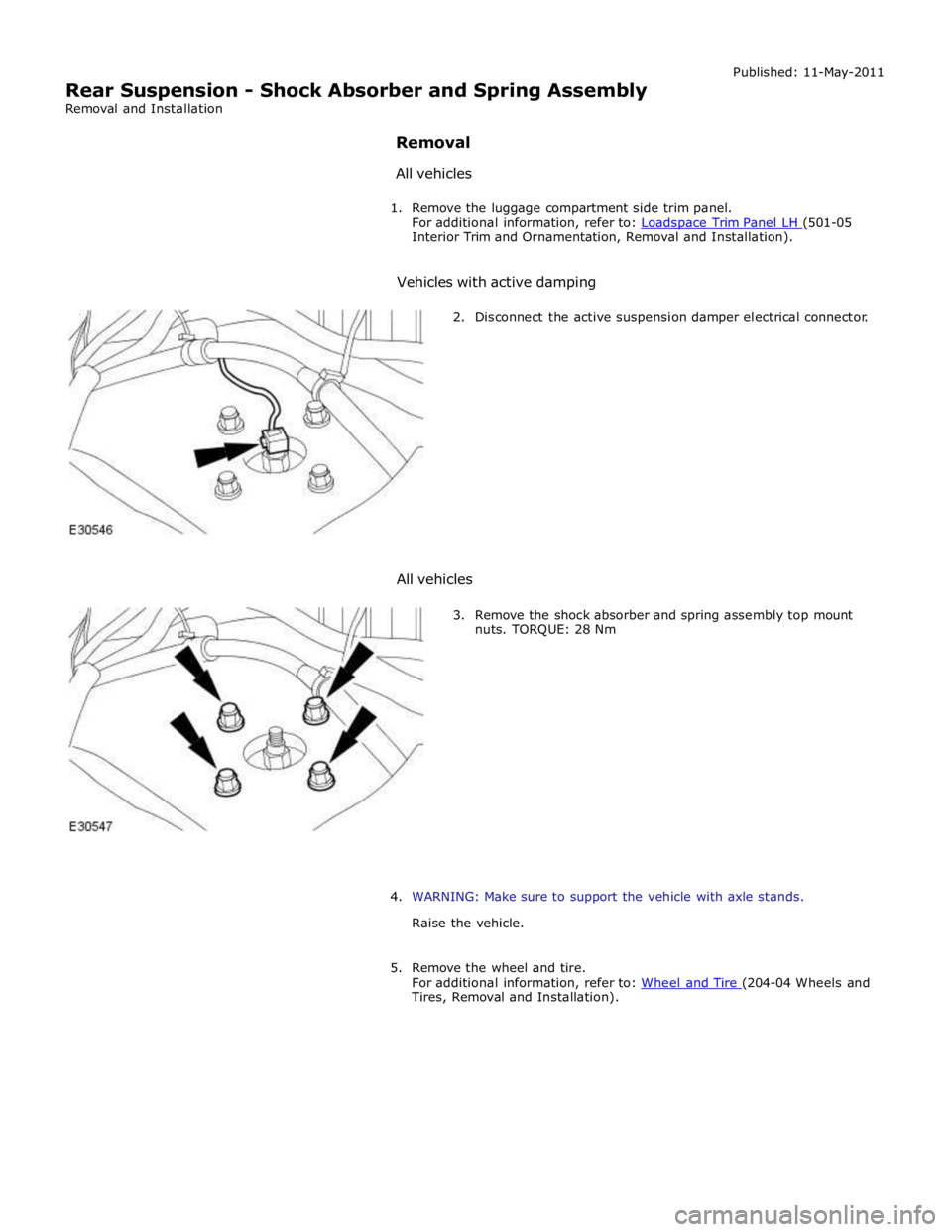
Interior Trim and Ornamentation, Removal and Installation).
Vehicles with active damping
2. Disconnect the active suspension damper electrical connector.
All vehicles
3. Remove the shock absorber and spring assembly top mount
nuts. TORQUE: 28 Nm
4. WARNING: Make sure to support the vehicle with axle stands.
Raise the vehicle.
5. Remove the wheel and tire.
For additional information, refer to: Wheel and Tire (204-04 Wheels and Tires, Removal and Installation).
Page 404 of 3039
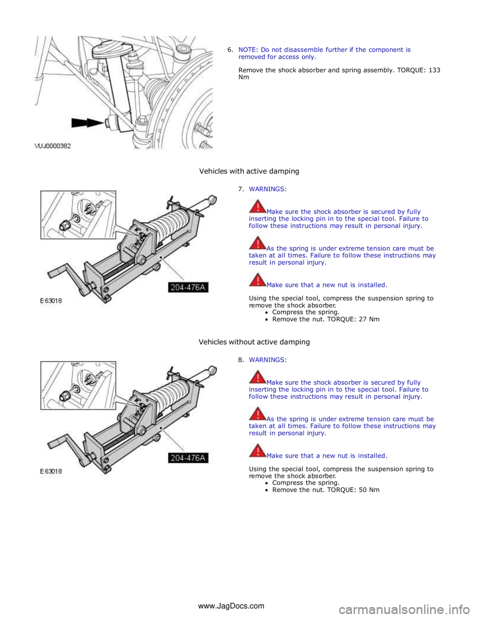
6. NOTE: Do not disassemble further if the component is
removed for access only.
Remove the shock absorber and spring assembly. TORQUE: 133
Nm
Vehicles with active damping
7. WARNINGS:
Make sure the shock absorber is secured by fully
inserting the locking pin in to the special tool. Failure to
follow these instructions may result in personal injury.
As the spring is under extreme tension care must be
taken at all times. Failure to follow these instructions may
result in personal injury.
Make sure that a new nut is installed.
Using the special tool, compress the suspension spring to
remove the shock absorber.
Compress the spring.
Remove the nut. TORQUE: 27 Nm
Vehicles without active damping
8. WARNINGS:
Make sure the shock absorber is secured by fully
inserting the locking pin in to the special tool. Failure to
follow these instructions may result in personal injury.
As the spring is under extreme tension care must be
taken at all times. Failure to follow these instructions may
result in personal injury.
Make sure that a new nut is installed.
Using the special tool, compress the suspension spring to
remove the shock absorber.
Compress the spring.
Remove the nut. TORQUE: 50 Nm
www.JagDocs.com
Page 406 of 3039
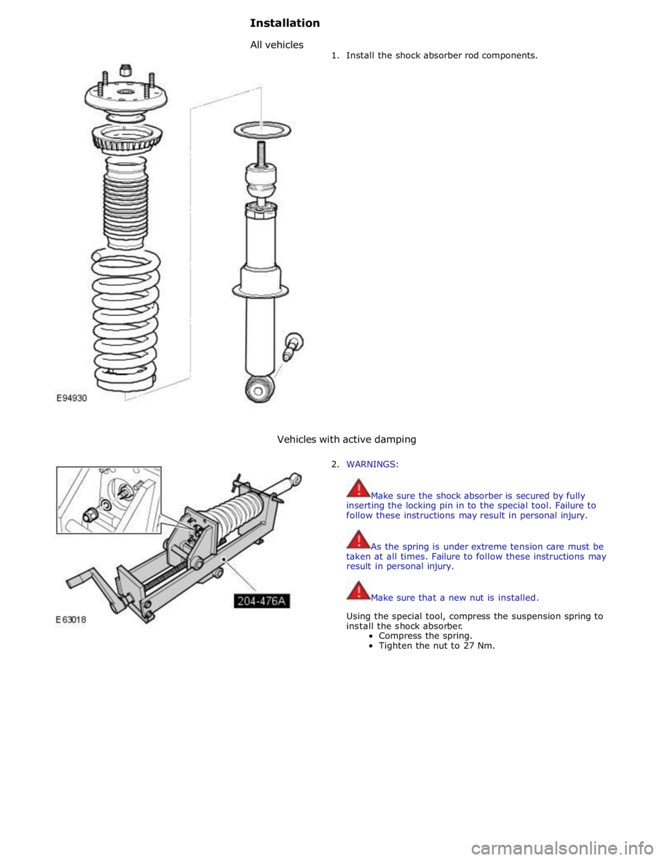
1. Install the shock absorber rod components.
Vehicles with active damping
2. WARNINGS:
Make sure the shock absorber is secured by fully
inserting the locking pin in to the special tool. Failure to
follow these instructions may result in personal injury.
As the spring is under extreme tension care must be
taken at all times. Failure to follow these instructions may
result in personal injury.
Make sure that a new nut is installed.
Using the special tool, compress the suspension spring to
install the shock absorber.
Compress the spring.
Tighten the nut to 27 Nm.
Installation
Allvehicles
Page 407 of 3039
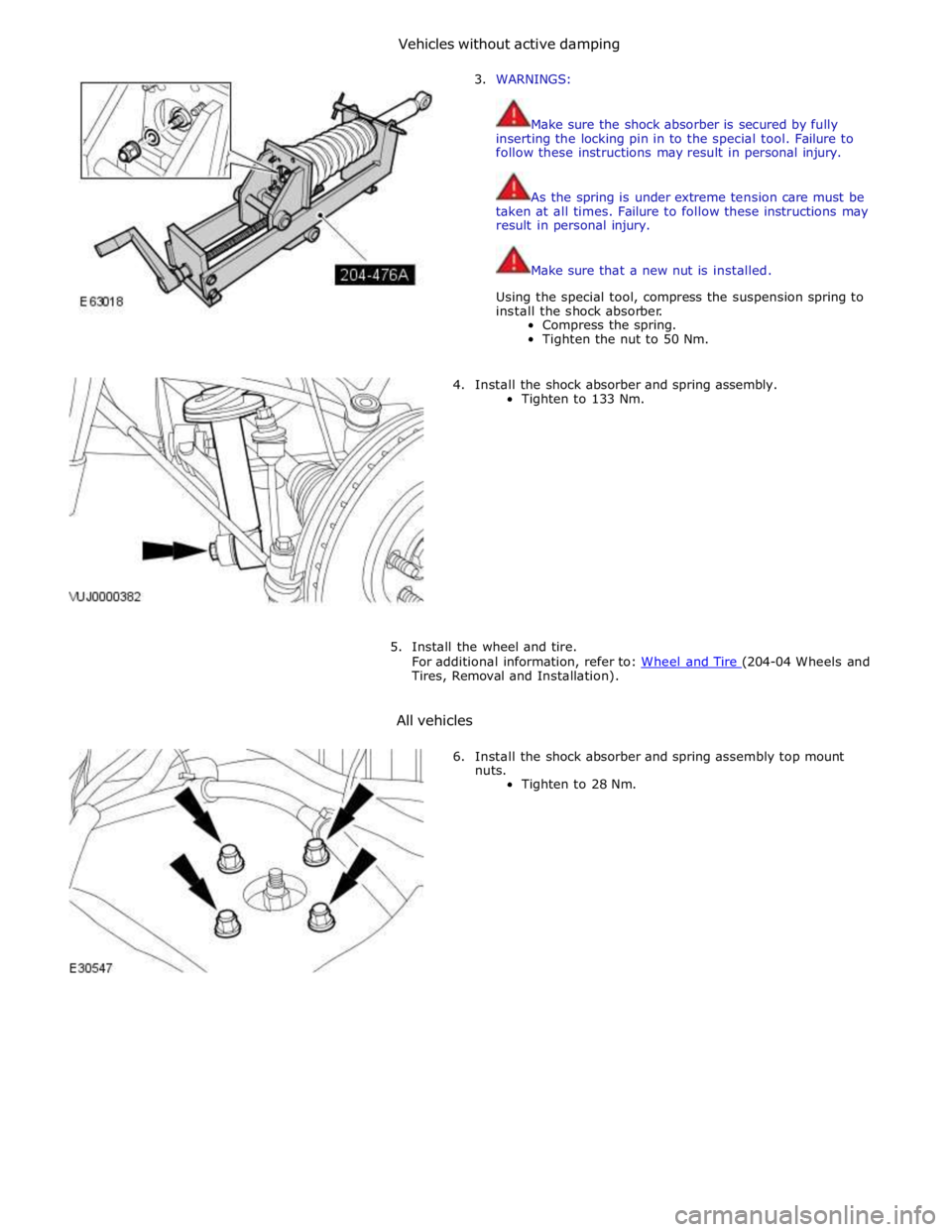
3. WARNINGS:
Make sure the shock absorber is secured by fully
inserting the locking pin in to the special tool. Failure to
follow these instructions may result in personal injury.
As the spring is under extreme tension care must be
taken at all times. Failure to follow these instructions may
result in personal injury.
Make sure that a new nut is installed.
Using the special tool, compress the suspension spring to
install the shock absorber.
Compress the spring.
Tighten the nut to 50 Nm.
4. Install the shock absorber and spring assembly.
Tighten to 133 Nm.
5. Install the wheel and tire.
For additional information, refer to: Wheel and Tire (204-04 Wheels and Tires, Removal and Installation).
All vehicles
6. Install the shock absorber and spring assembly top mount
nuts.
Tighten to 28 Nm.
Vehicleswithoutactivedamping
Page 409 of 3039
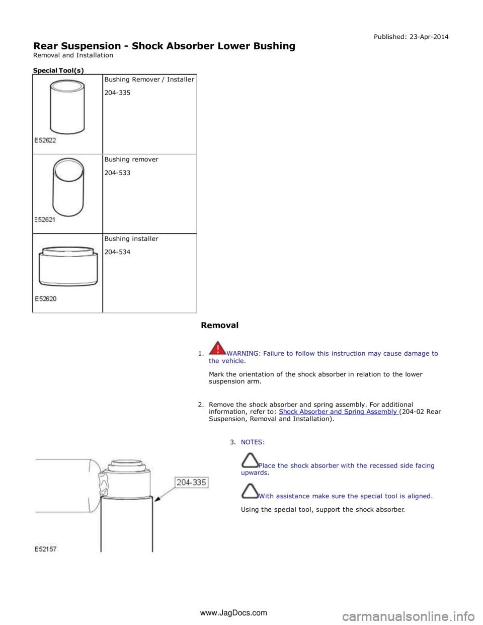
Rear Suspension - Shock Absorber Lower Bushing
Removal and Installation
Special Tool(s)
Bushing Remover / Installer
204-335
Bushing remover
204-533
Bushing installer
204-534
Removal Published: 23-Apr-2014
1. WARNING: Failure to follow this instruction may cause damage to
the vehicle.
Mark the orientation of the shock absorber in relation to the lower
suspension arm.
2. Remove the shock absorber and spring assembly. For additional
information, refer to: Shock Absorber and Spring Assembly (204-02 Rear Suspension, Removal and Installation).
3. NOTES:
Place the shock absorber with the recessed side facing
upwards.
With assistance make sure the special tool is aligned.
Using the special tool, support the shock absorber. www.JagDocs.com
Page 410 of 3039
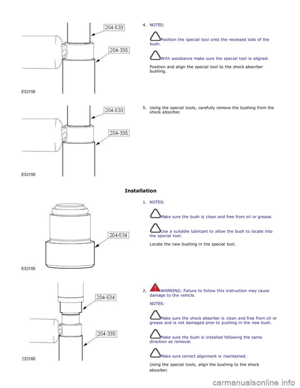
4. NOTES:
bush. Position the special tool onto the recessed side of the
With assistance make sure the special tool is aligned.
Position and align the special tool to the shock absorber
bushing.
5. Using the special tools, carefully remove the bushing from the
shock absorber.
Installation
1. NOTES:
Make sure the bush is clean and free from oil or grease.
Use a suitable lubricant to allow the bush to locate into
the special tool.
Locate the new bushing in the special tool.
2. WARNING: Failure to follow this instruction may cause
damage to the vehicle.
NOTES:
Make sure the shock absorber is clean and free from oil or
grease and is not damaged prior to pushing in the new bush.
Make sure the bush is installed following the same
direction as removal.
Make sure correct alignment is maintained.
Using the special tools, align the bushing to the shock absorber.
Page 411 of 3039
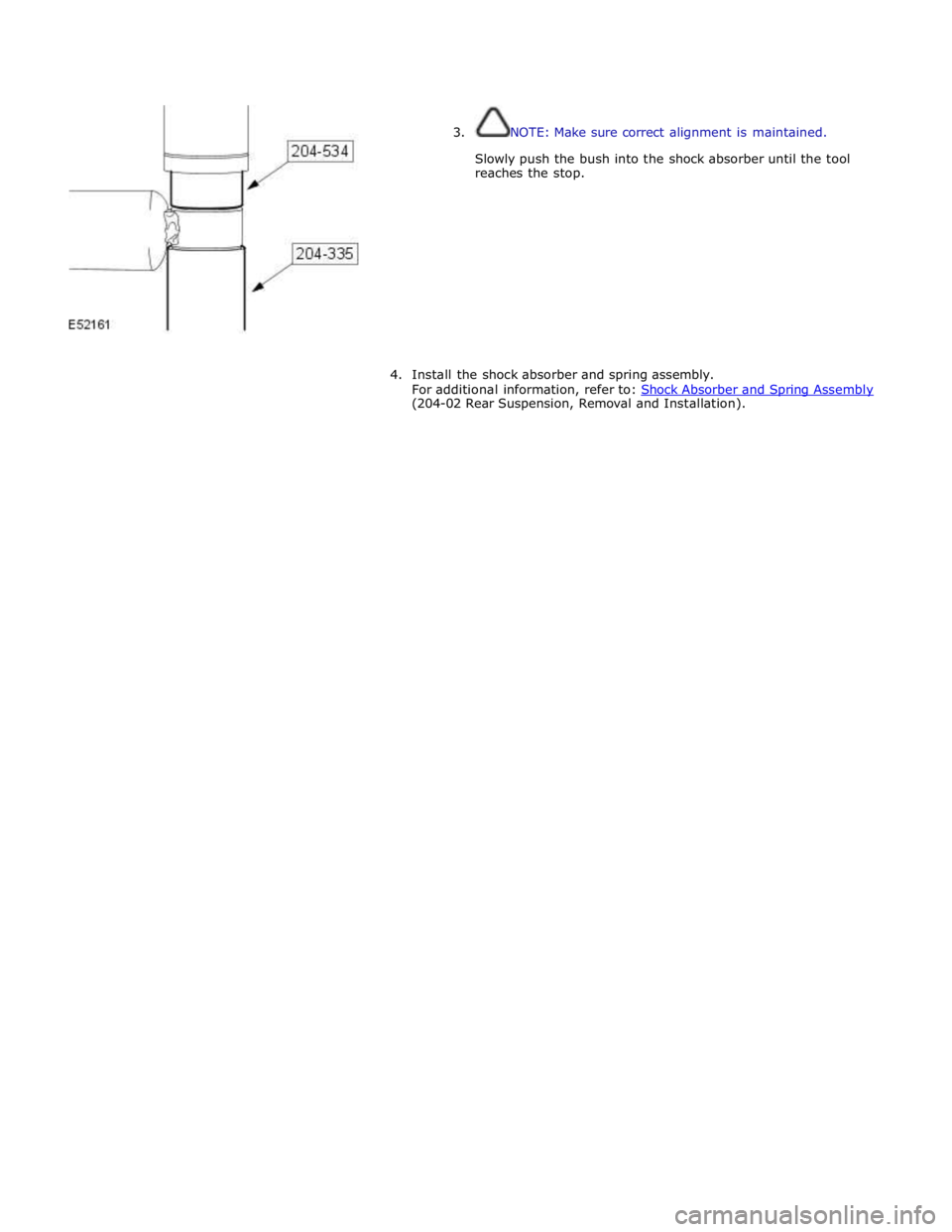
3. NOTE: Make sure correct alignment is maintained.
Slowly push the bush into the shock absorber until the tool
reaches the stop.
4. Install the shock absorber and spring assembly.
For additional information, refer to: Shock Absorber and Spring Assembly (204-02 Rear Suspension, Removal and Installation).
Page 414 of 3039
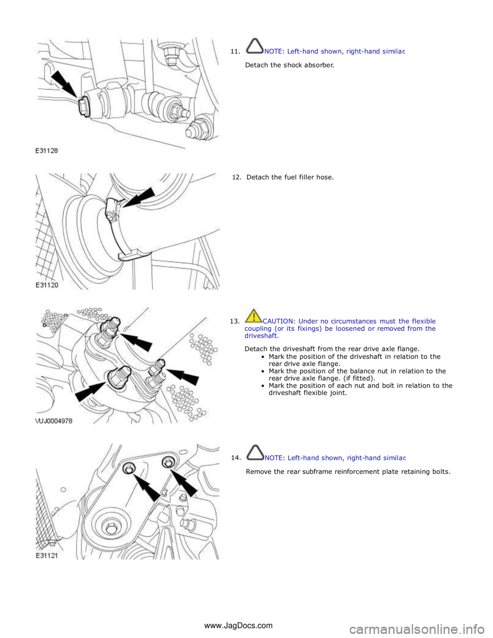
11.
12.
13.
14. NOTE: Left-hand shown, right-hand similar.
Detach the shock absorber.
Detach the fuel filler hose.
CAUTION: Under no circumstances must the flexible
coupling (or its fixings) be loosened or removed from the
driveshaft.
Detach the driveshaft from the rear drive axle flange.
Mark the position of the driveshaft in relation to the
rear drive axle flange.
Mark the position of the balance nut in relation to the
rear drive axle flange. (if fitted).
Mark the position of each nut and bolt in relation to the
driveshaft flexible joint.
NOTE: Left-hand shown, right-hand similar.
Remove the rear subframe reinforcement plate retaining bolts. www.JagDocs.com
Page 419 of 3039

10.
11.
12. NOTE: Left-hand shown, right-hand similar.
Install the shock absorber.
Tighten to 133 Nm.
NOTE: Install the components to their original fitted
positions.
Attach the driveshaft to the rear drive axle flange.
Attach the fuel filler hose to the fuel tank.
13.
Connect both park brake cables to the rear brake calipers. www.JagDocs.com