spare wheel JAGUAR XFR 2010 1.G Owner's Manual
[x] Cancel search | Manufacturer: JAGUAR, Model Year: 2010, Model line: XFR, Model: JAGUAR XFR 2010 1.GPages: 3039, PDF Size: 58.49 MB
Page 2974 of 3039
Rear End Sheet Metal Repairs - Rear Side Member Section
Removal and Installation
Removal Published: 11-May-2011
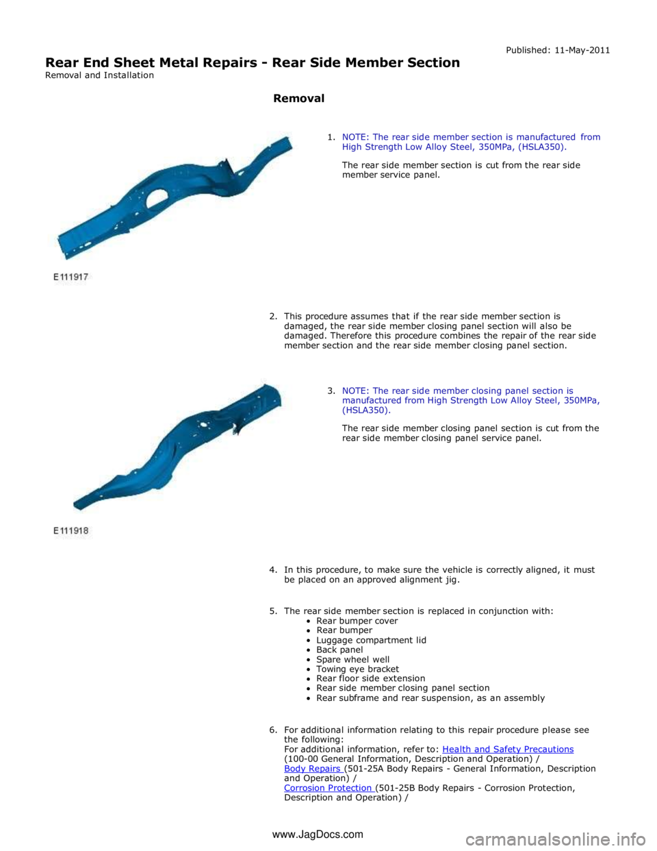
1. NOTE: The rear side member section is manufactured from
High Strength Low Alloy Steel, 350MPa, (HSLA350).
The rear side member section is cut from the rear side
member service panel.
2. This procedure assumes that if the rear side member section is
damaged, the rear side member closing panel section will also be
damaged. Therefore this procedure combines the repair of the rear side
member section and the rear side member closing panel section.
3. NOTE: The rear side member closing panel section is
manufactured from High Strength Low Alloy Steel, 350MPa,
(HSLA350).
The rear side member closing panel section is cut from the
rear side member closing panel service panel.
4. In this procedure, to make sure the vehicle is correctly aligned, it must
be placed on an approved alignment jig.
5. The rear side member section is replaced in conjunction with:
Rear bumper cover
Rear bumper
Luggage compartment lid
Back panel
Spare wheel well
Towing eye bracket
Rear floor side extension
Rear side member closing panel section
Rear subframe and rear suspension, as an assembly
6. For additional information relating to this repair procedure please see
the following:
For additional information, refer to: Health and Safety Precautions (100-00 General Information, Description and Operation) /
Body Repairs (501-25A Body Repairs - General Information, Description and Operation) /
Corrosion Protection (501-25B Body Repairs - Corrosion Protection, Description and Operation) / www.JagDocs.com
Page 2975 of 3039
Body and Frame (501-26 Body Repairs - Vehicle Specific Information and Tolerance Checks, Description and Operation).
7. Disconnect the generator electrical connectors.
8. Remove the luggage compartment lid.
For additional information, refer to: Luggage Compartment Lid (501-03 Body Closures, Removal and Installation).
9. Remove the spare wheel well.
For additional information, refer to: Spare W heel Well (501-30 Rear End Sheet Metal Repairs, Removal and Installation).
10. Remove the rear floor side extension.
For additional information, refer to: Rear Floor Side Extension (501-30 Rear End Sheet Metal Repairs, Removal and Installation).
11. Remove the rear muffler hanger bracket from the side member.
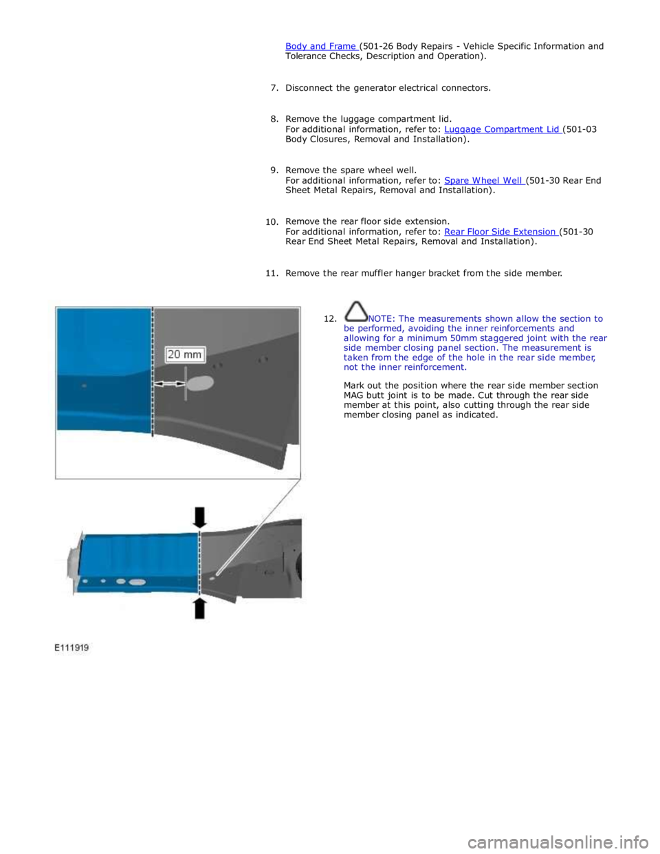
12. NOTE: The measurements shown allow the section to
be performed, avoiding the inner reinforcements and
allowing for a minimum 50mm staggered joint with the rear
side member closing panel section. The measurement is
taken from the edge of the hole in the rear side member,
not the inner reinforcement.
Mark out the position where the rear side member section
MAG butt joint is to be made. Cut through the rear side
member at this point, also cutting through the rear side
member closing panel as indicated.
Page 2992 of 3039
Rear End Sheet Metal Repairs - Spare Wheel Well
Removal and Installation
Removal Published: 11-May-2011
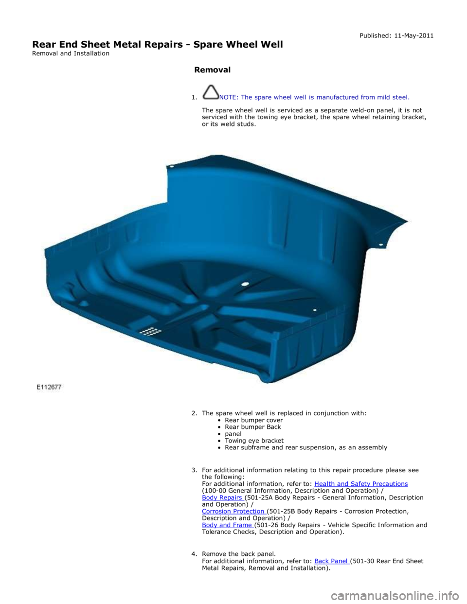
1. NOTE: The spare wheel well is manufactured from mild steel.
The spare wheel well is serviced as a separate weld-on panel, it is not
serviced with the towing eye bracket, the spare wheel retaining bracket,
or its weld studs.
2. The spare wheel well is replaced in conjunction with:
Rear bumper cover
Rear bumper Back
panel
Towing eye bracket
Rear subframe and rear suspension, as an assembly
3. For additional information relating to this repair procedure please see
the following:
For additional information, refer to: Health and Safety Precautions (100-00 General Information, Description and Operation) /
Body Repairs (501-25A Body Repairs - General Information, Description and Operation) /
Corrosion Protection (501-25B Body Repairs - Corrosion Protection, Description and Operation) /
Body and Frame (501-26 Body Repairs - Vehicle Specific Information and Tolerance Checks, Description and Operation).
4. Remove the back panel.
For additional information, refer to: Back Panel (501-30 Rear End Sheet Metal Repairs, Removal and Installation).
Page 2996 of 3039
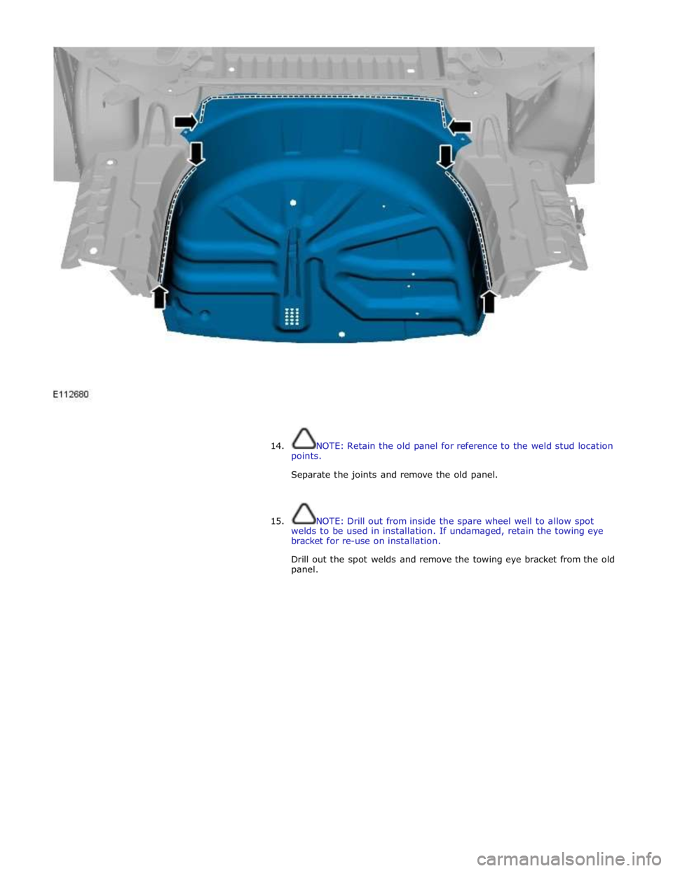
14. NOTE: Retain the old panel for reference to the weld stud location
points.
Separate the joints and remove the old panel.
15. NOTE: Drill out from inside the spare wheel well to allow spot
welds to be used in installation. If undamaged, retain the towing eye
bracket for re-use on installation.
Drill out the spot welds and remove the towing eye bracket from the old
panel.
Page 2997 of 3039
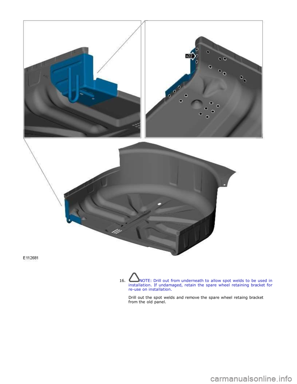
16. NOTE: Drill out from underneath to allow spot welds to be used in
installation. If undamaged, retain the spare wheel retaining bracket for
re-use on installation.
Drill out the spot welds and remove the spare wheel retaing bracket
from the old panel.
Page 2998 of 3039
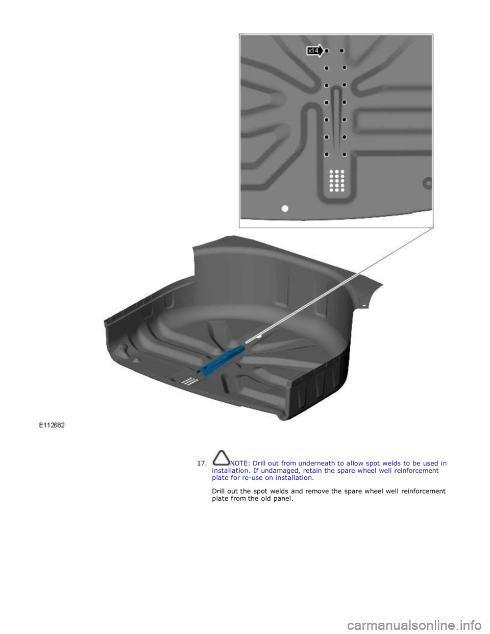
17. NOTE: Drill out from underneath to allow spot welds to be used in
installation. If undamaged, retain the spare wheel well reinforcement
plate for re-use on installation.
Drill out the spot welds and remove the spare wheel well reinforcement
plate from the old panel.
Page 3000 of 3039
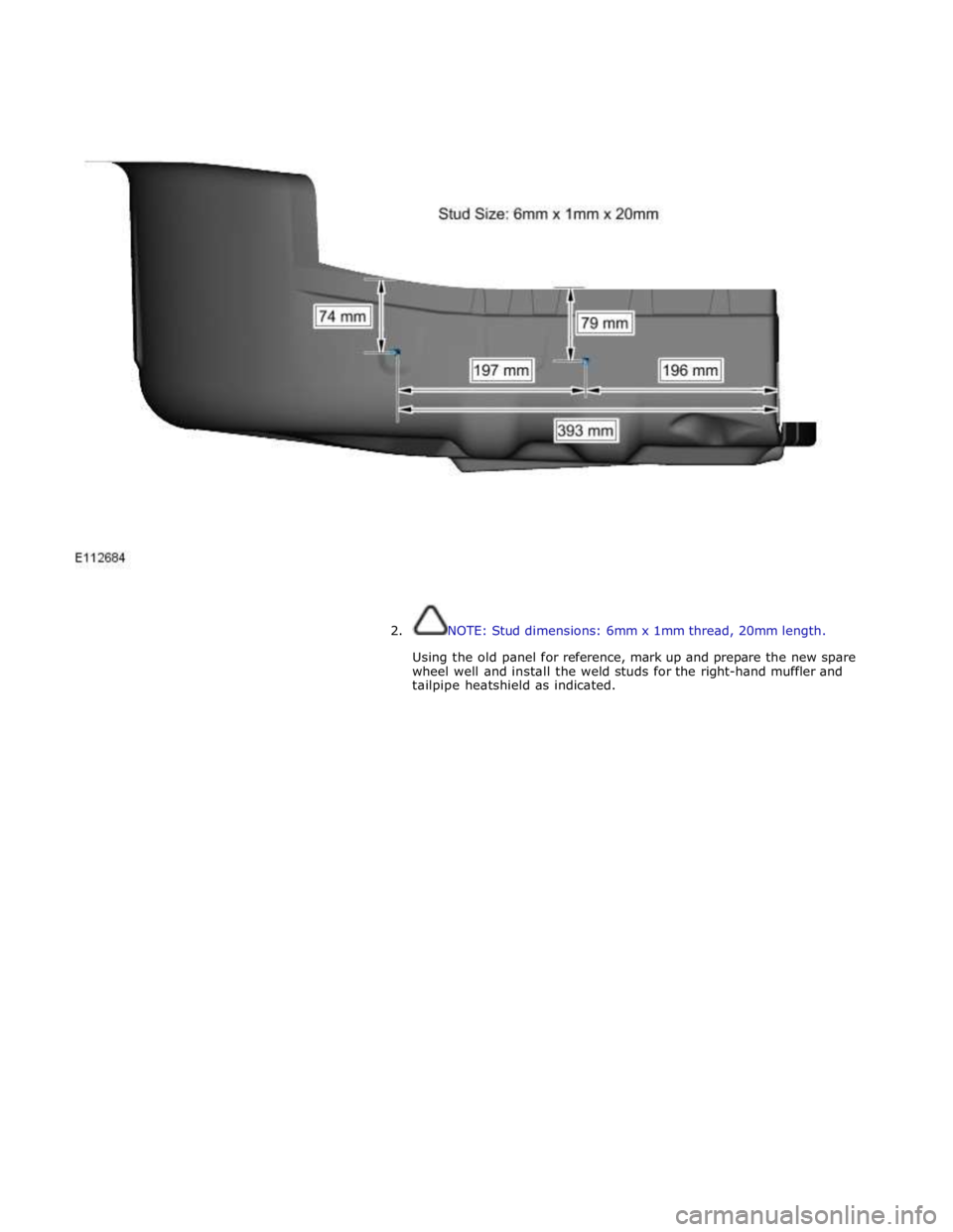
2. NOTE: Stud dimensions: 6mm x 1mm thread, 20mm length.
Using the old panel for reference, mark up and prepare the new spare
wheel well and install the weld studs for the right-hand muffler and
tailpipe heatshield as indicated.
Page 3005 of 3039
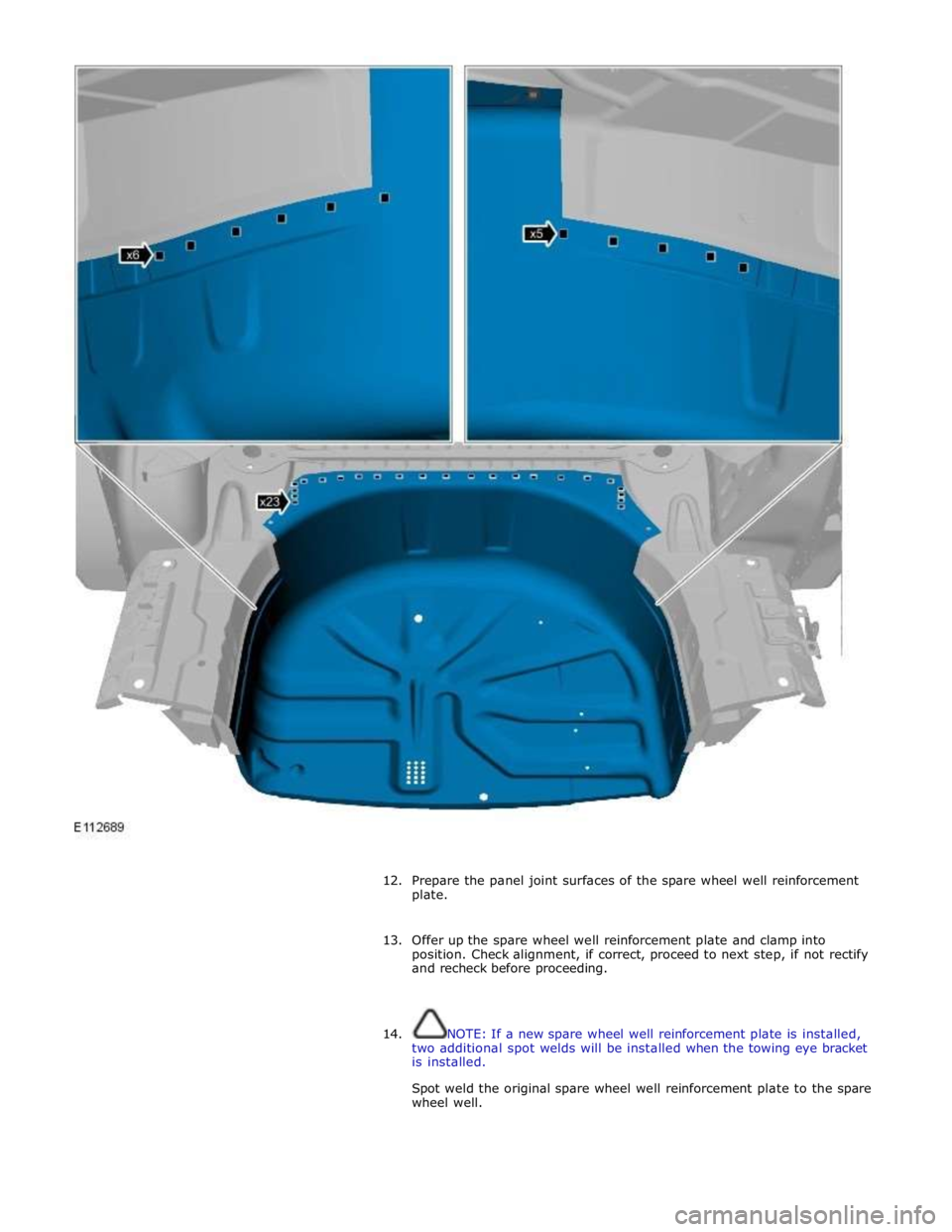
12. Prepare the panel joint surfaces of the spare wheel well reinforcement
plate.
13. Offer up the spare wheel well reinforcement plate and clamp into
position. Check alignment, if correct, proceed to next step, if not rectify
and recheck before proceeding.
14. NOTE: If a new spare wheel well reinforcement plate is installed,
two additional spot welds will be installed when the towing eye bracket
is installed.
Spot weld the original spare wheel well reinforcement plate to the spare
wheel well.
Page 3006 of 3039
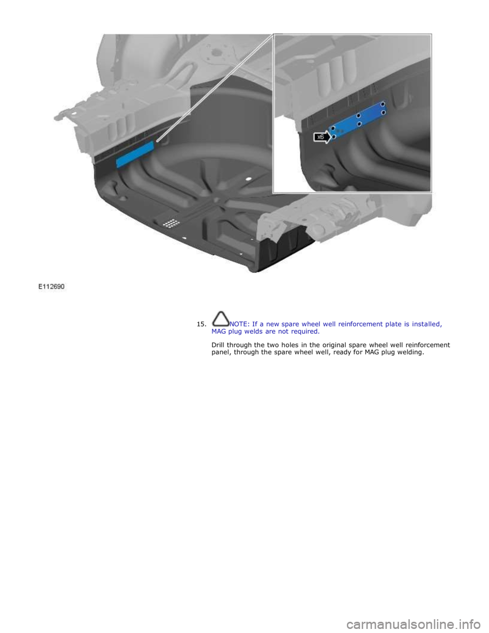
15. NOTE: If a new spare wheel well reinforcement plate is installed,
MAG plug welds are not required.
Drill through the two holes in the original spare wheel well reinforcement
panel, through the spare wheel well, ready for MAG plug welding.
Page 3007 of 3039
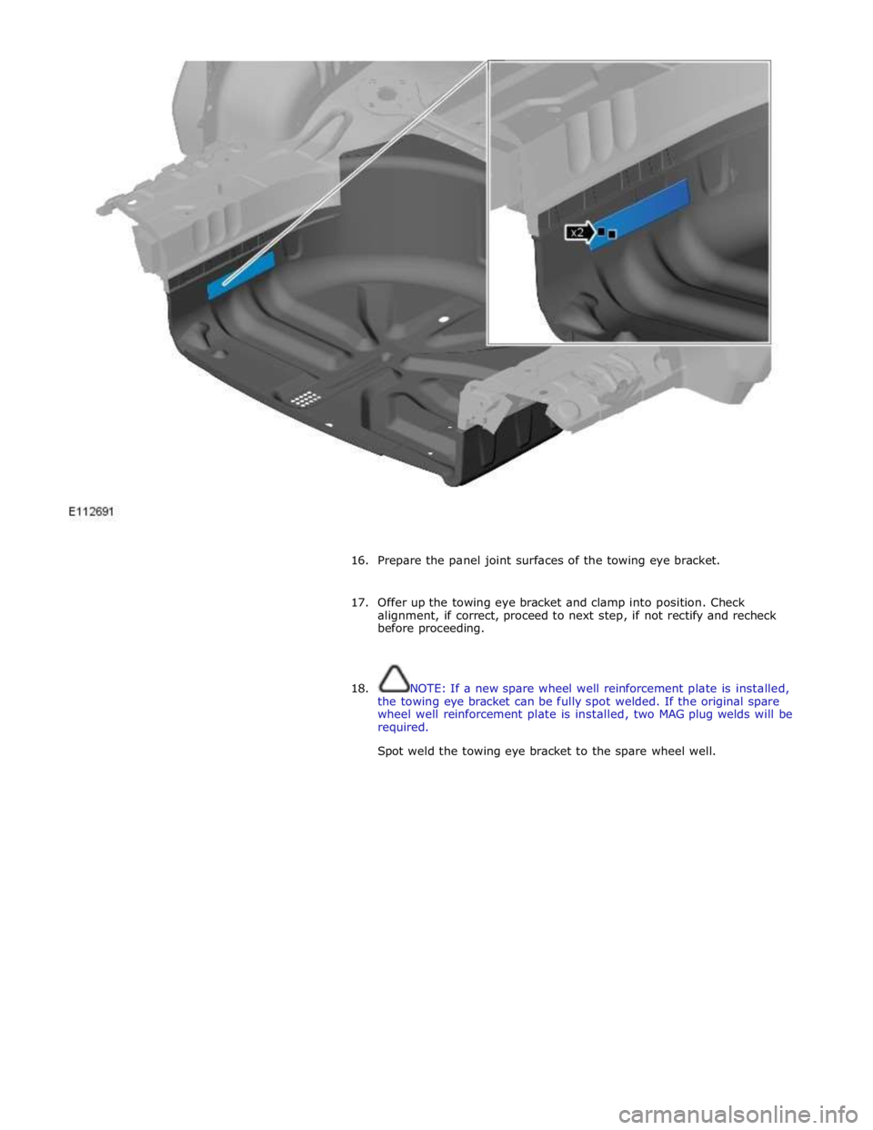
16. Prepare the panel joint surfaces of the towing eye bracket.
17. Offer up the towing eye bracket and clamp into position. Check
alignment, if correct, proceed to next step, if not rectify and recheck
before proceeding.
18. NOTE: If a new spare wheel well reinforcement plate is installed,
the towing eye bracket can be fully spot welded. If the original spare
wheel well reinforcement plate is installed, two MAG plug welds will be
required.
Spot weld the towing eye bracket to the spare wheel well.