list JAGUAR XFR 2010 1.G Service Manual
[x] Cancel search | Manufacturer: JAGUAR, Model Year: 2010, Model line: XFR, Model: JAGUAR XFR 2010 1.GPages: 3039, PDF Size: 58.49 MB
Page 488 of 3039

Vehicle Dynamic Suspension - Vehicle Dynamic Suspension
Diagnosis and Testing
Principle of Operation Published: 09-Jul-2014
For a detailed description of the adaptive damping system operation, refer to the relevant Description and Operation section of
the workshop manual. REFER to: (204-05 Vehicle Dynamic Suspension)
Vehicle Dynamic Suspension - V8 5.0L Petrol/V8 S/C 5.0L Petrol (Description and Operation),
Inspection and Verification
1. Verify the customer concern.
2. Visually inspect for obvious signs of damage and system integrity.
Visual Inspection
Mechanical Electrical
Coil spring(s)
Shock absorber(s)
Accelerometer(s) installation
Height sensor(s) installation
Fuse(s)
Wiring harness/electrical connectors
Accelerometer(s)
Adaptive Damping Control Module
Height sensor(s)
3. If an obvious cause for an observed or reported concern is found, correct the cause (if possible) before proceeding to
the next step.
4. If the cause is not visually evident, check the system for any logged Diagnostic Trouble Codes (DTCs) and refer to the
DTC index.
DTC Index
For a list of Diagnostic Trouble Codes (DTCs) that could be logged on this vehicle, please refer to Section 100-00.
REFER to: Diagnostic Trouble Code (DTC) Index - DTC: Adaptive Damping Module (SUMB) (100-00 General Information, Description and Operation).
Page 538 of 3039
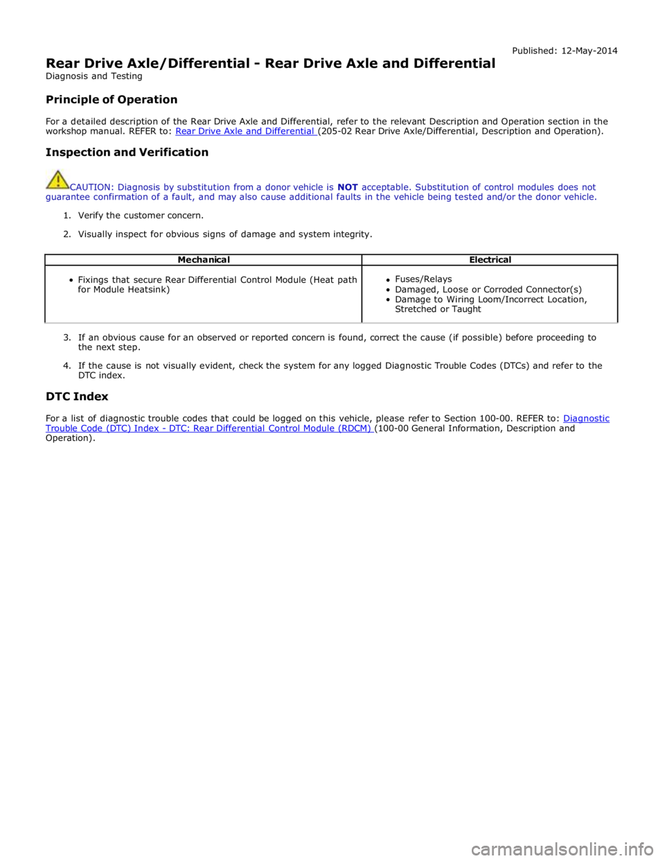
Rear Drive Axle/Differential - Rear Drive Axle and Differential
Diagnosis and Testing
Principle of Operation Published: 12-May-2014
For a detailed description of the Rear Drive Axle and Differential, refer to the relevant Description and Operation section in the
workshop manual. REFER to: Rear Drive Axle and Differential (205-02 Rear Drive Axle/Differential, Description and Operation).
Inspection and Verification
CAUTION: Diagnosis by substitution from a donor vehicle is NOT acceptable. Substitution of control modules does not
guarantee confirmation of a fault, and may also cause additional faults in the vehicle being tested and/or the donor vehicle.
1. Verify the customer concern.
2. Visually inspect for obvious signs of damage and system integrity.
Mechanical Electrical
Fixings that secure Rear Differential Control Module (Heat path
for Module Heatsink)
Fuses/Relays
Damaged, Loose or Corroded Connector(s)
Damage to Wiring Loom/Incorrect Location,
Stretched or Taught
3. If an obvious cause for an observed or reported concern is found, correct the cause (if possible) before proceeding to
the next step.
4. If the cause is not visually evident, check the system for any logged Diagnostic Trouble Codes (DTCs) and refer to the
DTC index.
DTC Index
For a list of diagnostic trouble codes that could be logged on this vehicle, please refer to Section 100-00. REFER to: Diagnostic Trouble Code (DTC) Index - DTC: Rear Differential Control Module (RDCM) (100-00 General Information, Description and Operation).
Page 583 of 3039
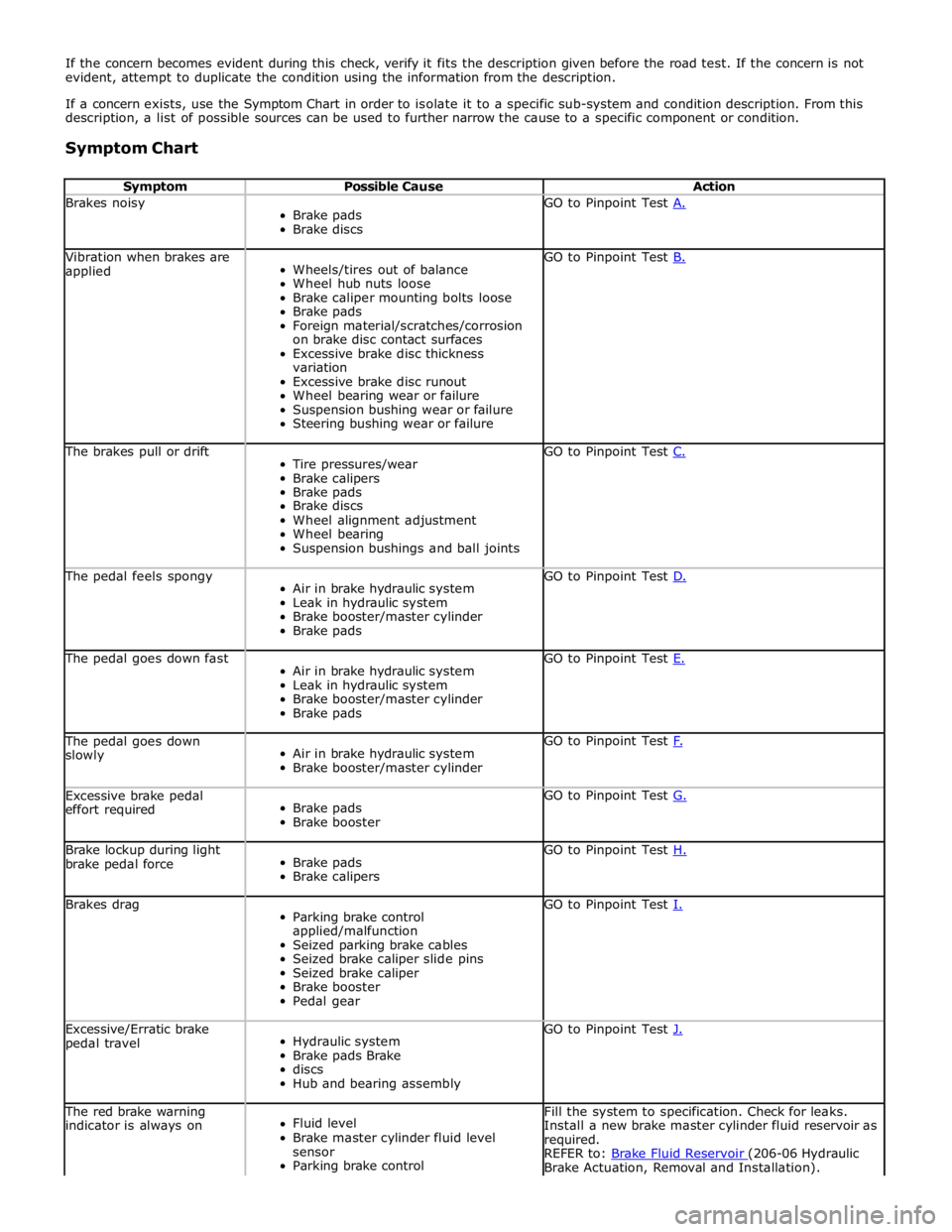
If the concern becomes evident during this check, verify it fits the description given before the road test. If the concern is not
evident, attempt to duplicate the condition using the information from the description.
If a concern exists, use the Symptom Chart in order to isolate it to a specific sub-system and condition description. From this
description, a list of possible sources can be used to further narrow the cause to a specific component or condition.
Symptom Chart
Symptom Possible Cause Action Brakes noisy
Brake pads
Brake discs GO to Pinpoint Test A. Vibration when brakes are
applied
Wheels/tires out of balance
Wheel hub nuts loose
Brake caliper mounting bolts loose
Brake pads
Foreign material/scratches/corrosion
on brake disc contact surfaces
Excessive brake disc thickness
variation
Excessive brake disc runout
Wheel bearing wear or failure
Suspension bushing wear or failure
Steering bushing wear or failure GO to Pinpoint Test B. The brakes pull or drift
Tire pressures/wear
Brake calipers
Brake pads
Brake discs
Wheel alignment adjustment
Wheel bearing
Suspension bushings and ball joints GO to Pinpoint Test C. The pedal feels spongy
Air in brake hydraulic system
Leak in hydraulic system
Brake booster/master cylinder
Brake pads GO to Pinpoint Test D. The pedal goes down fast
Air in brake hydraulic system
Leak in hydraulic system
Brake booster/master cylinder
Brake pads GO to Pinpoint Test E. The pedal goes down
slowly
Air in brake hydraulic system
Brake booster/master cylinder GO to Pinpoint Test F. Excessive brake pedal
effort required
Brake pads
Brake booster GO to Pinpoint Test G. Brake lockup during light
brake pedal force
Brake pads
Brake calipers GO to Pinpoint Test H. Brakes drag
Parking brake control
applied/malfunction
Seized parking brake cables
Seized brake caliper slide pins
Seized brake caliper
Brake booster
Pedal gear GO to Pinpoint Test I. Excessive/Erratic brake
pedal travel
Hydraulic system
Brake pads Brake
discs
Hub and bearing assembly GO to Pinpoint Test J. The red brake warning
indicator is always on
Fluid level
Brake master cylinder fluid level
sensor
Parking brake control Fill the system to specification. Check for leaks.
Install a new brake master cylinder fluid reservoir as
required.
REFER to: Brake Fluid Reservoir (206-06 Hydraulic Brake Actuation, Removal and Installation).
Page 654 of 3039

Symptom Possible Cause Action The parking brake will not
engage or release (with
parking brake warning
message)
Cables fouled, trapped or damaged
Cables incorrectly routed or installed
Rear lining wear
Actuator malfunction
Caliper malfunction
Check the rear and primary
cables for correct installation
and damage
Inspect the rear brake linings for
wear
Re-calibrate the parking brake,
refer to the calibration procedure
Check the rear service brake for
correct installation and operation No communication with the
parking brake module
Fuse
Module off Bus
CAN network error
Parking brake module fault
Check fuses
Ensure battery is fully charged
and in serviceable condition.
Check battery voltage at parking
brake module
Check CAN network using
manufacturer approved
diagnostic system 'Park brake Fault' displayed on
message center with
associated warning lamps
Parking brake system fault
Check the parking brake module
for DTCs and refer to DTC Index Brakes drag
Parking brake not re-calibrated after battery has
been disconnected or has been in a state of
discharge, or repairs have been carried out to
the rear service or parking brake system
Service brake system fault
Re-calibrate parking brake, refer
to the calibration procedure
Check the service brake for
correct operation DTC Index
For a list of diagnostic trouble codes that could be logged on this vehicle, please refer to Section 100-00.
REFER to: Diagnostic Trouble Code (DTC) Index - DTC: Electric Parking Brake (PBM) (100-00 General Information, Description and Operation).
Page 692 of 3039
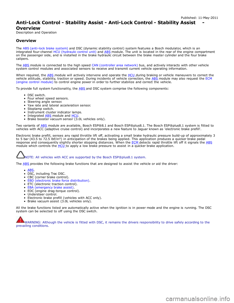
Published: 11-May-2011
Anti-Lock Control - Stability Assist - Anti-Lock Control - Stability Assist - Overview
Description and Operation
Overview
The ABS (anti-lock brake system) and DSC (dynamic stability control) system features a Bosch modulator, which is an
integrated four-channel HCU (hydraulic control unit) and ABS module. The unit is located in the rear of the engine compartment on the passenger side, and is installed in the brake hydraulic circuit between the brake master cylinder and the four brake
calipers.
The ABS module is connected to the high speed CAN (controller area network) bus, and actively interacts with other vehicle system control modules and associated sensors to receive and transmit current vehicle operating information.
When required, the ABS module will actively intervene and operate the HCU during braking or vehicle maneuvers to correct the vehicle attitude, stability, traction or speed. During incidents of vehicle correction, the ABS module may also request the ECM (engine control module) to control engine power in order to further stabilize and correct the vehicle.
To provide full system functionality, the ABS and DSC system comprise the following components: DSC switch.
Four wheel speed sensors.
Steering angle sensor.
Yaw rate and lateral acceleration sensor.
Stoplamp switch.
Instrument cluster indicator lamps.
Integrated ABS module and HCU. Brake booster vacuum sensor (3.0L vehicles only).
Two variants of ABS module are available, Bosch ESP®8.1 and Bosch ESP®plus8.1. The Bosch ESP®plus8.1 system is fitted to vehicles with ACC (adaptive cruise control) and incorporates a new feature to Jaguar known as 'electronic brake prefill'.
Electronic brake prefill, senses any rapid throttle lift off, activating a small brake hydraulic pressure build-up of approximately 3
to 5 bar (43.5 to 72.5 lbf/in²) in anticipation of the brakes being applied. This application produces a quicker brake pedal
response and consequently slightly shorter stopping distances. When the ECM detects rapid throttle lift off it signals the ABS module which controls the HCU to apply a low brake pressure to assist in a quicker brake application.
NOTE: All vehicles with ACC are supported by the Bosch ESP®plus8.1 system.
The ABS provides the following brake functions that are designed to assist the vehicle or aid the driver: ABS. DSC, including Trac DSC.
CBC (corner brake control).
EBD (electronic brake force distribution).
ETC (electronic traction control).
EBA (emergency brake assist).
EDC (engine drag-torque control).
Understeer control.
Electronic brake prefill (vehicles with ACC only).
Brake vacuum assist (3.0L vehicles only).
All the brake functions listed are automatically active when the ignition is in power mode and the engine is running. The DSC
system can be selected to off using the DSC switch.
WARNING: Although the vehicle is fitted with DSC, it remains the drivers responsibility to drive safely according to the
prevailing conditions.
Page 703 of 3039
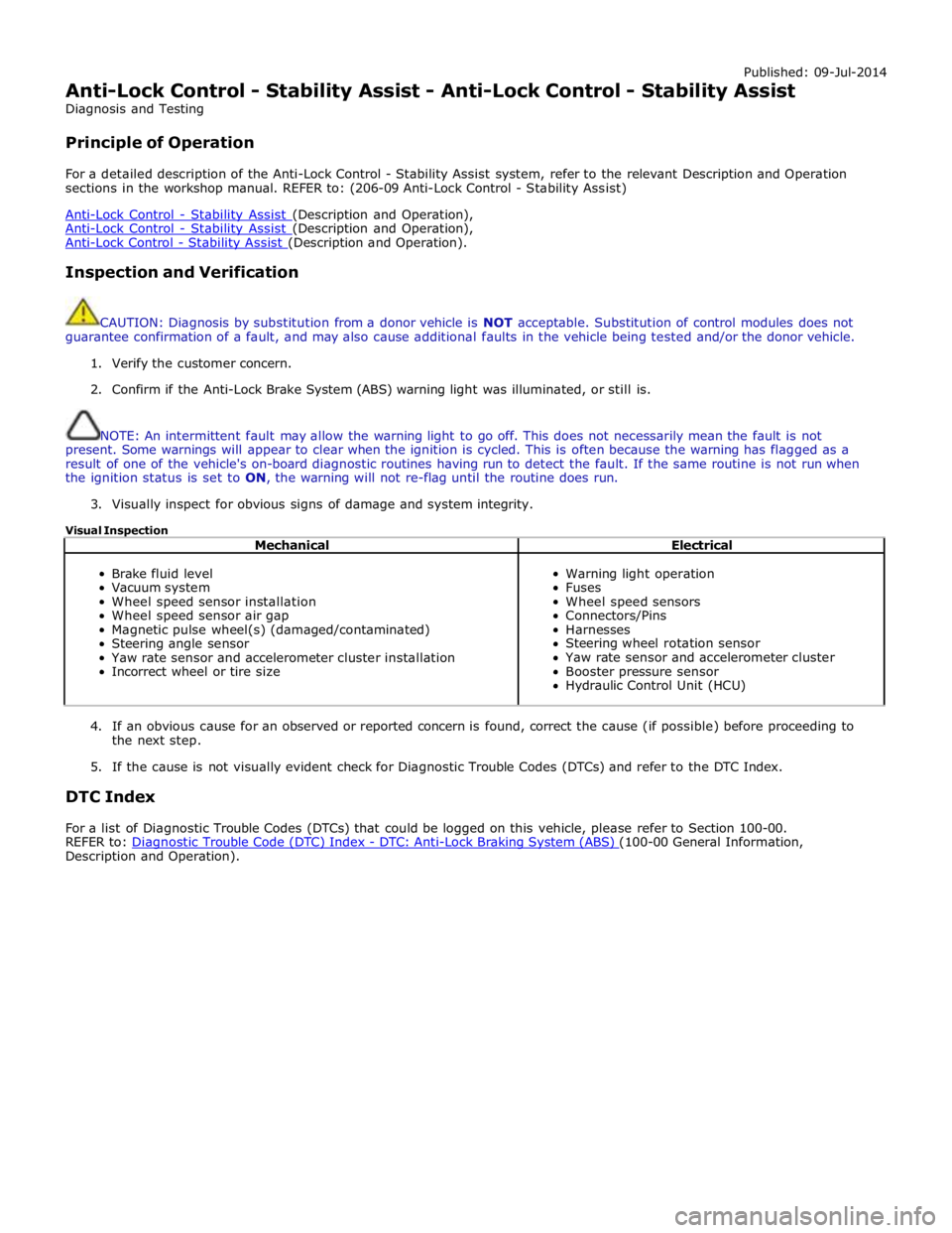
Published: 09-Jul-2014
Anti-Lock Control - Stability Assist - Anti-Lock Control - Stability Assist
Diagnosis and Testing
Principle of Operation
For a detailed description of the Anti-Lock Control - Stability Assist system, refer to the relevant Description and Operation
sections in the workshop manual. REFER to: (206-09 Anti-Lock Control - Stability Assist)
Anti-Lock Control - Stability Assist (Description and Operation), Anti-Lock Control - Stability Assist (Description and Operation), Anti-Lock Control - Stability Assist (Description and Operation).
Inspection and Verification
CAUTION: Diagnosis by substitution from a donor vehicle is NOT acceptable. Substitution of control modules does not
guarantee confirmation of a fault, and may also cause additional faults in the vehicle being tested and/or the donor vehicle.
1. Verify the customer concern.
2. Confirm if the Anti-Lock Brake System (ABS) warning light was illuminated, or still is.
NOTE: An intermittent fault may allow the warning light to go off. This does not necessarily mean the fault is not
present. Some warnings will appear to clear when the ignition is cycled. This is often because the warning has flagged as a
result of one of the vehicle's on-board diagnostic routines having run to detect the fault. If the same routine is not run when
the ignition status is set to ON, the warning will not re-flag until the routine does run.
3. Visually inspect for obvious signs of damage and system integrity.
Visual Inspection
Mechanical Electrical
Brake fluid level
Vacuum system
Wheel speed sensor installation
Wheel speed sensor air gap
Magnetic pulse wheel(s) (damaged/contaminated)
Steering angle sensor
Yaw rate sensor and accelerometer cluster installation
Incorrect wheel or tire size
Warning light operation
Fuses
Wheel speed sensors
Connectors/Pins
Harnesses
Steering wheel rotation sensor
Yaw rate sensor and accelerometer cluster
Booster pressure sensor
Hydraulic Control Unit (HCU)
4. If an obvious cause for an observed or reported concern is found, correct the cause (if possible) before proceeding to
the next step.
5. If the cause is not visually evident check for Diagnostic Trouble Codes (DTCs) and refer to the DTC Index.
DTC Index
For a list of Diagnostic Trouble Codes (DTCs) that could be logged on this vehicle, please refer to Section 100-00.
REFER to: Diagnostic Trouble Code (DTC) Index - DTC: Anti-Lock Braking System (ABS) (100-00 General Information, Description and Operation).
Page 804 of 3039
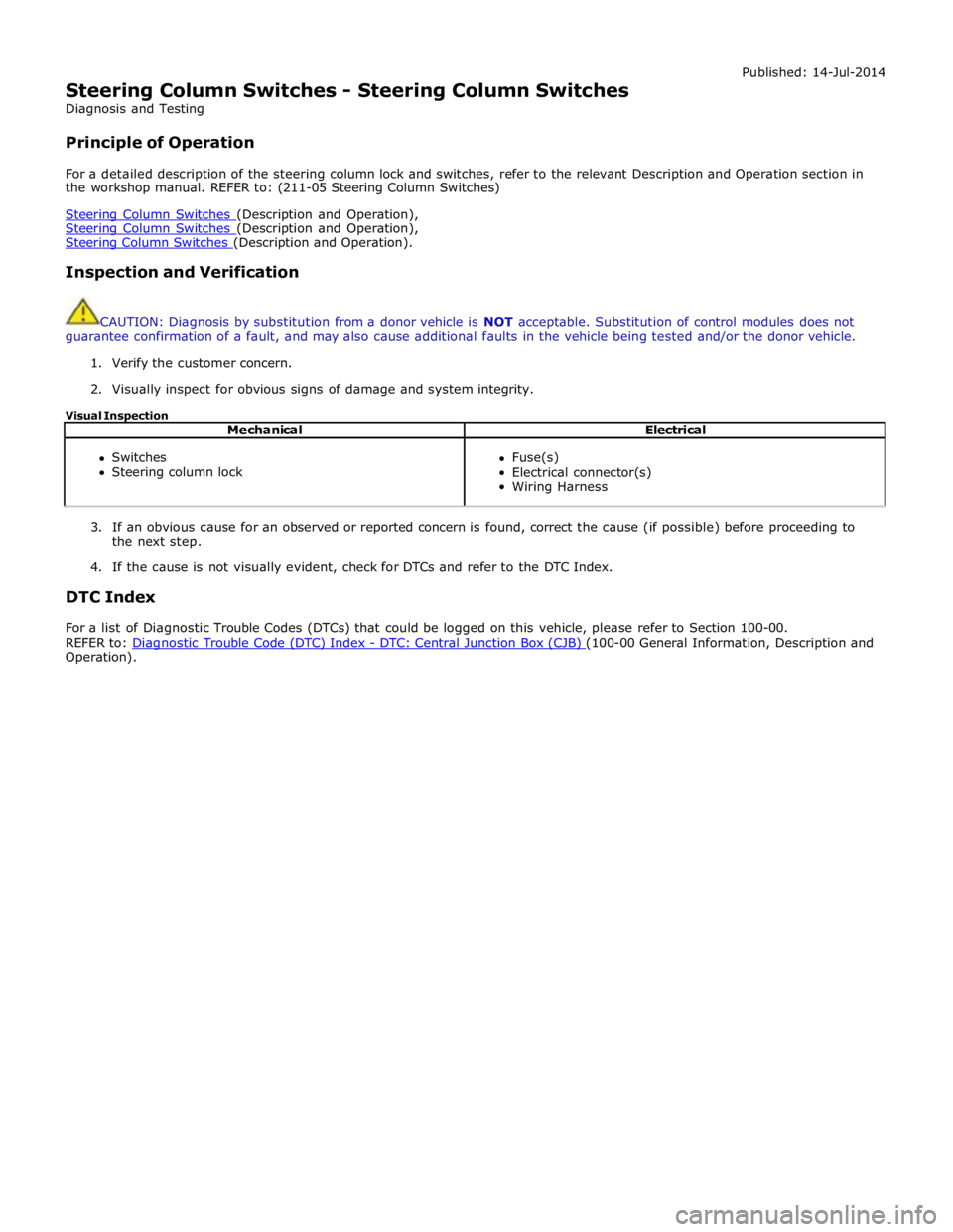
Steering Column Switches - Steering Column Switches
Diagnosis and Testing
Principle of Operation Published: 14-Jul-2014
For a detailed description of the steering column lock and switches, refer to the relevant Description and Operation section in
the workshop manual. REFER to: (211-05 Steering Column Switches)
Steering Column Switches (Description and Operation), Steering Column Switches (Description and Operation), Steering Column Switches (Description and Operation).
Inspection and Verification
CAUTION: Diagnosis by substitution from a donor vehicle is NOT acceptable. Substitution of control modules does not
guarantee confirmation of a fault, and may also cause additional faults in the vehicle being tested and/or the donor vehicle.
1. Verify the customer concern.
2. Visually inspect for obvious signs of damage and system integrity.
Visual Inspection
Mechanical Electrical
Switches
Steering column lock
Fuse(s)
Electrical connector(s)
Wiring Harness
3. If an obvious cause for an observed or reported concern is found, correct the cause (if possible) before proceeding to
the next step.
4. If the cause is not visually evident, check for DTCs and refer to the DTC Index.
DTC Index
For a list of Diagnostic Trouble Codes (DTCs) that could be logged on this vehicle, please refer to Section 100-00.
REFER to: Diagnostic Trouble Code (DTC) Index - DTC: Central Junction Box (CJB) (100-00 General Information, Description and Operation).
Page 812 of 3039
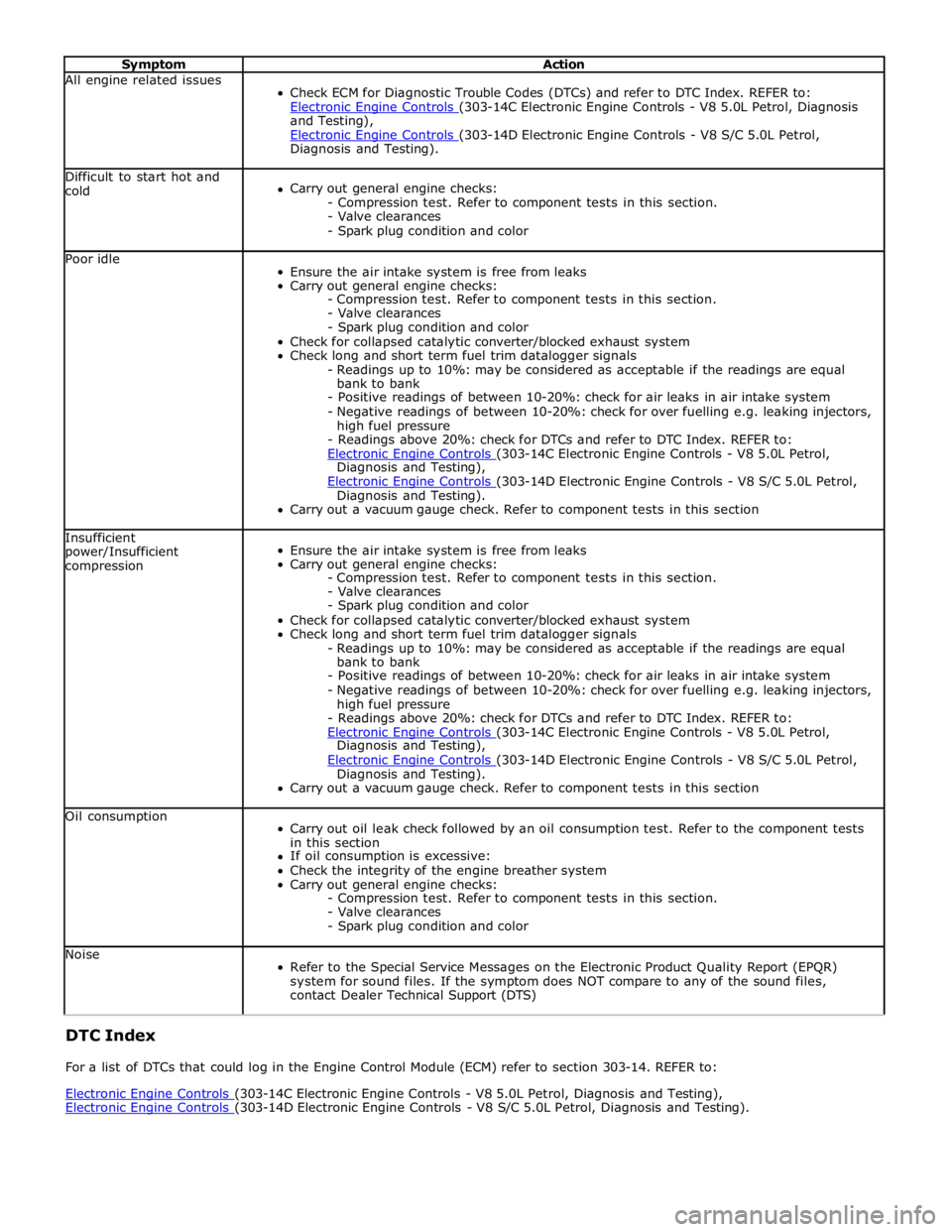
Symptom Action All engine related issues
Check ECM for Diagnostic Trouble Codes (DTCs) and refer to DTC Index. REFER to:
Electronic Engine Controls (303-14C Electronic Engine Controls - V8 5.0L Petrol, Diagnosis and Testing),
Electronic Engine Controls (303-14D Electronic Engine Controls - V8 S/C 5.0L Petrol, Diagnosis and Testing). Difficult to start hot and
cold
Carry out general engine checks:
- Compression test. Refer to component tests in this section.
- Valve clearances
- Spark plug condition and color Poor idle
Ensure the air intake system is free from leaks
Carry out general engine checks:
- Compression test. Refer to component tests in this section.
- Valve clearances
- Spark plug condition and color
Check for collapsed catalytic converter/blocked exhaust system
Check long and short term fuel trim datalogger signals
- Readings up to 10%: may be considered as acceptable if the readings are equal
bank to bank
- Positive readings of between 10-20%: check for air leaks in air intake system
- Negative readings of between 10-20%: check for over fuelling e.g. leaking injectors,
high fuel pressure
- Readings above 20%: check for DTCs and refer to DTC Index. REFER to:
Electronic Engine Controls (303-14C Electronic Engine Controls - V8 5.0L Petrol, Diagnosis and Testing),
Electronic Engine Controls (303-14D Electronic Engine Controls - V8 S/C 5.0L Petrol, Diagnosis and Testing).
Carry out a vacuum gauge check. Refer to component tests in this section Insufficient
power/Insufficient
compression
Ensure the air intake system is free from leaks
Carry out general engine checks:
- Compression test. Refer to component tests in this section.
- Valve clearances
- Spark plug condition and color
Check for collapsed catalytic converter/blocked exhaust system
Check long and short term fuel trim datalogger signals
- Readings up to 10%: may be considered as acceptable if the readings are equal
bank to bank
- Positive readings of between 10-20%: check for air leaks in air intake system
- Negative readings of between 10-20%: check for over fuelling e.g. leaking injectors,
high fuel pressure
- Readings above 20%: check for DTCs and refer to DTC Index. REFER to:
Electronic Engine Controls (303-14C Electronic Engine Controls - V8 5.0L Petrol, Diagnosis and Testing),
Electronic Engine Controls (303-14D Electronic Engine Controls - V8 S/C 5.0L Petrol, Diagnosis and Testing).
Carry out a vacuum gauge check. Refer to component tests in this section Oil consumption
Carry out oil leak check followed by an oil consumption test. Refer to the component tests
in this section
If oil consumption is excessive:
Check the integrity of the engine breather system
Carry out general engine checks:
- Compression test. Refer to component tests in this section.
- Valve clearances
- Spark plug condition and color Noise
Refer to the Special Service Messages on the Electronic Product Quality Report (EPQR)
system for sound files. If the symptom does NOT compare to any of the sound files,
contact Dealer Technical Support (DTS) DTC Index
For a list of DTCs that could log in the Engine Control Module (ECM) refer to section 303-14. REFER to:
Electronic Engine Controls (303-14C Electronic Engine Controls - V8 5.0L Petrol, Diagnosis and Testing), Electronic Engine Controls (303-14D Electronic Engine Controls - V8 S/C 5.0L Petrol, Diagnosis and Testing).
Page 1123 of 3039

Symptom Possible Causes Action Engine coolant
temperature sensor
Restricted air flow
over the radiator Engine not reaching
normal temperature
Thermostat
Cooling fan
Thermostat
Fan speed module Check the thermostat operation. Check the cooling fan operation, make
sure the cooling fan is not seized. Rectify as necessary Engine NOT running.
Cooling fan is
maximum speed
Circuit reference PWM
- Duty cycle is
implausible
Circuit reference PWM
- Frequency out
of range
Circuit reference PWM
- Circuit is open
circuit
Circuit reference PWM
- Circuit is short
circuit to power
Circuit reference PWM
- Circuit is short
circuit to
ground Refer to the electrical circuit diagrams and check the PWM circuit for short
circuit to ground, short circuit to power, open circuit, high resistance Engine IS running.
Cooling fan is
stationary
Circuit reference - IGN
-
- Circuit is open
circuit
Circuit reference - IGN
-
- Circuit is short
circuit to
ground
- EMS fuse
failure
- EMS relay
failure Refer to the electrical circuit diagrams and check the IGN circuit for short
circuit to ground, open circuit, high resistance. Check and install a new EMS
relay and fuse
PINPOINT TEST A : TEST
CONDITIONS DETAILS/RESULTS/ACTIONS A1: CHECK FOR COOLING FAN RELATED DTCS
NOTE: For a complete list of all diagnostic trouble codes that could be logged on this vehicle, please refer
to section 100-00. Generic scan tools may not read the codes listed, or may read only 5-digit codes. Match the
5 digits from the scan tool to the first 5 digits of the 7-digit code listed to identify the fault (the last 2 digits
give extra information read by the manufacturer-approved diagnostic system). 1 Using the manufacturer approved diagnostic system check the engine control module for DTCs 2 P0480-00 & P0480 with any other different last 2 digits in the DTC 3 P0481-00 & P0481 with any other different last 2 digits in the DTC 4 P0483-00 & P0483 with any other different last 2 digits in the DTC Are any of the cooling fan related DTCs listed, logged in the engine control module?
Yes
Please refer to section 100-00 and refer to the relevant DTC index and carry out repair procedure
Using the manufacturer approved diagnostic system clear all stored diagnostic trouble codes from the
diagnosis menu tab
Proceed to the test step A9 'Cooling fan validation procedure'
No
Proceed to the next step. A2 'Check for other DTCs' A2: CHECK FOR OTHER DTCS 1 Using the manufacturer approved diagnostic system check the engine control module for DTCs Are any other DTCs listed, logged in the engine control module?
Yes
Please refer to section 100-00 and refer to the relevant DTC index and carry out repair procedure
Using the manufacturer approved diagnostic system clear all stored diagnostic trouble codes from the
diagnosis menu tab
No
Page 1125 of 3039

- Megafuse fixing nuts
Engine junction box
- Megafuse
- Megafuse fixing nuts
- Fuses
- Engine control module relay Were any circuits or wiring short circuit to ground, short circuit to power, open circuit, high resistance or any
connectors damaged from water ingress, pin damage and/or corrosion?
Yes
Rectify as required
No
Proceed to the next step. A9 'Cooling fan validation procedure' A9: COOLING FAN VALIDATION PROCEDURE 1 Ensure the hood is closed 2 Allow vehicle to idle 3 Switch ON air conditioning and set to lowest temperature and highest fan speed 4 Allow vehicle to reach operating temperature (approximately 90 degrees C). Using the manufacturer approved diagnostic system monitor datalogger signals – Engine Coolant Temperature (0XF405) -and -
Electric Fan PWM Control - Commanded (0X03F9) - as the engine coolant temperature reaches
operating temperature the fan speed should also increase between the values of 9 and 90% Did the cooling fan rotate at increasing speed as engine coolant temperature increased?
Yes
Return vehicle to customer
No
Contact dealer technical support DTC Index
For a list of diagnostic trouble codes (DTCs) that could be logged on this vehicle, please refer to Section 100-00.
REFER to: Electronic Engine Controls (303-14D Electronic Engine Controls - V8 S/C 5.0L Petrol, Diagnosis and Testing). www.JagDocs.com