engine JAGUAR XFR 2010 1.G Repair Manual
[x] Cancel search | Manufacturer: JAGUAR, Model Year: 2010, Model line: XFR, Model: JAGUAR XFR 2010 1.GPages: 3039, PDF Size: 58.49 MB
Page 293 of 3039

left-hand side of the engine below the engine mounting.
Engine Number - 4.2L and 4.2L Supercharged
The serial number is stamped on an engine web on the left-hand side of the cylinder block behind the engine mounting. The
emission code is also located here, on the transmission flange.
Engine Number - 5.0L and 5.0L Supercharged
The serial number is stamped on an engine web on the left-hand side of the cylinder block behind the engine mounting.
Page 297 of 3039
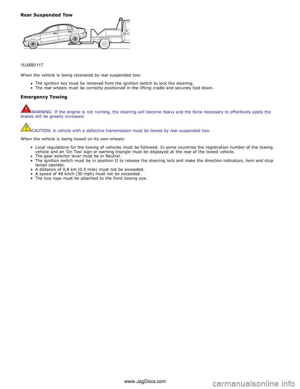
Rear Suspended Tow
When the vehicle is being recovered by rear suspended tow:
The ignition key must be removed from the ignition switch to lock the steering.
The rear wheels must be correctly positioned in the lifting cradle and securely tied down.
Emergency Towing
WARNING: If the engine is not running, the steering will become heavy and the force necessary to effectively apply the
brakes will be greatly increased.
CAUTION: A vehicle with a defective transmission must be towed by rear suspended tow.
When the vehicle is being towed on its own wheels:
Local regulations for the towing of vehicles must be followed. In some countries the registration number of the towing
vehicle and an 'On Tow' sign or warning triangle must be displayed at the rear of the towed vehicle.
The gear selector lever must be in Neutral.
The ignition switch must be in position II to release the steering lock and make the direction indicators, horn and stop
lamps operate.
A distance of 0,8 km (0.5 mile) must not be exceeded.
A speed of 48 km/h (30 mph) must not be exceeded.
The tow rope must be attached to the front towing eye. www.JagDocs.com
Page 298 of 3039

Published: 11-May-2011
Noise, Vibration and Harshness - Noise, Vibration and Harshness (NVH)
Description and Operation
Noise, vibration and harshness (NVH) is becoming more important as vehicles become more sophisticated and passenger
comfort levels increase. This section is designed to aid in the diagnosis, testing and repair of NVH concerns.
Noise is defined as sounds not associated with the operation of passenger compartment equipment that interface with
customer satisfaction.
Vibration is defined as impulses felt by the customer that are not caused by road surface changes.
Harshness is a ride quality issue where the customer feels that the vehicle response to the road surface is sharply
transmitted to the customer.
Diagnostic Theory
Diagnosis is more than just following a series of interrelated steps in order to find the solution to the specific condition. It is a
way of looking at systems that are not functioning the way they should and finding out why. Also it is knowing how the system
should work and whether it is working correctly.
There are basic rules for diagnosis. If these rules are followed, the cause of the condition is usually found the first time
through the system.
Know the System
Know how the parts go together.
Know how the system operates as well as its limits and what happens when the system goes wrong.
Sometimes this means checking the system against one that is known to be working correctly.
Know the History of the System
A clue in any one of these areas may save time:
How old or new is the system?
What kind of treatment has it had?
Has it been repaired in the past in such a manner that might relate to the present condition?
What is the repair history?
Know the History of the Condition
Did it start suddenly or appear gradually?
Was it related to some other occurrence such as a collision or previous part renewal?
Know how the condition made itself known; it may be an important clue to the cause.
Know the Probability of Certain Conditions Developing
Look for the simple rather than the complex.
For example:
- Electrical conditions usually occur at connections rather than components.
- An engine no-start is more likely to be caused by a loose wire or small adjustment rather than a sheared-off
camshaft.
Know the difference between impossible and improbable. Certain failures in a system can be improbable but still
happen.
New parts are just that, new. It does not mean they are always good functioning parts.
Do Not Cure the Symptom and Leave the Cause
Lowering the pressure in a front tire may correct the condition of a vehicle leaning to one side, but it does not correct the
original condition.
Be Positive the Cause is Found
Double check the findings.
What caused a worn component?
A loose transmission or engine mount could indicate that other mounts are also loose.
Diagnostic Charts
Charts are a simple way of expressing the relationship between basic logic and a physical system of components. They help
discover the cause of a condition in the least time. Diagnostic charts combine many areas of diagnosis into one visual display:
probability of certain things occurring in a system
speed of checking certain components or functions before others
simplicity of carrying out certain tests before others
elimination of checking huge portions of a system by carrying out simple tests
certainty of narrowing down the search to a small portion before carrying out in-depth testing
The fastest way to find a condition is to work with the tools that are available. This means working with proven diagnostic
charts and the correct special equipment for the system.
Page 299 of 3039

Published: 16-Sep-2013
Noise, Vibration and Harshness - Noise, Vibration and Harshness (NVH)
Diagnosis and Testing
Principle of Operation
For a detailed description of Noise, Vibration and Harshness issues, refer to the Description and Operation section of the
workshop manual.
REFER to: Noise, Vibration and Harshness (NVH) (100-04 Noise, Vibration and Harshness, Description and Operation).
Inspection and Verification
1. Verify the customer's concerns by operating the vehicle to duplicate the condition.
2. Visually inspect the vehicle to determine any obvious cause(s) of the concern(s).
3. If the inspection reveals obvious causes that can be readily identified, repair as necessary.
4. If the concern(s) remains after the inspection, determine the symptom(s) and refer to the Symptom Chart.
How To Use This Diagnostic Procedure Section
Noise, vibration and harshness (NVH) concerns have become more important as vehicles have become more sensitive to
these vibrations. This section is designed as an aid to identifying these situations
The section provides diagnostic procedures based on symptoms. If the condition occurs at high speed, for instance, the
most likely place to start is under High Speed Shake
The road test procedure will tell how to sort the conditions into categories and how to tell a vibration from a shake
A series of Road Test Quick Checks is provided to make sure that a cause is either pinpointed or eliminated
Name the condition, proceed to the appropriate section and locate the correct diagnosis. When the condition is
identified, the job is partly done
Follow the diagnostic procedure as outlined
Quick Checks are described within the step, while more involved tests and adjustments are outlined in General
Procedures
Always follow each step exactly and make notes to recall important findings later
Customer Interview
The road test and customer interview (if available) provide information that will help identify the concerns and will provide
direction to the correct starting point for diagnosis.
Identify the Condition
NVH problems usually occur in a number of areas:
tires
engine accessories
suspension
driveline
air leakage (wind noise)
squeaks and rattles
heating ventilation and air conditioning (HVAC)
electrical (e.g. motor noise)
transmission
engine
It is important, therefore, that an NVH concern be isolated into its specific area(s) as soon as possible. The easiest and
quickest way to do this is to carry out the Road Test as outlined.
Noise Diagnostic Procedure
Non-Axle Noise
The five most important sources of non-axle noise are exhaust, tires, roof racks, trim and mouldings, and transmission.
Therefore, make sure that none of the following conditions are the cause of the noise before proceeding with a driveline tear
down and diagnosis.
Under certain conditions, the pitch of the exhaust may sound very much like gear noise. At other times, it can be
mistaken for a wheel bearing rumble
Tires, especially snow tires, can have a high pitched tread whine or roar, similar to gear noise. Radial tires, to some
degree, have this characteristic. Also, any non-standard tire with an unusual tread construction may emit a roar or
whine type noise
Trim and mouldings can also cause whistling or a whining noise
Clunk may be a metallic noise heard when the automatic transmission is engaged in reverse or drive, or it may occur
when the throttle is applied or released. It is caused by backlash somewhere in the driveline
Bearing rumble sounds like marbles being tumbled. This condition is usually caused by a damaged wheel bearing
Page 301 of 3039
it may turn out to be the most important.
2. Do not touch anything until a road test and a thorough visual inspection of the vehicle have been carried out. Leave the
tire pressures and vehicle load just where they were when the condition was first observed. Adjusting tire pressures,
vehicle load or making other adjustments may reduce the conditions intensity to a point where it cannot be identified
clearly. It may also inject something new into the system, preventing correct diagnosis.
3. Make a visual inspection as part of the preliminary diagnosis routine, writing down anything that does not look right.
Note tire pressures, but do not adjust them yet. Note leaking fluids, loose nuts and bolts, or bright spots where
components may be rubbing against each other. Check the luggage compartment for unusual loads.
4. Road test the vehicle and define the condition by reproducing it several times during the road test.
5. Carry out the Road Test Quick Checks as soon as the condition is reproduced. This will identify the correct diagnostic
procedure. Carry out the Road Test Quick Checks more than once to verify they are providing a valid result. Remember,
the Road Test Quick Checks may not tell where the concern is, but they will tell where it is not.
Road Test Quick Checks
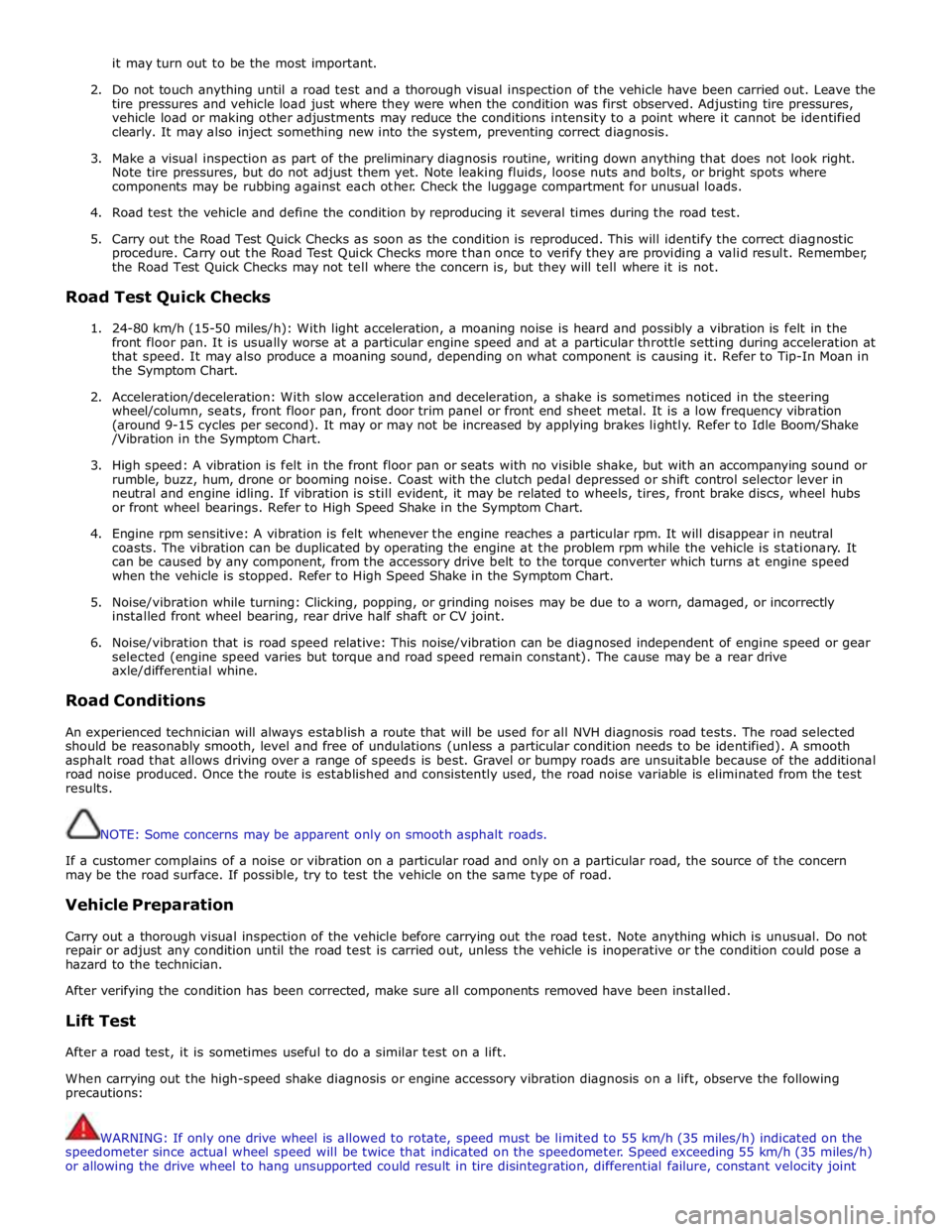
1. 24-80 km/h (15-50 miles/h): With light acceleration, a moaning noise is heard and possibly a vibration is felt in the
front floor pan. It is usually worse at a particular engine speed and at a particular throttle setting during acceleration at
that speed. It may also produce a moaning sound, depending on what component is causing it. Refer to Tip-In Moan in
the Symptom Chart.
2. Acceleration/deceleration: With slow acceleration and deceleration, a shake is sometimes noticed in the steering
wheel/column, seats, front floor pan, front door trim panel or front end sheet metal. It is a low frequency vibration
(around 9-15 cycles per second). It may or may not be increased by applying brakes lightly. Refer to Idle Boom/Shake
/Vibration in the Symptom Chart.
3. High speed: A vibration is felt in the front floor pan or seats with no visible shake, but with an accompanying sound or
rumble, buzz, hum, drone or booming noise. Coast with the clutch pedal depressed or shift control selector lever in
neutral and engine idling. If vibration is still evident, it may be related to wheels, tires, front brake discs, wheel hubs
or front wheel bearings. Refer to High Speed Shake in the Symptom Chart.
4. Engine rpm sensitive: A vibration is felt whenever the engine reaches a particular rpm. It will disappear in neutral
coasts. The vibration can be duplicated by operating the engine at the problem rpm while the vehicle is stationary. It
can be caused by any component, from the accessory drive belt to the torque converter which turns at engine speed
when the vehicle is stopped. Refer to High Speed Shake in the Symptom Chart.
5. Noise/vibration while turning: Clicking, popping, or grinding noises may be due to a worn, damaged, or incorrectly
installed front wheel bearing, rear drive half shaft or CV joint.
6. Noise/vibration that is road speed relative: This noise/vibration can be diagnosed independent of engine speed or gear
selected (engine speed varies but torque and road speed remain constant). The cause may be a rear drive
axle/differential whine.
Road Conditions
An experienced technician will always establish a route that will be used for all NVH diagnosis road tests. The road selected
should be reasonably smooth, level and free of undulations (unless a particular condition needs to be identified). A smooth
asphalt road that allows driving over a range of speeds is best. Gravel or bumpy roads are unsuitable because of the additional
road noise produced. Once the route is established and consistently used, the road noise variable is eliminated from the test
results.
NOTE: Some concerns may be apparent only on smooth asphalt roads.
If a customer complains of a noise or vibration on a particular road and only on a particular road, the source of the concern
may be the road surface. If possible, try to test the vehicle on the same type of road.
Vehicle Preparation
Carry out a thorough visual inspection of the vehicle before carrying out the road test. Note anything which is unusual. Do not
repair or adjust any condition until the road test is carried out, unless the vehicle is inoperative or the condition could pose a
hazard to the technician.
After verifying the condition has been corrected, make sure all components removed have been installed.
Lift Test
After a road test, it is sometimes useful to do a similar test on a lift.
When carrying out the high-speed shake diagnosis or engine accessory vibration diagnosis on a lift, observe the following
precautions:
WARNING: If only one drive wheel is allowed to rotate, speed must be limited to 55 km/h (35 miles/h) indicated on the
speedometer since actual wheel speed will be twice that indicated on the speedometer. Speed exceeding 55 km/h (35 miles/h)
or allowing the drive wheel to hang unsupported could result in tire disintegration, differential failure, constant velocity joint
Page 302 of 3039
and drive half shaft failure, which could cause serious personal injury and extensive vehicle damage. Failure to follow these
instructions may result in personal injury.
CAUTION: The suspension should not be allowed to hang free. When the CV joint is run at a very high angle, extra
vibration as well as damage to the seals and joints can occur.
The rear suspension lower arm should be supported as far outboard as possible. To bring the vehicle to its correct ride height,
the full weight of the vehicle should be supported in the rear by floor jacks. REFER to: (100-02 Jacking and Lifting)
Jacking (Description and Operation), Lifting (Description and Operation).
1. Raise and support the vehicle. REFER to: (100-02 Jacking and Lifting)
Jacking (Description and Operation), Lifting (Description and Operation).
2. Explore the speed range of interest using the Road Test Quick Checks as previously described.
3. Carry out a coast down in neutral. If the vehicle is free of vibration when operating at a steady indicated speed and
behaves very differently in drive and coast, a transmission concern is likely.
Note, however, that a test on the lift may produce different vibrations and noises than a road test because of the effect of the
lift. It is not unusual to find vibrations on the lift that were not found in the road test. If the condition found on the road can
be duplicated on the lift, carrying out experiments on the lift may save a great deal of time.
Exhaust Neutralization Procedure
1. Raise vehicle on lift and slacken all exhaust fixings.
2. With all fixings loose, neutralize the exhaust system.
3. Tighten all fixings to correct torque, starting at the rear-most point working towards the front of the vehicle.
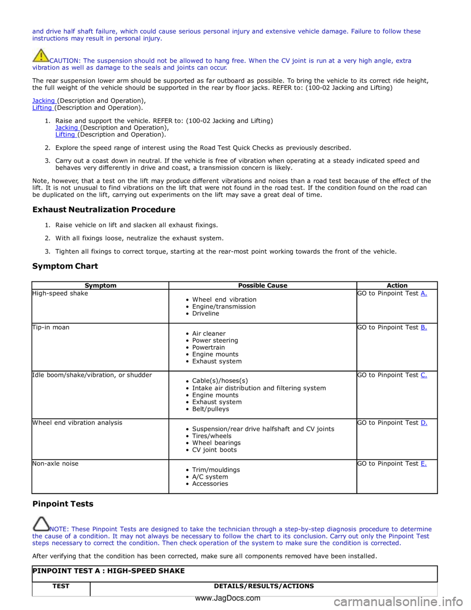
Symptom Chart
Symptom Possible Cause Action High-speed shake
Wheel end vibration
Engine/transmission
Driveline GO to Pinpoint Test A. Tip-in moan
Air cleaner
Power steering
Powertrain
Engine mounts
Exhaust system GO to Pinpoint Test B. Idle boom/shake/vibration, or shudder
Cable(s)/hoses(s)
Intake air distribution and filtering system
Engine mounts
Exhaust system
Belt/pulleys GO to Pinpoint Test C. Wheel end vibration analysis
Suspension/rear drive halfshaft and CV joints
Tires/wheels
Wheel bearings
CV joint boots GO to Pinpoint Test D. Non-axle noise
Trim/mouldings
A/C system
Accessories GO to Pinpoint Test E. Pinpoint Tests
NOTE: These Pinpoint Tests are designed to take the technician through a step-by-step diagnosis procedure to determine
the cause of a condition. It may not always be necessary to follow the chart to its conclusion. Carry out only the Pinpoint Test
steps necessary to correct the condition. Then check operation of the system to make sure the condition is corrected.
After verifying that the condition has been corrected, make sure all components removed have been installed.
PINPOINT TEST A : HIGH-SPEED SHAKE TEST DETAILS/RESULTS/ACTIONS www.JagDocs.com
Page 303 of 3039
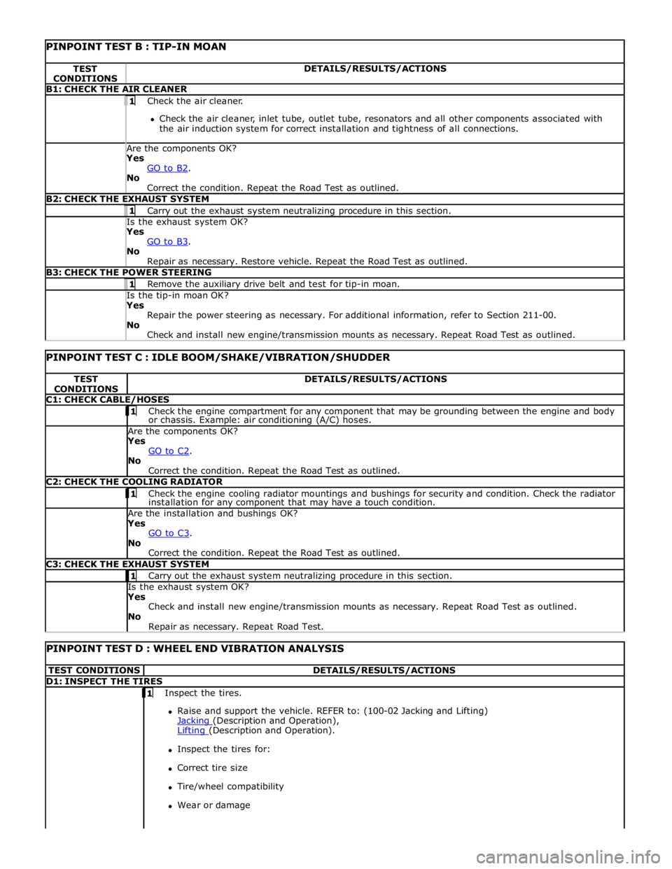
PINPOINT TEST B : TIP-IN MOAN TEST
CONDITIONS DETAILS/RESULTS/ACTIONS B1: CHECK THE AIR CLEANER 1 Check the air cleaner.
Check the air cleaner, inlet tube, outlet tube, resonators and all other components associated with
the air induction system for correct installation and tightness of all connections. Are the components OK? Yes
GO to B2. No
Correct the condition. Repeat the Road Test as outlined. B2: CHECK THE EXHAUST SYSTEM 1 Carry out the exhaust system neutralizing procedure in this section. Is the exhaust system OK? Yes
GO to B3. No
Repair as necessary. Restore vehicle. Repeat the Road Test as outlined. B3: CHECK THE POWER STEERING 1 Remove the auxiliary drive belt and test for tip-in moan. Is the tip-in moan OK? Yes
Repair the power steering as necessary. For additional information, refer to Section 211-00.
No
Check and install new engine/transmission mounts as necessary. Repeat Road Test as outlined.
PINPOINT TEST C : IDLE BOOM/SHAKE/VIBRATION/SHUDDER TEST
CONDITIONS DETAILS/RESULTS/ACTIONS C1: CHECK CABLE/HOSES 1 Check the engine compartment for any component that may be grounding between the engine and body or chassis. Example: air conditioning (A/C) hoses. Are the components OK? Yes
GO to C2. No
Correct the condition. Repeat the Road Test as outlined. C2: CHECK THE COOLING RADIATOR 1 Check the engine cooling radiator mountings and bushings for security and condition. Check the radiator installation for any component that may have a touch condition. Are the installation and bushings OK? Yes
GO to C3. No
Correct the condition. Repeat the Road Test as outlined. C3: CHECK THE EXHAUST SYSTEM 1 Carry out the exhaust system neutralizing procedure in this section. Is the exhaust system OK? Yes
Check and install new engine/transmission mounts as necessary. Repeat Road Test as outlined.
No
Repair as necessary. Repeat Road Test.
PINPOINT TEST D : WHEEL END VIBRATION ANALYSIS TEST CONDITIONS DETAILS/RESULTS/ACTIONS D1: INSPECT THE TIRES 1 Inspect the tires.
Raise and support the vehicle. REFER to: (100-02 Jacking and Lifting)
Jacking (Description and Operation), Lifting (Description and Operation).
Inspect the tires for:
Correct tire size
Tire/wheel compatibility
Wear or damage
Page 332 of 3039

Upper Control Arm
The forged-aluminum upper control arm is a wishbone design and connects to the vehicle body through two plain bushes, and
links to the swan neck wheel knuckle by an integral ball joint. The upper control arm is inclined to provide anti-dive
characteristics under heavy braking, while also controlling geometry for vehicle straight-line stability.
Lower Control Arm
The forged aluminum lower control arms are of the wishbone design; the arms separate to allow for optimum bush tuning:
The rear lateral control arm is fitted with a bush at its inner end which locates between brackets on the subframe. The
arm is secured with an eccentric bolt which provides the adjustment of the suspension camber geometry. The outer end
of the control arm has a tapered hole which locates on a ball joint fitted to the wheel knuckle. An integral clevis bracket
on the forward face of the lateral control arm allows for the attachment of the forward control arm. A bush is fitted
below the clevis bracket to provide for the attachment of the stabilizer bar link. A cross-axis joint is fitted to a
cross-hole in the control arm to provide the location for the clevis attachment of the spring and damper assembly.
The forward control arm is fitted with a fluid-block rubber bush at its inner end which locates between brackets on the
subframe. The arm is secured with an eccentric bolt which provides adjustment of the castor and camber geometry. The
outer end of the control arm is fitted with a cross-axis joint and locates in the integral clevis bracket on the lateral
control arm.
Wheel Knuckle
The cast aluminum wheel knuckle is a swan neck design and attaches to the upper control arm and lower lateral control arm.
The lower lateral control arm locates on a non serviceable ball-joint integral with the wheel knuckle. The lower boss on the
rear of the knuckle provides for the attachment of the steering gear tie-rod ball joint.
The wheel knuckle also provides the mounting locations for the:
wheel hub and bearing assembly
the wheel speed sensor (integral to the wheel hub and bearing assembly)
brake caliper and disc shield.
Stabilizer Bar
The stabilizer bar is attached to the front of the subframe with bushes and mounting brackets. The pressed steel mounting
brackets locate over the bushes and are attached to the cross member with bolts screwed into threaded locations in the
subframe. The stabilizer bar has crimped, 'anti-shuffle' collars pressed in position on the inside edges of the bushes. The
collars prevent sideways movement of the stabilizer bar.
The stabilizer bar is manufactured from 32mm diameter tubular steel on supercharged models and 31mm diameter tubular
steel on diesel and normally aspirated models and has been designed to provide particular characteristics in maintaining roll
rates, specifically in primary ride comfort.
Each end of the stabilizer bar curves rearwards to attach to a ball joint on a stabilizer link. Each stabilizer link is secured to a
bush in the lower lateral arm with a bolt and locknut. The links allow the stabilizer bar to move with the wheel travel providing
maximum effectiveness.
The only difference between the front stabilizer bars, in addition to the diameter, is in the shape to accommodate engine
variant:
a slightly curved bar, between bush centers, for V6 diesel (31 mm dia) and V8 gasoline supercharged (32 mm dia),
a straight bar, between bush centers, for V6 and V8 normally aspirated gasoline engines (31 mm dia).
Spring and Damper Assembly
The spring and damper assemblies are located between the lower lateral arm and the front suspension housing in the inner
wing. Dependant on vehicle model there are three types of coil spring and damper available:
a standard oil passive damper (All models except supercharged),
an adaptive damper, also known as Computer Active Technology Suspension (CATS) on 4.2L supercharged vehicles up to
2010MY, For additional information refer to Vehicle Dynamic Suspension 4.2L.
a continuously variable adaptive damper, also known as Adaptive Dynamics System on 5.0L supercharged vehicles from
2010MY. For additional information refer to Vehicle Dynamic Suspension 5.0L.
The dampers are a monotube design with a spring seat secured by a circlip onto the damper tube. The damper's lower
spherical joint is an integral part of the lateral lower control-arm, and the damper takes the form of a clevis-end, which
straddles the spherical joint.
The damper piston is connected to a damper rod which is sealed at its exit point from the damper body. The threaded outer
end of the damper rod locates through a hole in the top mount. A self locking nut secures the top mount to the damper rod.
The damper rod on the adaptive damper has an electrical connector on the outer end of the damper rod.
Supercharged 4.2L vehicles up to 2010MY: The adaptive damper functions by restricting the flow of hydraulic fluid through
internal galleries in the damper's piston. The adaptive damper has a solenoid operated valve, which when switched allows a
greater flow of hydraulic fluid through the damper's piston. This provides a softer damping characteristic from the damper. The
adaptive damper defaults to a firmer setting when not activated. The solenoid is computer controlled and can switch between
soft and hard damping settings depending on road wheel inputs and vehicle speed.
Supercharged 5.0L vehicles from 2010MY: The variable damper functions by adjustment of a solenoid operated variable orifice,
which opens up an alternative path for oil flow within the damper. When de-energized the bypass is closed and all the oil flows
Page 349 of 3039
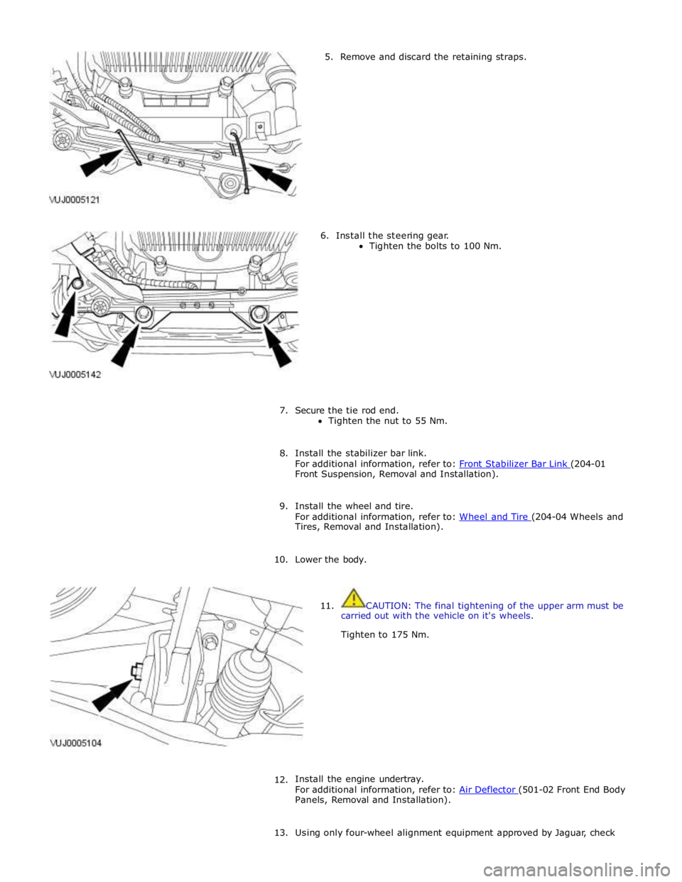
5. Remove and discard the retaining straps.
6. Install the steering gear.
Tighten the bolts to 100 Nm.
7. Secure the tie rod end.
Tighten the nut to 55 Nm.
8. Install the stabilizer bar link.
For additional information, refer to: Front Stabilizer Bar Link (204-01 Front Suspension, Removal and Installation).
9. Install the wheel and tire.
For additional information, refer to: Wheel and Tire (204-04 Wheels and Tires, Removal and Installation).
10. Lower the body.
11. CAUTION: The final tightening of the upper arm must be
carried out with the vehicle on it's wheels.
Tighten to 175 Nm.
12.
Install the engine undertray.
For additional information, refer to: Air Deflector (501-02 Front End Body Panels, Removal and Installation).
13. Using only four-wheel alignment equipment approved by Jaguar, check
Page 356 of 3039
Published: 06-Jun-2013
Front Suspension - Front Stabilizer Bar V8 5.0L Petrol/V8 S/C 5.0L Petrol
Removal and Installation
Removal
NOTE: Removal steps in this procedure may contain installation details.
1. Refer to: Battery Disconnect and Connect (414-01 Battery, Mounting and Cables, General Procedures).
2. WARNING: Do not work on or under a vehicle supported only by a jack.
Always support the vehicle on safety stands.
Raise and support the vehicle.
3. Refer to: Air Conditioning (A/C) System Recovery, Evacuation and Charging (412-00 Climate Control System - General Information, General Procedures).
4. Refer to: Radiator Splash Shield (501-02 Front End Body Panels, Removal and Installation).
5. Refer to: Air Deflector (501-02 Front End Body Panels, Removal and Installation).
6. Refer to: Front Wheel Bearing and Wheel Hub - TDV6 3.0L Diesel /V8 5.0L Petrol/V8 S/C 5.0L Petrol (204-01 Front Suspension, Removal and Installation).
7. Refer to: Engine Cover - V8 5.0L Petrol/V8 S/C 5.0L Petrol (501-05 Interior Trim and Ornamentation, Removal and Installation).
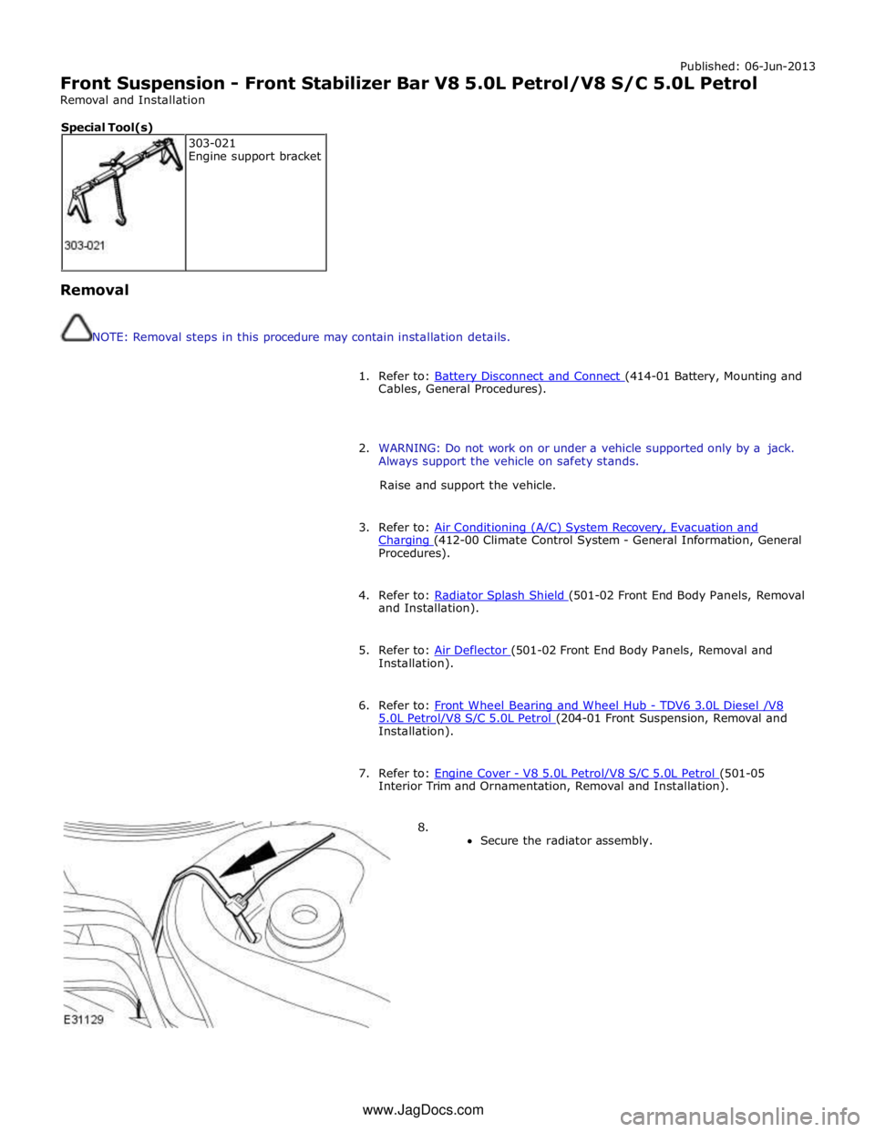
8.
Secure the radiator assembly. 303-021
Engine support bracket Special Tool(s) www.JagDocs.com