fuel pump JAGUAR XFR 2010 1.G Repair Manual
[x] Cancel search | Manufacturer: JAGUAR, Model Year: 2010, Model line: XFR, Model: JAGUAR XFR 2010 1.GPages: 3039, PDF Size: 58.49 MB
Page 1429 of 3039
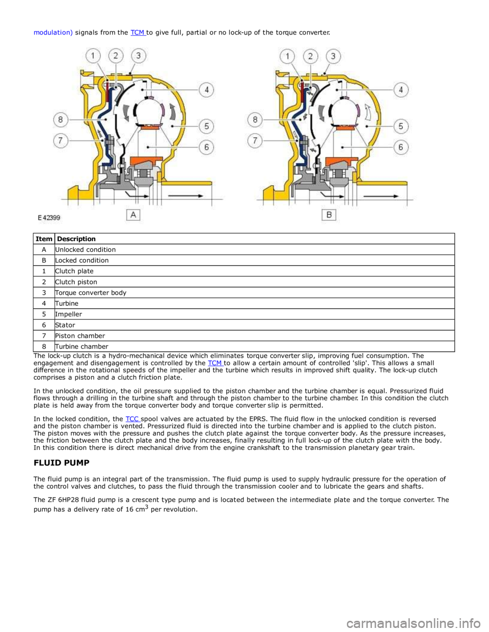
Item Description A Unlocked condition B Locked condition 1 Clutch plate 2 Clutch piston 3 Torque converter body 4 Turbine 5 Impeller 6 Stator 7 Piston chamber 8 Turbine chamber The lock-up clutch is a hydro-mechanical device which eliminates torque converter slip, improving fuel consumption. The
engagement and disengagement is controlled by the TCM to allow a certain amount of controlled 'slip'. This allows a small difference in the rotational speeds of the impeller and the turbine which results in improved shift quality. The lock-up clutch
comprises a piston and a clutch friction plate.
In the unlocked condition, the oil pressure supplied to the piston chamber and the turbine chamber is equal. Pressurized fluid
flows through a drilling in the turbine shaft and through the piston chamber to the turbine chamber. In this condition the clutch
plate is held away from the torque converter body and torque converter slip is permitted.
In the locked condition, the TCC spool valves are actuated by the EPRS. The fluid flow in the unlocked condition is reversed and the piston chamber is vented. Pressurized fluid is directed into the turbine chamber and is applied to the clutch piston.
The piston moves with the pressure and pushes the clutch plate against the torque converter body. As the pressure increases,
the friction between the clutch plate and the body increases, finally resulting in full lock-up of the clutch plate with the body.
In this condition there is direct mechanical drive from the engine crankshaft to the transmission planetary gear train.
FLUID PUMP
The fluid pump is an integral part of the transmission. The fluid pump is used to supply hydraulic pressure for the operation of
the control valves and clutches, to pass the fluid through the transmission cooler and to lubricate the gears and shafts.
The ZF 6HP28 fluid pump is a crescent type pump and is located between the intermediate plate and the torque converter. The
pump has a delivery rate of 16 cm3
per revolution.
Page 1565 of 3039
Published: 01-Aug-2012
Fuel System - General Information - Fuel System Pressure Release V8 5.0L
Petrol/V8 S/C 5.0L Petrol
General Procedures
Draining
1. Remove the fuel pump fuse.
2. Remove the fuel filler cap.
3. CAUTION: When depressurising the fuel system, make sure that
there is no throttle input. Failure to follow this instruction may cause
damage to the vehicle.
Start the engine and allow it to idle until the engine stalls.
4. Crank the engine for approximately five seconds to make sure that the
fuel rail pressure is released.
Filling
1. NOTE: Make sure all repairs have been carried out before
proceeding to the following steps.
Install the fuel pump fuse.
2. Install the fuel filler cap.
3. Read and clear stored DTC fault codes.
Page 1580 of 3039
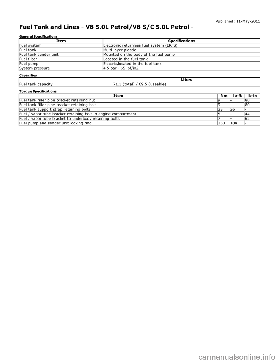
Fuel system Electronic returnless fuel system (ERFS) Fuel tank Multi layer plastic Fuel tank sender unit Mounted on the body of the fuel pump Fuel filter Located in the fuel tank Fuel pump Electric,located in the fuel tank System pressure 4.5 bar - 65 lbf/in2 Capacities Liters Fuel tank capacity 71.1 (total) / 69.5 (useable) Torque Specifications
Item Nm lb-ft lb-in Fuel tank filler pipe bracket retaining nut 9 - 80 Fuel tank filler pipe bracket retaining bolt 9 - 80 Fuel tank support strap retaining bolts 35 26 - Fuel / vapor tube bracket retaining bolt in engine compartment 5 - 44 Fuel / vapor tube bracket to underbody retaining bolts 7 - 62 Fuel pump and sender unit locking ring 250 184 -
Page 1581 of 3039
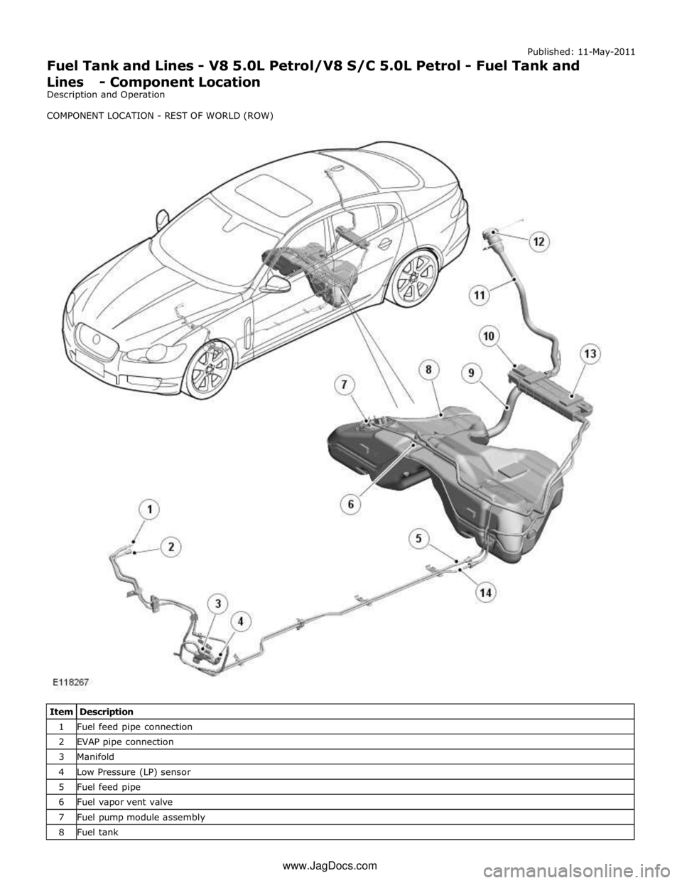
1 Fuel feed pipe connection 2 EVAP pipe connection 3 Manifold 4 Low Pressure (LP) sensor 5 Fuel feed pipe 6 Fuel vapor vent valve 7 Fuel pump module assembly 8 Fuel tank www.JagDocs.com
Page 1582 of 3039
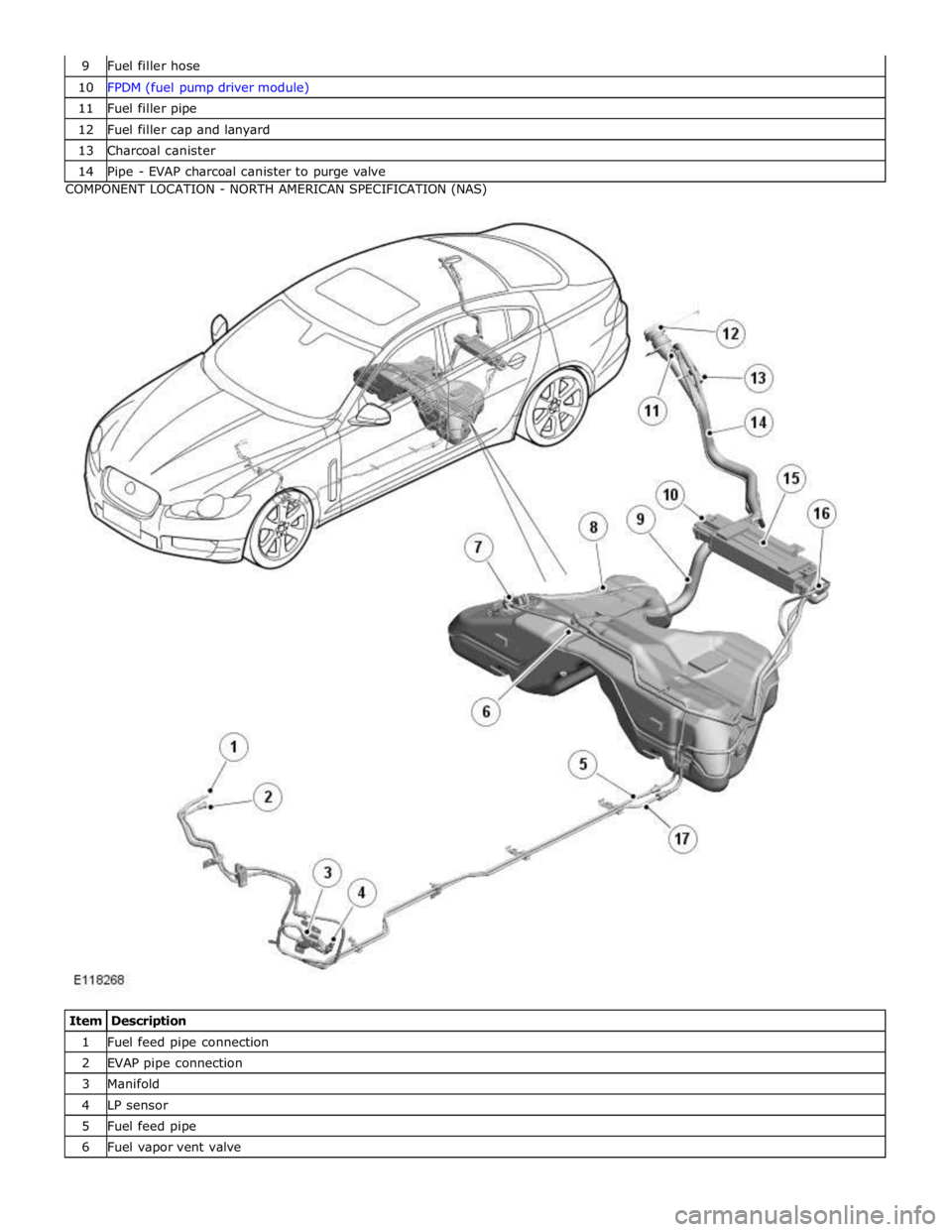
10 FPDM (fuel pump driver module) 11 Fuel filler pipe 12 Fuel filler cap and lanyard 13 Charcoal canister 14 Pipe - EVAP charcoal canister to purge valve COMPONENT LOCATION - NORTH AMERICAN SPECIFICATION (NAS)
Item Description 1 Fuel feed pipe connection 2 EVAP pipe connection 3 Manifold 4 LP sensor 5 Fuel feed pipe 6 Fuel vapor vent valve
Page 1583 of 3039
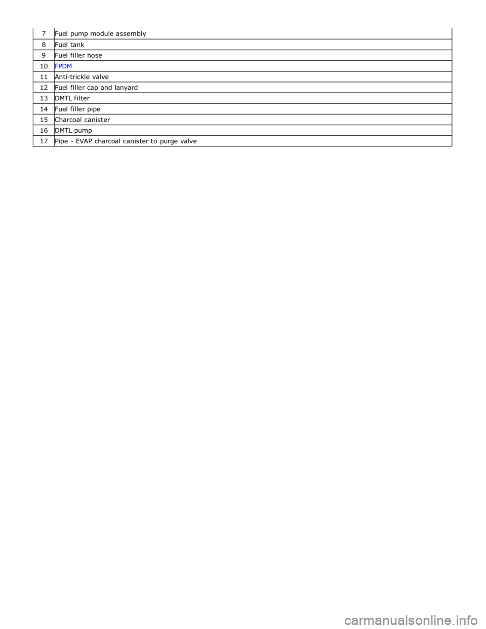
8 Fuel tank 9 Fuel filler hose 10 FPDM 11 Anti-trickle valve 12 Fuel filler cap and lanyard 13 DMTL filter 14 Fuel filler pipe 15 Charcoal canister 16 DMTL pump 17 Pipe - EVAP charcoal canister to purge valve
Page 1584 of 3039
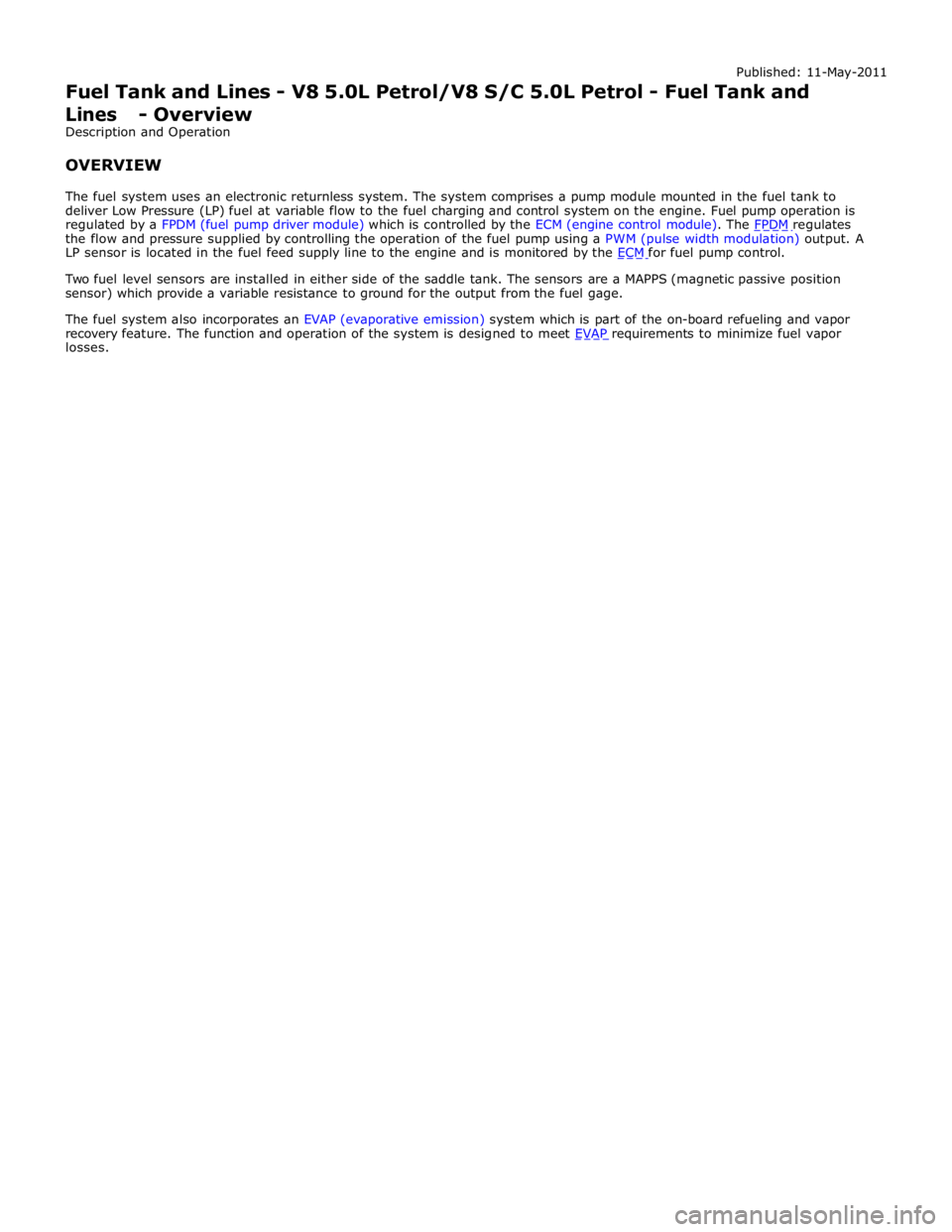
the flow and pressure supplied by controlling the operation of the fuel pump using a PWM (pulse width modulation) output. A
LP sensor is located in the fuel feed supply line to the engine and is monitored by the ECM for fuel pump control.
Two fuel level sensors are installed in either side of the saddle tank. The sensors are a MAPPS (magnetic passive position
sensor) which provide a variable resistance to ground for the output from the fuel gage.
The fuel system also incorporates an EVAP (evaporative emission) system which is part of the on-board refueling and vapor
recovery feature. The function and operation of the system is designed to meet EVAP requirements to minimize fuel vapor losses.
Page 1585 of 3039
Published: 11-May-2011
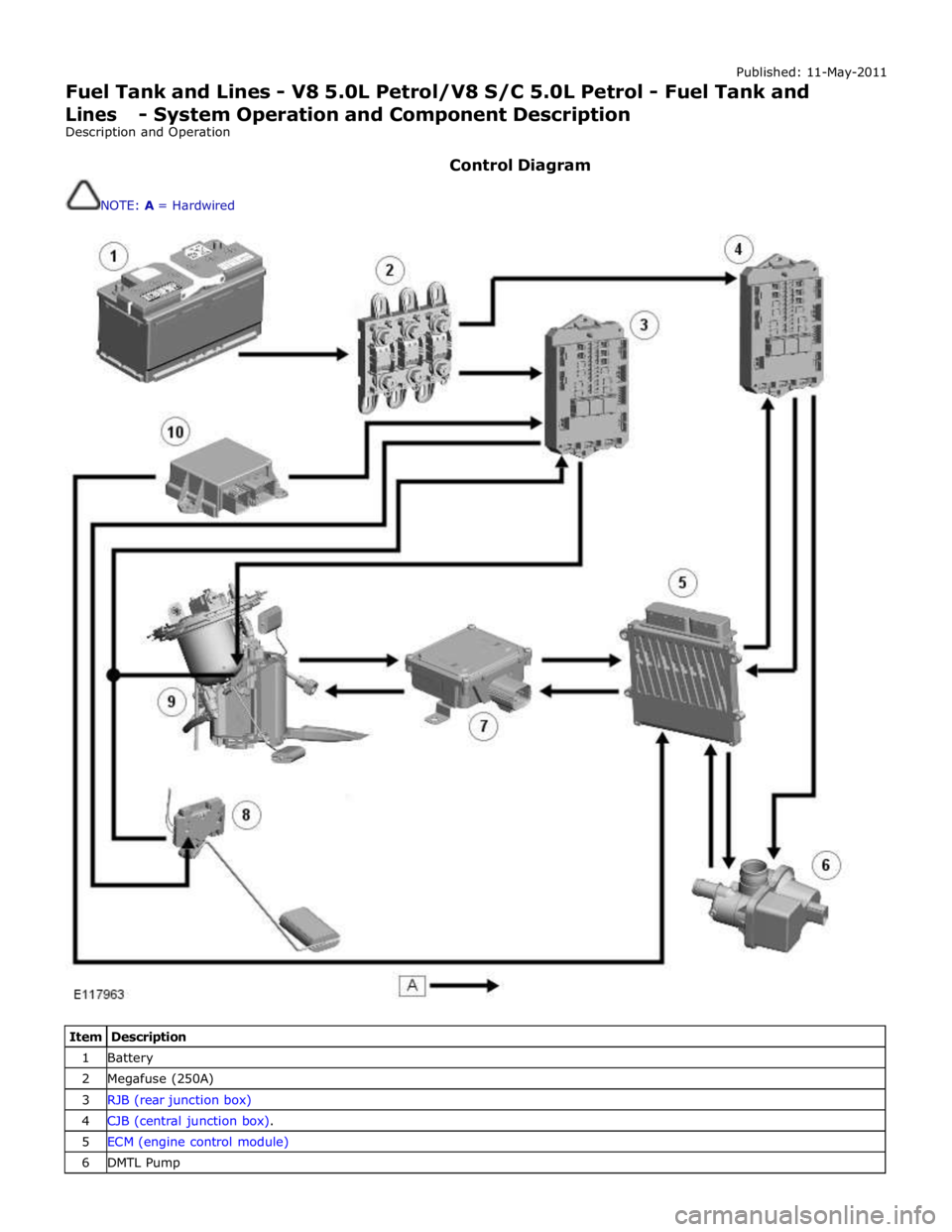
Fuel Tank and Lines - V8 5.0L Petrol/V8 S/C 5.0L Petrol - Fuel Tank and Lines - System Operation and Component Description
Description and Operation
Control Diagram
NOTE: A = Hardwired
Item Description 1 Battery 2 Megafuse (250A) 3 RJB (rear junction box) 4 CJB (central junction box). 5 ECM (engine control module) 6 DMTL Pump
Page 1586 of 3039
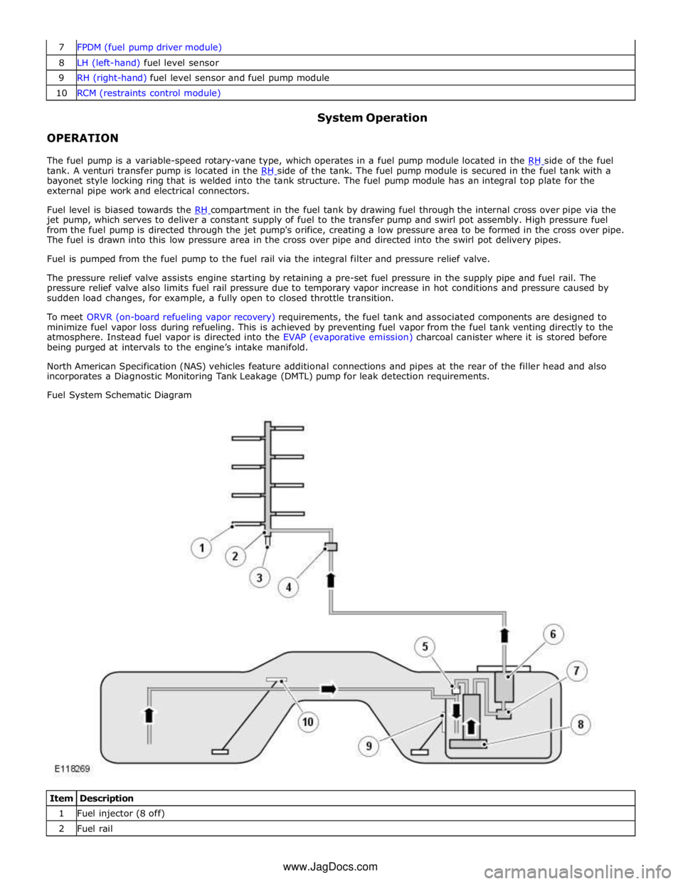
8 LH (left-hand) fuel level sensor 9 RH (right-hand) fuel level sensor and fuel pump module 10 RCM (restraints control module)
OPERATION System Operation
The fuel pump is a variable-speed rotary-vane type, which operates in a fuel pump module located in the RH side of the fuel tank. A venturi transfer pump is located in the RH side of the tank. The fuel pump module is secured in the fuel tank with a bayonet style locking ring that is welded into the tank structure. The fuel pump module has an integral top plate for the
external pipe work and electrical connectors.
Fuel level is biased towards the RH compartment in the fuel tank by drawing fuel through the internal cross over pipe via the jet pump, which serves to deliver a constant supply of fuel to the transfer pump and swirl pot assembly. High pressure fuel
from the fuel pump is directed through the jet pump's orifice, creating a low pressure area to be formed in the cross over pipe.
The fuel is drawn into this low pressure area in the cross over pipe and directed into the swirl pot delivery pipes.
Fuel is pumped from the fuel pump to the fuel rail via the integral filter and pressure relief valve.
The pressure relief valve assists engine starting by retaining a pre-set fuel pressure in the supply pipe and fuel rail. The
pressure relief valve also limits fuel rail pressure due to temporary vapor increase in hot conditions and pressure caused by
sudden load changes, for example, a fully open to closed throttle transition.
To meet ORVR (on-board refueling vapor recovery) requirements, the fuel tank and associated components are designed to
minimize fuel vapor loss during refueling. This is achieved by preventing fuel vapor from the fuel tank venting directly to the
atmosphere. Instead fuel vapor is directed into the EVAP (evaporative emission) charcoal canister where it is stored before
being purged at intervals to the engine’s intake manifold.
North American Specification (NAS) vehicles feature additional connections and pipes at the rear of the filler head and also
incorporates a Diagnostic Monitoring Tank Leakage (DMTL) pump for leak detection requirements.
Fuel System Schematic Diagram
Item Description 1 Fuel injector (8 off) 2 Fuel rail www.JagDocs.com
Page 1587 of 3039
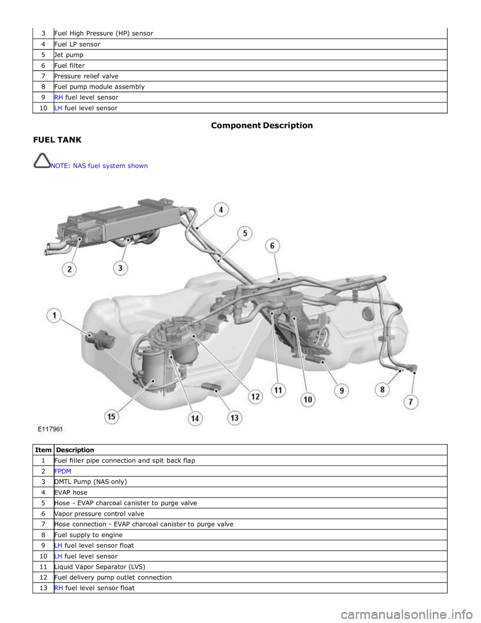
3 Fuel High Pressure (HP) sensor 4 Fuel LP sensor 5 Jet pump 6 Fuel filter 7 Pressure relief valve 8 Fuel pump module assembly 9 RH fuel level sensor 10 LH fuel level sensor
FUEL TANK
NOTE: NAS fuel system shown Component Description
Item Description 1 Fuel filler pipe connection and spit back flap 2 FPDM 3 DMTL Pump (NAS only) 4 EVAP hose 5 Hose - EVAP charcoal canister to purge valve 6 Vapor pressure control valve 7 Hose connection - EVAP charcoal canister to purge valve 8 Fuel supply to engine 9 LH fuel level sensor float 10 LH fuel level sensor 11 Liquid Vapor Separator (LVS) 12 Fuel delivery pump outlet connection 13 RH fuel level sensor float