JAGUAR XFR 2010 1.G Workshop Manual
XFR 2010 1.G
JAGUAR
JAGUAR
https://www.carmanualsonline.info/img/21/7642/w960_7642-0.png
JAGUAR XFR 2010 1.G Workshop Manual
Trending: clutch, b10eb, rear entertainment, coolant pump, Interior, bulb, coolant capacity
Page 661 of 3039
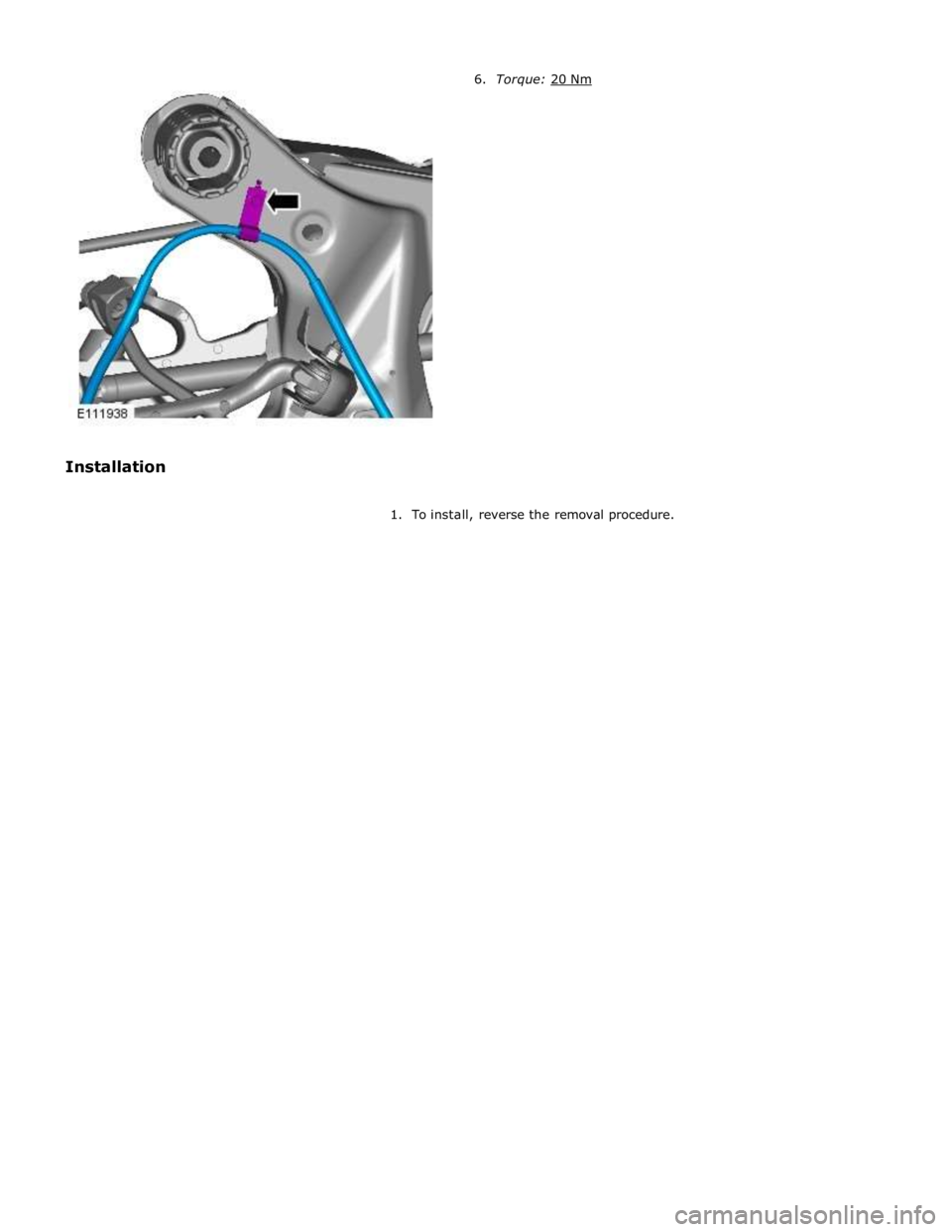
1. To install, reverse the removal procedure.
Page 662 of 3039
Parking Brake and Actuation - Parking Brake Module
Removal and Installation
Removal
NOTE: Removal steps in this procedure may contain installation details. Published: 11-May-2011
1. Refer to: Battery Disconnect and Connect (414-01 Battery, Mounting and Cables, General Procedures).
2. Refer to: Loadspace Trim Panel RH (501-05 Interior Trim and Ornamentation, Removal and Installation).
Installation
3. Torque: 4 Nm
1. To install, reverse the removal position
2. Configure the electronic parking brake (EPB) using the diagnostic tool.
Page 663 of 3039
Parking Brake and Actuation - Parking Brake Switch
Removal and Installation
Removal
NOTES: Published: 12-Jun-2013
The parking brake switch is part of the transmission control switch (TCS) assembly and therefore can not be serviced
separately.
Removal steps in this procedure may contain installation details.
1. Refer to: Battery Disconnect and Connect (414-01 Battery, Mounting and Cables, General Procedures).
2. Refer to: Transmission Control Switch (TCS) (307-05A Automatic Transmission/Transaxle External Controls - V6 3.0L Petrol, Removal and
Installation).
Installation
1. CAUTION: Make sure that all diagnostic trouble codes (DTCs) have
been removed after the road test.
To install, reverse the removal procedure.
Page 664 of 3039
Parking Brake and Actuation - Parking Brake Release Actuator
Removal and Installation
Removal Published: 06-May-2014
WARNING: Failure to release the tension and calibrate the electric parking brake during rear parking brake related service
procedures, could cause the parking brake to function incorrectly or become inoperative.
1. Refer to: Parking Brake Cable Tension Release (206-05 Parking Brake and Actuation, General Procedures).
2. WARNING: Make sure to support the vehicle with axle stands.
Raise and support the vehicle.
3. Remove the differential case.
Refer to: Differential Case - TDV6 3.0L Diesel /V8 5.0L Petrol/V8 S/C 5.0L Petrol (205-02 Rear Drive Axle/Differential, Removal and Installation).
Refer to: Differential Case - TD4 2.2L Diesel/TDV6 3.0L Diesel (205-02,
Removal and Installation).
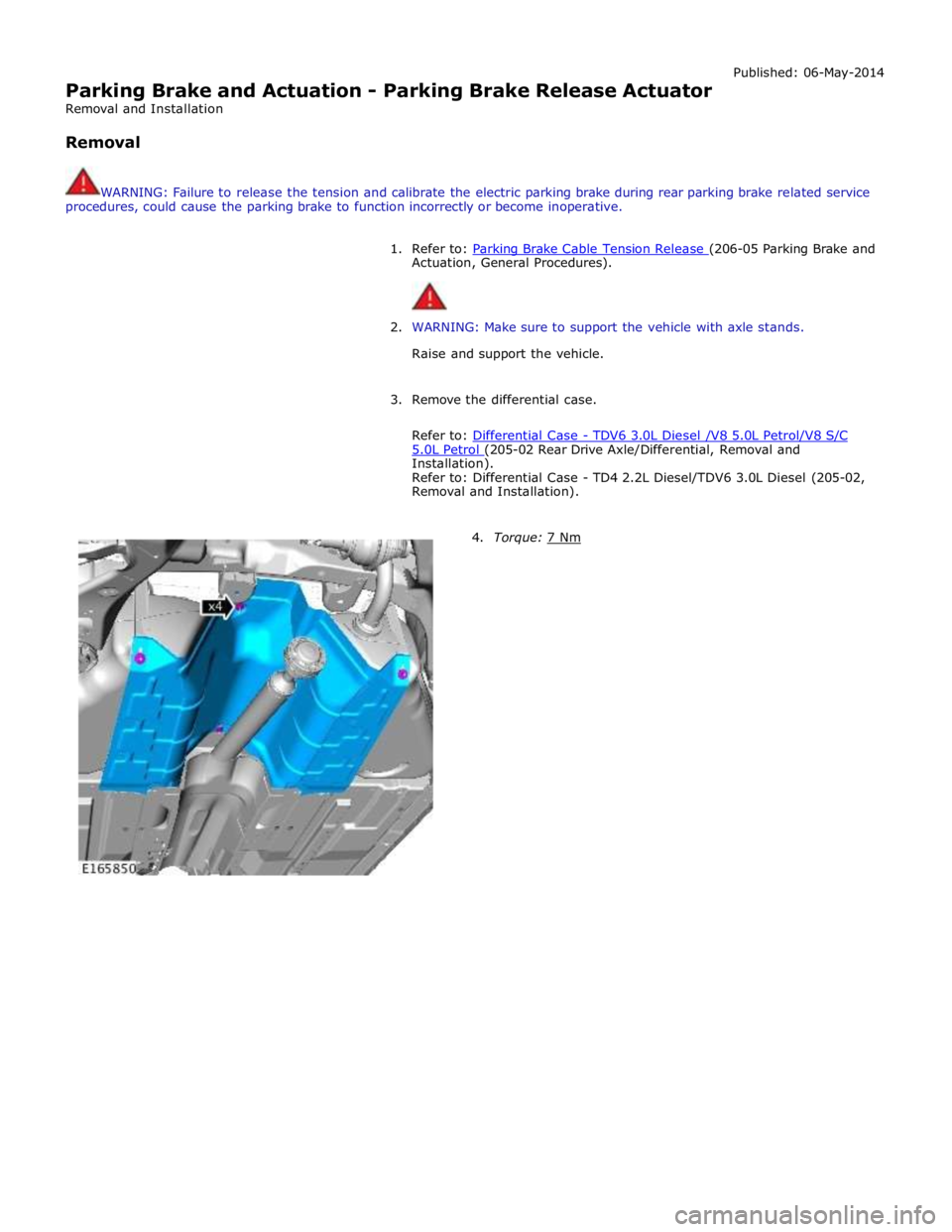
4. Torque: 7 Nm
Page 665 of 3039
Page 666 of 3039
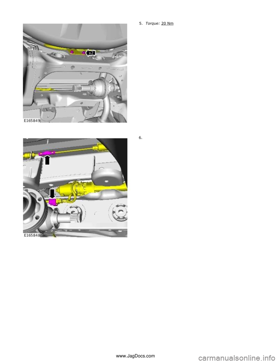
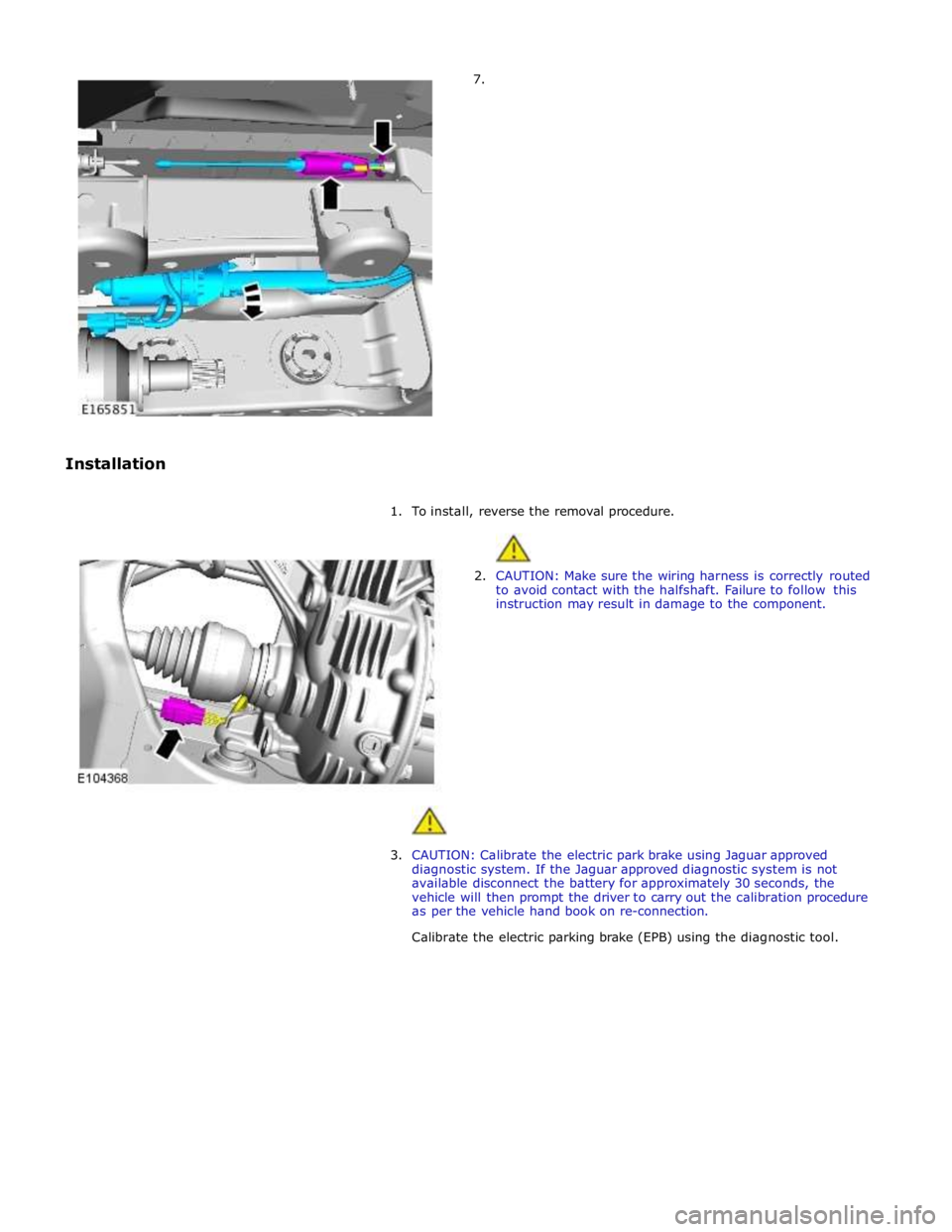
7.
Installation
1. To install, reverse the removal procedure.
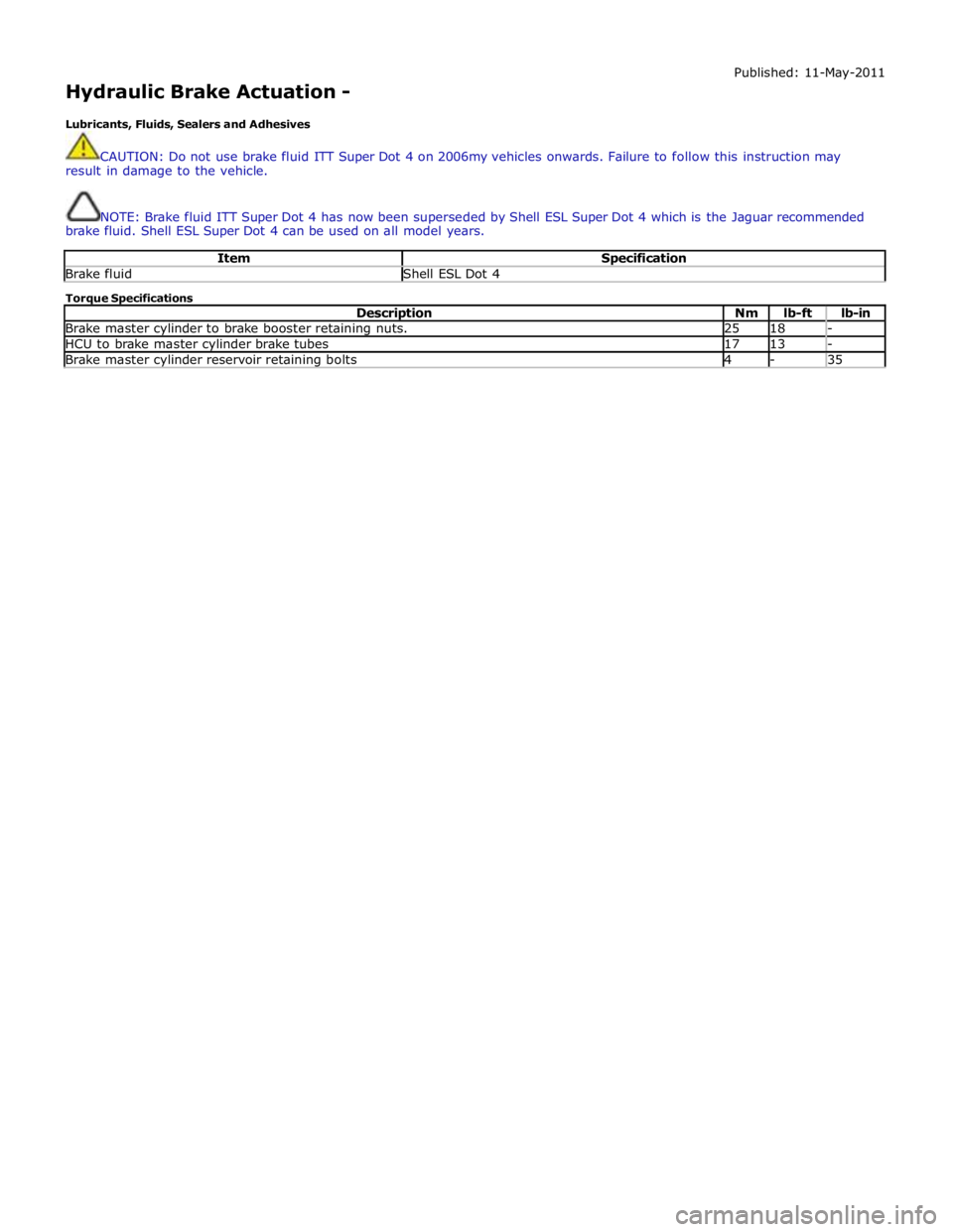
2. CAUTION: Make sure the wiring harness is correctly routed
to avoid contact with the halfshaft. Failure to follow this
instruction may result in damage to the component.
3. CAUTION: Calibrate the electric park brake using Jaguar approved
diagnostic system. If the Jaguar approved diagnostic system is not
available disconnect the battery for approximately 30 seconds, the
vehicle will then prompt the driver to carry out the calibration procedure
as per the vehicle hand book on re-connection.
Calibrate the electric parking brake (EPB) using the diagnostic tool.
Page 667 of 3039
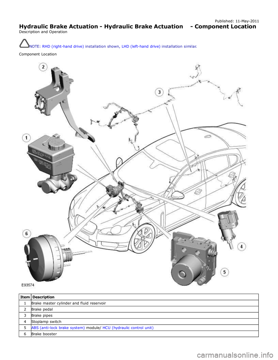
Hydraulic Brake Actuation -
Lubricants, Fluids, Sealers and Adhesives Published: 11-May-2011
CAUTION: Do not use brake fluid ITT Super Dot 4 on 2006my vehicles onwards. Failure to follow this instruction may
result in damage to the vehicle.
NOTE: Brake fluid ITT Super Dot 4 has now been superseded by Shell ESL Super Dot 4 which is the Jaguar recommended
brake fluid. Shell ESL Super Dot 4 can be used on all model years.
Item Specification Brake fluid Shell ESL Dot 4 Torque Specifications
Description Nm lb-ft lb-in Brake master cylinder to brake booster retaining nuts. 25 18 - HCU to brake master cylinder brake tubes 17 13 - Brake master cylinder reservoir retaining bolts 4 - 35
Page 668 of 3039
Published: 11-May-2011
Hydraulic Brake Actuation - Hydraulic Brake Actuation - Component Location
Description and Operation
NOTE: RHD (right-hand drive) installation shown, LHD (left-hand drive) installation similar.
Component Location
Item Description 1 Brake master cylinder and fluid reservoir 2 Brake pedal 3 Brake pipes 4 Stoplamp switch 5 ABS (anti-lock brake system) module/ HCU (hydraulic control unit) 6 Brake booster
Page 669 of 3039
Braided steel hoses are used to connect the brake pipes to the front and rear brake calipers.
Page 670 of 3039
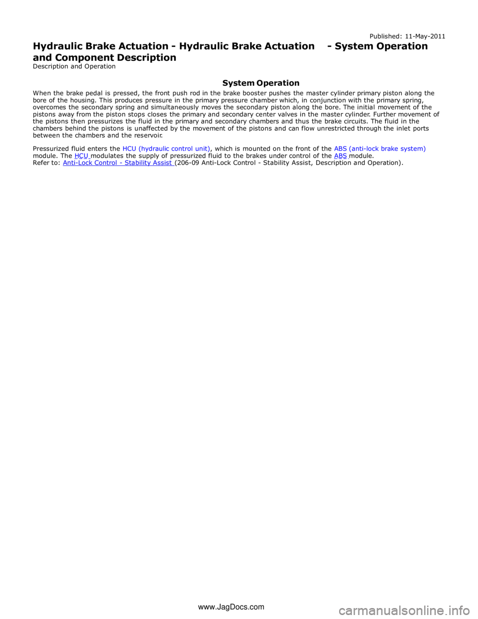
Refer to: Anti-Lock Control - Stability Assist (206-09 Anti-Lock Control - Stability Assist, Description and Operation). www.JagDocs.com
Trending: stop start, P0850, jump start terminals, Pump, C1A04, u3003-62, ect sensor electrical diagram
