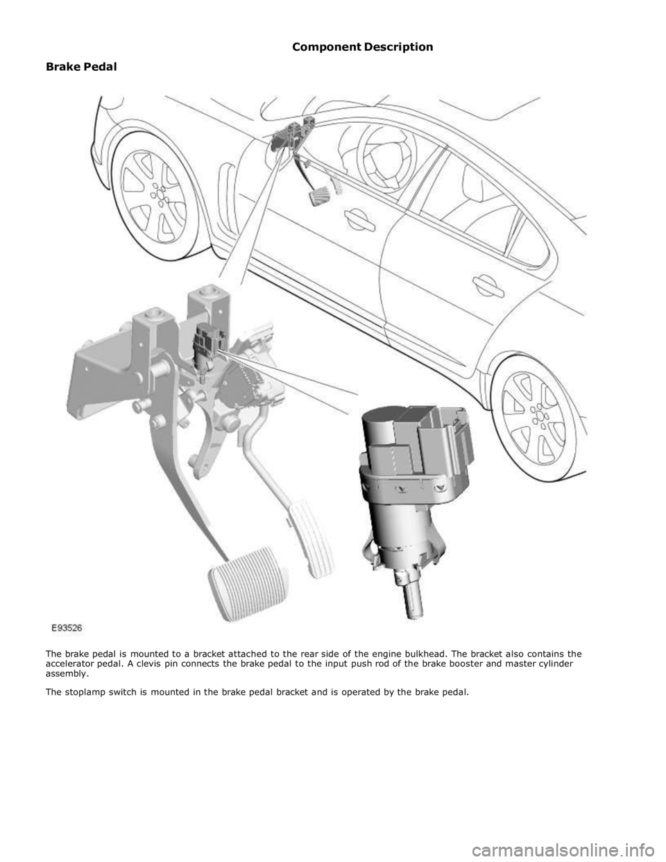
JAGUAR XFR 2010 1.G Workshop Manual
XFR 2010 1.G
JAGUAR
JAGUAR
https://www.carmanualsonline.info/img/21/7642/w960_7642-0.png
JAGUAR XFR 2010 1.G Workshop Manual
Trending: B100a 87, wiper fluid, catalytic converter, oil filler, C1a04-22, Cooling, B1c35
Page 671 of 3039
Page 672 of 3039
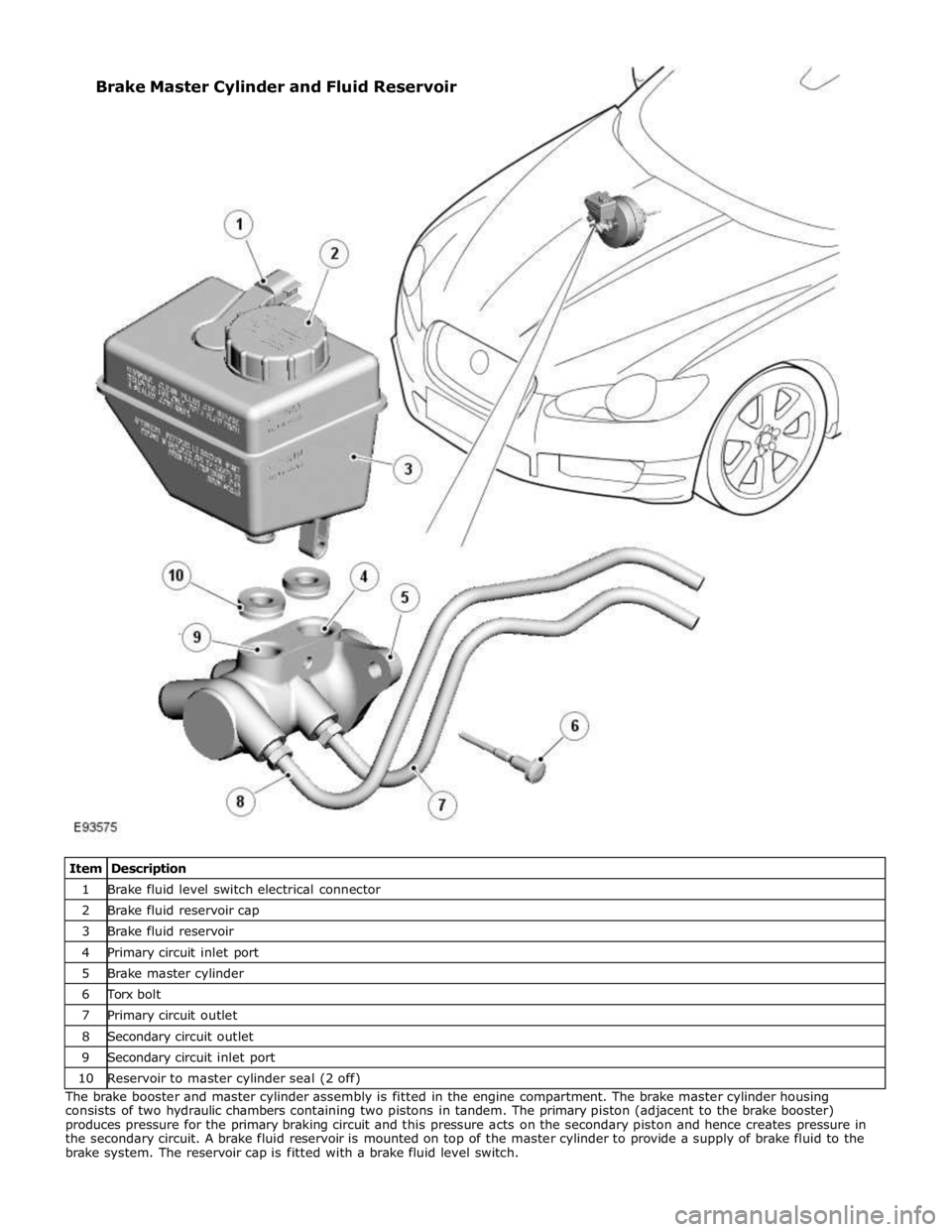
1 Brake fluid level switch electrical connector 2 Brake fluid reservoir cap 3 Brake fluid reservoir 4 Primary circuit inlet port 5 Brake master cylinder 6 Torx bolt 7 Primary circuit outlet 8 Secondary circuit outlet 9 Secondary circuit inlet port 10 Reservoir to master cylinder seal (2 off) The brake booster and master cylinder assembly is fitted in the engine compartment. The brake master cylinder housing
consists of two hydraulic chambers containing two pistons in tandem. The primary piston (adjacent to the brake booster)
produces pressure for the primary braking circuit and this pressure acts on the secondary piston and hence creates pressure in
the secondary circuit. A brake fluid reservoir is mounted on top of the master cylinder to provide a supply of brake fluid to the
brake system. The reservoir cap is fitted with a brake fluid level switch. Brake Master Cylinder and Fluid Reservoir
Page 673 of 3039
1 LH (left-hand) front brake 2 RH (right-hand) rear brake 3 LH rear brake 4 RH front brake 5 Primary circuit inlet port 6 Secondary circuit inlet port The ABS module is located in the passenger side, rear engine bay and incorporates the HCU. The HCU is a four channel unit that modulates the supply of hydraulic pressure to the brakes under control of the ABS module.
The primary and secondary outlets of the master cylinder are connected to the primary and secondary circuits within the HCU. The primary circuit in the HCU has separate outlet ports to the RH front and LH rear brakes. The secondary circuit in the HCU has separate outlet ports to the LH front and RH rear brakes.
Page 674 of 3039
CAUTION: The ABS module and the HCU are a single unit and must not be separated.
HCU Schematic Diagram
Item Description 1 Brake booster 2 Primary circuit 3 Secondary circuit 4 HCU
Page 675 of 3039
6 Pulsation damper 7 Separation valve 8 Damping chambers 9 Separation valve 10 Shuttle valve 11 Hydraulic pumps 12 Motor 13 Shuttle valve 14 Pressure sensor - all vehicles 15 Low pressure accumulator 16 Check valve 17 Low pressure accumulator 18 Inlet valve 19 Inlet valve 20 Inlet valve 21 Inlet valve 22 Outlet valve 23 Outlet valve 24 Outlet valve 25 Outlet valve 26 Pressure sensors - vehicles fitted with adaptive speed control only 27 RH front brake 28 LH rear brake 29 RH rear brake 30 LH front brake www.JagDocs.com
Page 676 of 3039
Page 677 of 3039
Hydraulic Brake Actuation - Brake Fluid Reservoir
Removal and Installation
Removal Published: 11-May-2011
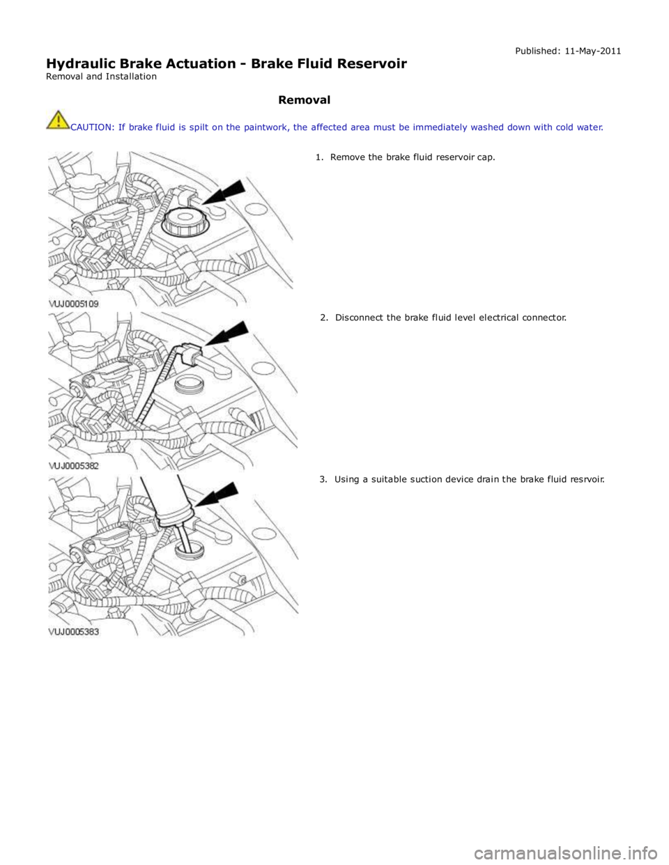
CAUTION: If brake fluid is spilt on the paintwork, the affected area must be immediately washed down with cold water.
1. Remove the brake fluid reservoir cap.
2. Disconnect the brake fluid level electrical connector.
3. Using a suitable suction device drain the brake fluid resrvoir.
Page 678 of 3039
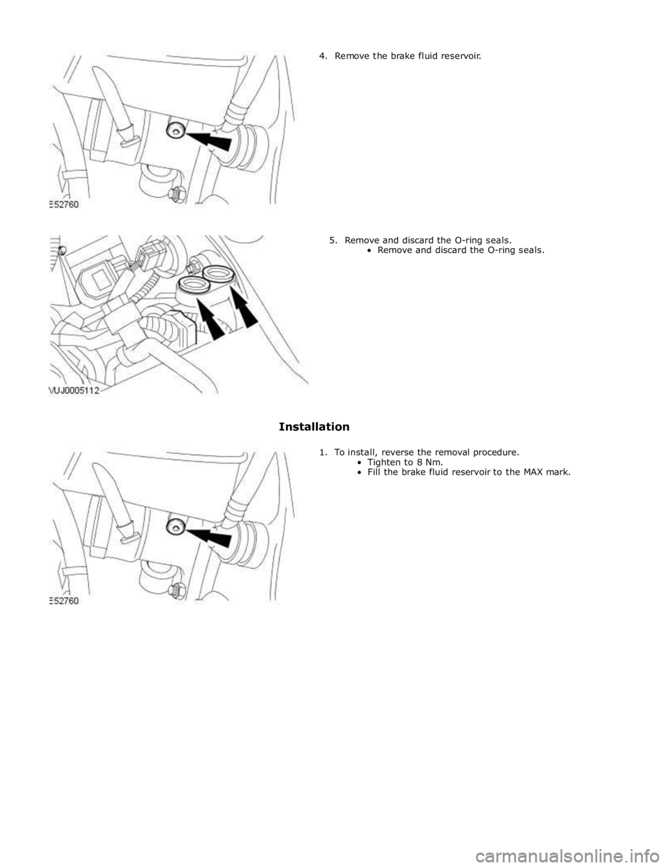
4. Remove the brake fluid reservoir.
5. Remove and discard the O-ring seals.
Remove and discard the O-ring seals.
Installation
1. To install, reverse the removal procedure.
Tighten to 8 Nm.
Fill the brake fluid reservoir to the MAX mark.
Page 679 of 3039
Hydraulic Brake Actuation - Brake Master Cylinder
Removal and Installation
Removal Published: 11-May-2011
1. WARNING: Make sure to support the vehicle with axle stands.
Raise and support the vehicle.
2. Remove the cowl vent screen.
For additional information, refer to: Cowl Vent Screen (501-02 Front End Body Panels, Removal and Installation).
3. CAUTION: Brake fluid will damage paint finished surfaces. If spilled,
immediately remove the fluid and clean the area with water.
Remove the brake fluid reservoir.
For additional information, refer to: Brake Fluid Reservoir (206-06 Hydraulic Brake Actuation, Removal and Installation).
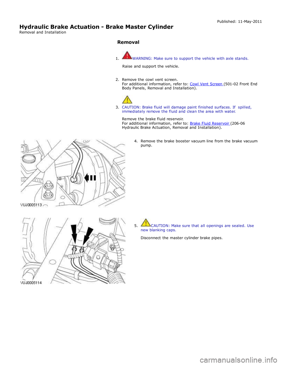
4. Remove the brake booster vacuum line from the brake vacuum
pump.
5. CAUTION: Make sure that all openings are sealed. Use
new blanking caps.
Disconnect the master cylinder brake pipes.
Page 680 of 3039
6. Release the fuse box.
7. Remove the brake master cylinder.
Installation
1. To install, reverse the removal procedure.
Install new O-ring seals. www.JagDocs.com
Trending: fog light, oil, U3000-54, Cylinder head, B1A54, Electrical relay, C1A58-68
