warning JAGUAR XFR 2010 1.G Manual Online
[x] Cancel search | Manufacturer: JAGUAR, Model Year: 2010, Model line: XFR, Model: JAGUAR XFR 2010 1.GPages: 3039, PDF Size: 58.49 MB
Page 539 of 3039
Rear Drive Axle/Differential - Differential Draining and Filling
General Procedures
Check Published: 11-May-2011
NOTE: Some variation in the illustrations may occur, but the essential information is always correct.
1. Refer to: Specifications - TDV6 3.0L Diesel /V8 5.0L Petrol/V8 S/C 5.0L Petrol (205-02 Rear Drive Axle/Differential, Specifications).
2. WARNING: Make sure to support the vehicle with axle stands.
Raise and support the vehicle.
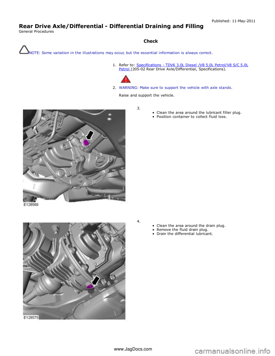
3.
Clean the area around the lubricant filler plug.
Position container to collect fluid loss.
4.
Clean the area around the drain plug.
Remove the fluid drain plug.
Drain the differential lubricant. www.JagDocs.com
Page 542 of 3039
Published: 11-May-2011
Rear Drive Axle/Differential - Differential Case TDV6 3.0L Diesel /V8 5.0L
Petrol/V8 S/C 5.0L Petrol
Removal and Installation
Removal
All vehicles
1. WARNING: Do not work on or under a vehicle supported only by a
jack. Always support the vehicle on safety stands.
Raise and support the vehicle.
2. Refer to: Rear Halfshaft - TDV6 3.0L Diesel /V8 5.0L Petrol/V8 S/C 5.0L Petrol (205-05 Rear Drive Halfshafts, Removal and Installation).
3. Refer to: Exhaust System (309-00C Exhaust System - V8 5.0L Petrol/V8 S/C 5.0L Petrol, Removal and Installation).
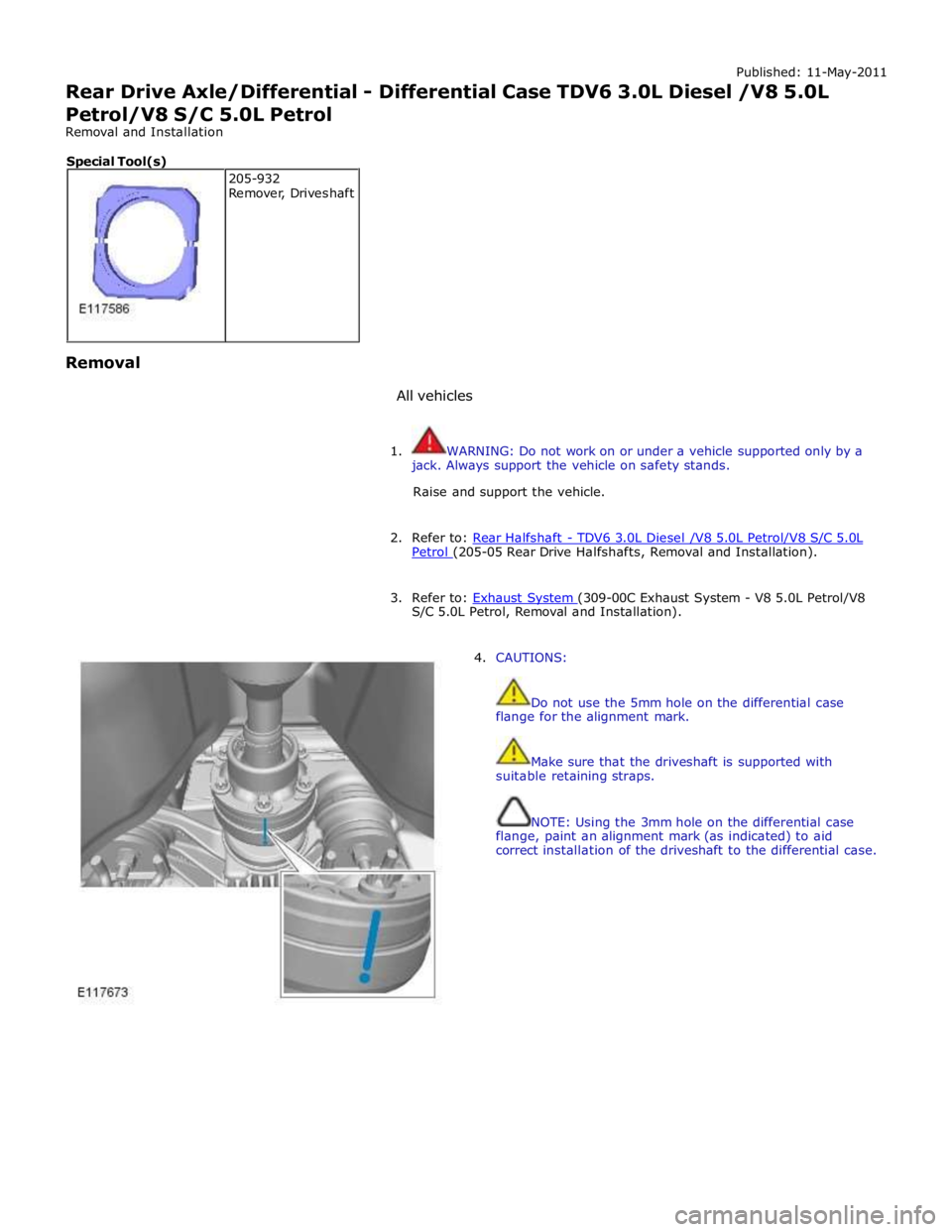
4. CAUTIONS:
Do not use the 5mm hole on the differential case
flange for the alignment mark.
Make sure that the driveshaft is supported with
suitable retaining straps.
NOTE: Using the 3mm hole on the differential case
flange, paint an alignment mark (as indicated) to aid
correct installation of the driveshaft to the differential case. 205-932
Remover, Driveshaft Special Tool(s)
Page 547 of 3039
Published: 11-May-2011
Rear Drive Axle/Differential - Differential Front Bushing TDV6 3.0L Diesel /V8 5.0L Petrol/V8 S/C 5.0L Petrol
Removal and Installation
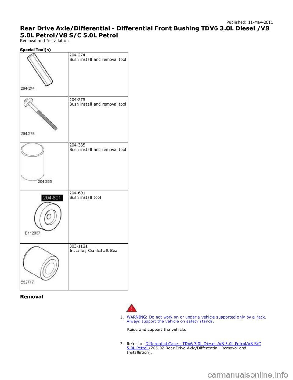
Special Tool(s)
204-274
Bush install and removal tool
204-275
Bush install and removal tool
204-335
Bush install and removal tool
204-601
Bush install tool
303-1121
Installer, Crankshaft Seal Removal
1. WARNING: Do not work on or under a vehicle supported only by a jack.
Always support the vehicle on safety stands.
Raise and support the vehicle.
2. Refer to: Differential Case - TDV6 3.0L Diesel /V8 5.0L Petrol/V8 S/C 5.0L Petrol (205-02 Rear Drive Axle/Differential, Removal and Installation).
Page 550 of 3039
Removal
1. WARNING: Do not work on or under a vehicle supported only by a jack.
Always support the vehicle on safety stands.
Raise and support the vehicle.
2. Refer to: Driveshaft - TD4 2.2L Diesel (205-01, Removal and
Installation).
Refer to: Driveshaft - V6 3.0L Petrol (205-01 Driveshaft, Removal and Installation).
Refer to: Driveshaft - V8 5.0L Petrol/V8 S/C 5.0L Petrol (205-01 Driveshaft, Removal and Installation).
Refer to: Driveshaft - TDV6 3.0L Diesel (205-01 Driveshaft, Removal and Installation).
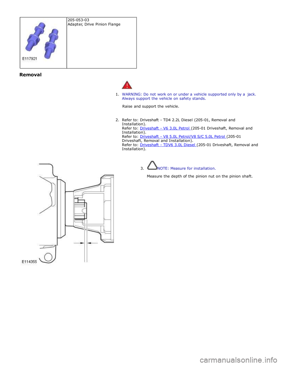
3. NOTE: Measure for installation.
Measure the depth of the pinion nut on the pinion shaft. 205-053-03
Adapter, Drive Pinion Flange
Page 566 of 3039
Removal
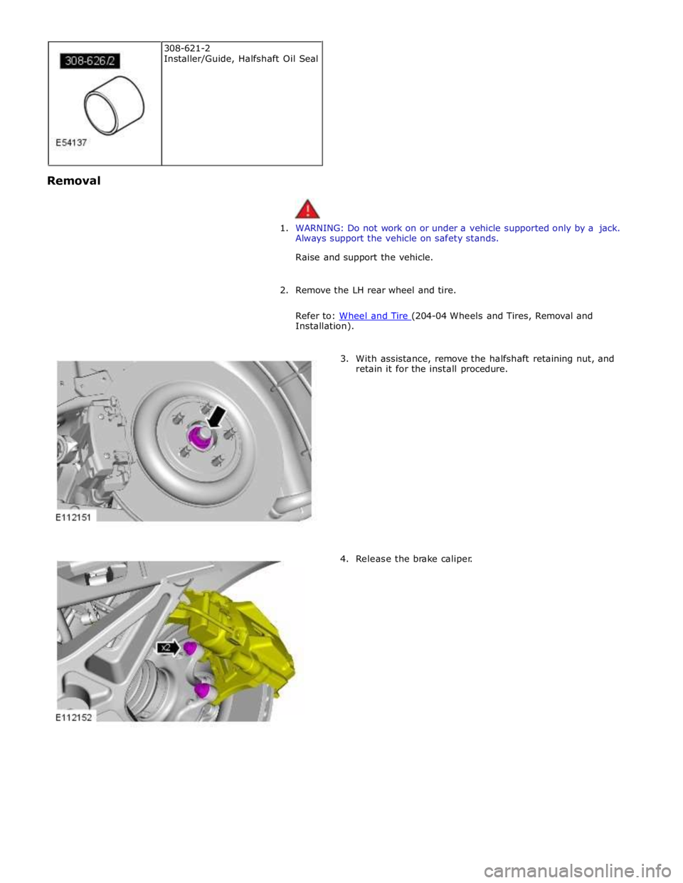
1. WARNING: Do not work on or under a vehicle supported only by a jack.
Always support the vehicle on safety stands.
Raise and support the vehicle.
2. Remove the LH rear wheel and tire.
Refer to: Wheel and Tire (204-04 Wheels and Tires, Removal and Installation).
3. With assistance, remove the halfshaft retaining nut, and
retain it for the install procedure.
4. Release the brake caliper. 308-621-2
Installer/Guide, Halfshaft Oil Seal
Page 575 of 3039
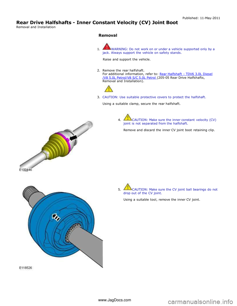
Rear Drive Halfshafts - Inner Constant Velocity (CV) Joint Boot
Removal and Installation
Removal Published: 11-May-2011
1. WARNING: Do not work on or under a vehicle supported only by a
jack. Always support the vehicle on safety stands.
Raise and support the vehicle.
2. Remove the rear halfshaft.
For additional information, refer to: Rear Halfshaft - TDV6 3.0L Diesel /V8 5.0L Petrol/V8 S/C 5.0L Petrol (205-05 Rear Drive Halfshafts, Removal and Installation).
3. CAUTION: Use suitable protective covers to protect the halfshaft.
Using a suitable clamp, secure the rear halfshaft.
4. CAUTION: Make sure the inner constant velocity (CV)
joint is not separated from the halfshaft.
Remove and discard the inner CV joint boot retaining clip.
5. CAUTION: Make sure the CV joint ball bearings do not
drop out of the CV joint.
Using a suitable tool, remove the inner CV joint. www.JagDocs.com
Page 579 of 3039
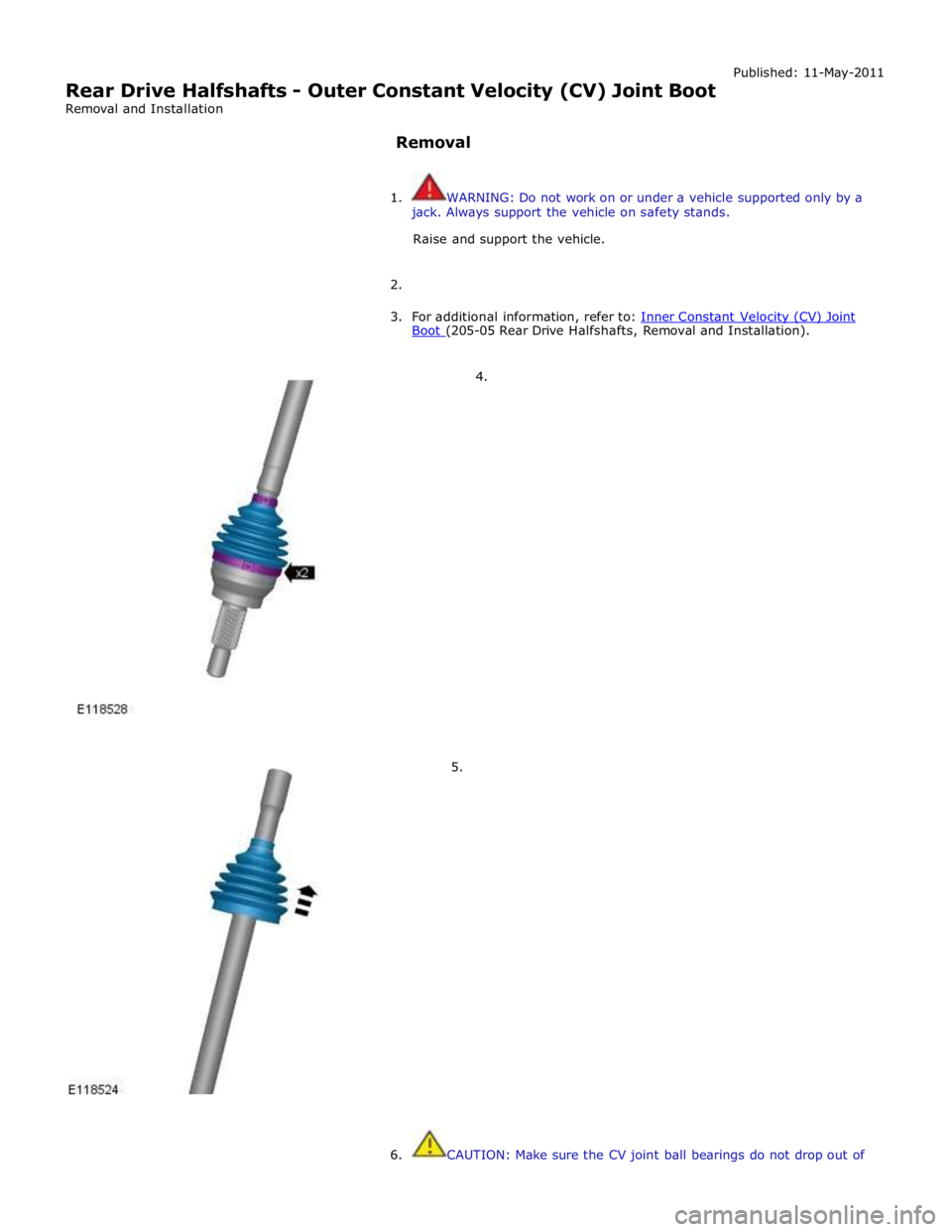
Rear Drive Halfshafts - Outer Constant Velocity (CV) Joint Boot
Removal and Installation
Removal Published: 11-May-2011
1. WARNING: Do not work on or under a vehicle supported only by a
jack. Always support the vehicle on safety stands.
Raise and support the vehicle.
2.
3. For additional information, refer to: Inner Constant Velocity (CV) Joint Boot (205-05 Rear Drive Halfshafts, Removal and Installation).
4.
5.
6. CAUTION: Make sure the CV joint ball bearings do not drop out of
Page 583 of 3039
If the concern becomes evident during this check, verify it fits the description given before the road test. If the concern is not
evident, attempt to duplicate the condition using the information from the description.
If a concern exists, use the Symptom Chart in order to isolate it to a specific sub-system and condition description. From this
description, a list of possible sources can be used to further narrow the cause to a specific component or condition.
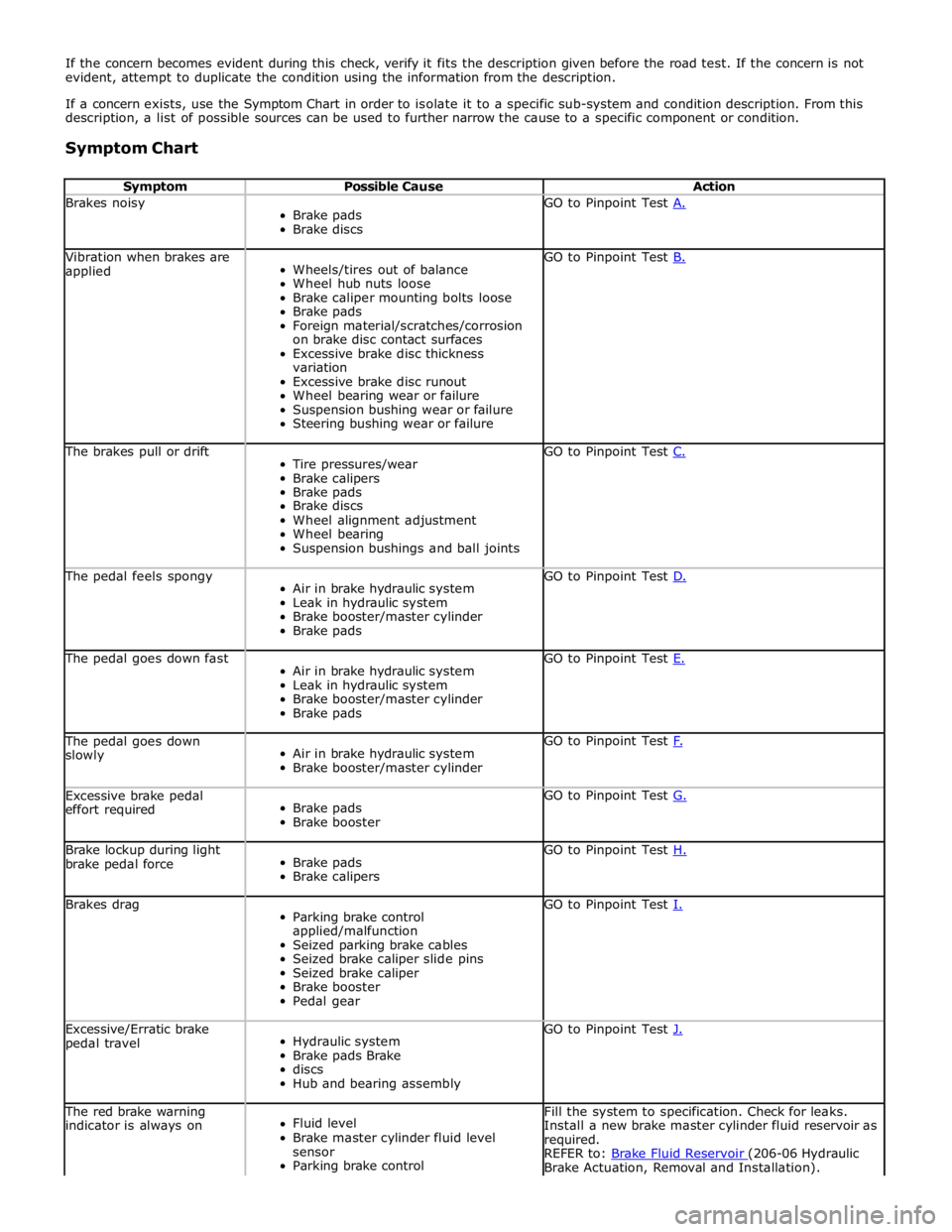
Symptom Chart
Symptom Possible Cause Action Brakes noisy
Brake pads
Brake discs GO to Pinpoint Test A. Vibration when brakes are
applied
Wheels/tires out of balance
Wheel hub nuts loose
Brake caliper mounting bolts loose
Brake pads
Foreign material/scratches/corrosion
on brake disc contact surfaces
Excessive brake disc thickness
variation
Excessive brake disc runout
Wheel bearing wear or failure
Suspension bushing wear or failure
Steering bushing wear or failure GO to Pinpoint Test B. The brakes pull or drift
Tire pressures/wear
Brake calipers
Brake pads
Brake discs
Wheel alignment adjustment
Wheel bearing
Suspension bushings and ball joints GO to Pinpoint Test C. The pedal feels spongy
Air in brake hydraulic system
Leak in hydraulic system
Brake booster/master cylinder
Brake pads GO to Pinpoint Test D. The pedal goes down fast
Air in brake hydraulic system
Leak in hydraulic system
Brake booster/master cylinder
Brake pads GO to Pinpoint Test E. The pedal goes down
slowly
Air in brake hydraulic system
Brake booster/master cylinder GO to Pinpoint Test F. Excessive brake pedal
effort required
Brake pads
Brake booster GO to Pinpoint Test G. Brake lockup during light
brake pedal force
Brake pads
Brake calipers GO to Pinpoint Test H. Brakes drag
Parking brake control
applied/malfunction
Seized parking brake cables
Seized brake caliper slide pins
Seized brake caliper
Brake booster
Pedal gear GO to Pinpoint Test I. Excessive/Erratic brake
pedal travel
Hydraulic system
Brake pads Brake
discs
Hub and bearing assembly GO to Pinpoint Test J. The red brake warning
indicator is always on
Fluid level
Brake master cylinder fluid level
sensor
Parking brake control Fill the system to specification. Check for leaks.
Install a new brake master cylinder fluid reservoir as
required.
REFER to: Brake Fluid Reservoir (206-06 Hydraulic Brake Actuation, Removal and Installation).
Page 590 of 3039
Does the brake pedal return to its original position? Yes
No action required, vehicle is OK.
No
GO to K2. K2: CHECK FOR BRAKE PEDAL BINDING 1 Disconnect the brake booster from the brake pedal. Check the brake pedal to ensure free operation. Is the brake pedal operating freely? Yes
Install a new brake booster as required. REFER to:
Brake Booster (206-07 Power Brake Actuation, Removal and Installation), Brake Booster - RHD (206-07, Removal and Installation).
Re-test the system for normal operation.
No
Repair or install new brake pedal. Re-test the system for normal operation. Component Tests
Brake Booster
1. Check all hoses and connections. All unused vacuum connectors should be capped. Hoses and their connections should
be correctly secured and in good condition with no holes and no collapsed areas. Inspect the valve on the brake booster
for damage.
2. Check the hydraulic brake system for leaks or low fluid.
3. With the automatic transmission in PARK, stop the engine and apply the parking brake. Pump the brake pedal several
times to exhaust all vacuum in the system. With the engine switched off and all vacuum in the system exhausted,
apply the brake pedal and hold it down. Start the engine. If the vacuum system is operating, the brake pedal will tend
to move downward under constant foot pressure. If no motion is felt, the vacuum booster system is not functioning.
4. Remove the vacuum hose from the brake booster. Manifold vacuum should be available at the brake booster end of the
hose with the engine at idle speed and the automatic transmission in PARK. Make sure that all unused vacuum outlets
are correctly capped, hose connectors are correctly secured and vacuum hoses are in good condition. When it is
established that manifold vacuum is available to the brake booster, connect the vacuum hose to the brake booster and
repeat Step 3. If no downward movement of the brake pedal is felt, install a new brake booster.
5. Operate the engine for a minimum of 10 seconds at a fast idle. Stop the engine and allow the vehicle to stand for 10
minutes. Then, apply the brake pedal with approximately 89 N (20lb) of force. The pedal feel (brake application) should
be the same as that noted with the engine running. If the brake pedal feels hard (no power assist), install a new valve
and then repeat the test. If the brake pedal still feels hard, install a new brake booster. If the brake pedal movement
feels spongy, bleed the brake system.
REFER to: Brake System Bleeding (206-00 Brake System - General Information, General Procedures). Brake Master Cylinder
Usually, the first and strongest indicator of anything wrong in the brake system is a feeling through the brake pedal. In
diagnosing the condition of the brake master cylinder, check pedal feel as evidence of a brake concern. Check for brake warning
lamp illumination and the brake fluid level in the brake master cylinder reservoir.
Normal Conditions
The following conditions are considered normal and are not indications that the brake master cylinder is in need of repair.
Modern brake systems are designed to produce a pedal effort that is not as hard as in the past. Complaints of light
pedal efforts should be compared to the pedal efforts of another vehicle of the same model and year.
The fluid level will fall with brake pad wear.
Abnormal Conditions
Changes in the brake pedal feel or brake pedal travel are indicators that something could be wrong in the brake system. The
diagnostic procedure and techniques use brake pedal feel, warning indicator illumination and low brake fluid level as indicators
to diagnosing brake system concerns. The following conditions are considered abnormal and indicate that the brake master
cylinder is in need of repair:
NOTE: Prior to carrying out any diagnosis, make sure the brake system warning indicator is functional.
Brake pedal goes down fast. This could be caused by an external or internal leak.
Brake pedal goes down slowly. This could be caused by an internal or external leak.
Brake pedal is low or feels spongy. This condition may be caused by no fluid in the brake master cylinder, reservoir cap
vent holes clogged or air in the hydraulic system.
Brake pedal effort is excessive. This may be caused by a bind or obstruction in the pedal/linkage, a faulty non-return
valve, booster or insufficient booster vacuum.
Rear brakes lock up during light pedal force. This may be caused by damaged brake pads, a partially applied parking
brake, a damaged ABS sensor or bearing failure.
Brake pedal effort erratic. This condition could be caused by the brake booster or incorrectly installed brake pads.
Brake warning indicator is on. This may be caused by low fluid level or float assembly damaged. www.JagDocs.com
Page 594 of 3039
Brake System - General Information - Brake System Bleeding
General Procedures
CAUTIONS:
The brake fluid reservoir must remain full with new, clean brake fluid at all times during bleeding. Published: 11-May-2011
Brake fluid will damage paint finished surfaces. If spilled, immediately remove the fluid and clean the area with water.
NOTE:
All vehicles
1. WARNING: Do not work on or under a vehicle supported only by a
jack. Always support the vehicle on safety stands.
Raise and support the vehicle.
2. Check that the brake fluid lines are secure and that there are no signs of
a brake fluid leak. If a brake fluid leak is detected, investigate and
rectify the cause of the leak before bleeding the brakes.
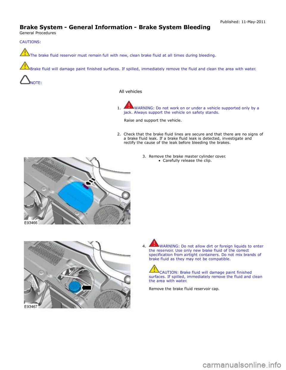
3. Remove the brake master cylinder cover.
Carefully release the clip.
4. WARNING: Do not allow dirt or foreign liquids to enter
the reservoir. Use only new brake fluid of the correct
specification from airtight containers. Do not mix brands of
brake fluid as they may not be compatible.
CAUTION: Brake fluid will damage paint finished
surfaces. If spilled, immediately remove the fluid and clean
the area with water.
Remove the brake fluid reservoir cap.