warning JAGUAR XFR 2010 1.G Repair Manual
[x] Cancel search | Manufacturer: JAGUAR, Model Year: 2010, Model line: XFR, Model: JAGUAR XFR 2010 1.GPages: 3039, PDF Size: 58.49 MB
Page 376 of 3039
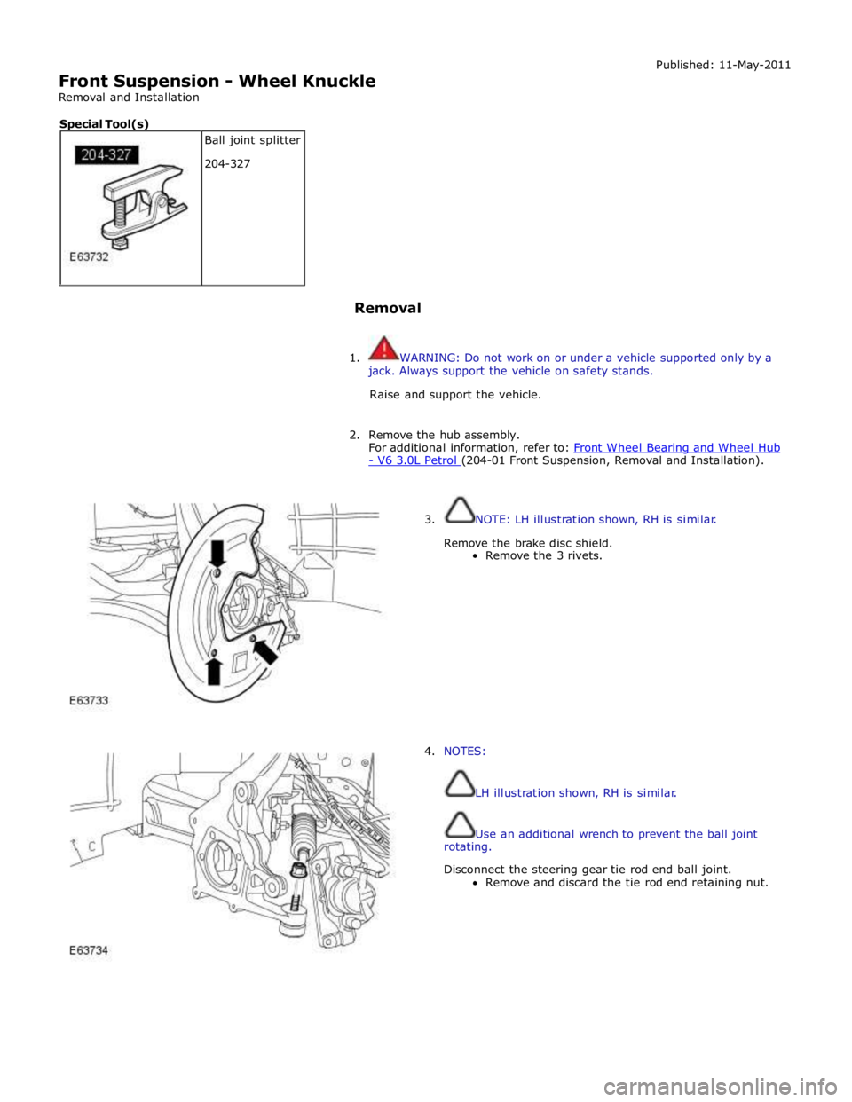
Front Suspension - Wheel Knuckle
Removal and Installation Published: 11-May-2011
Removal
1. WARNING: Do not work on or under a vehicle supported only by a
jack. Always support the vehicle on safety stands.
Raise and support the vehicle.
2. Remove the hub assembly.
For additional information, refer to: Front Wheel Bearing and Wheel Hub - V6 3.0L Petrol (204-01 Front Suspension, Removal and Installation).
3. NOTE: LH illustration shown, RH is similar.
Remove the brake disc shield.
Remove the 3 rivets.
4. NOTES:
LH illustration shown, RH is similar.
Use an additional wrench to prevent the ball joint
rotating.
Disconnect the steering gear tie rod end ball joint.
Remove and discard the tie rod end retaining nut. Ball joint splitter
204-327 Special Tool(s)
Page 399 of 3039
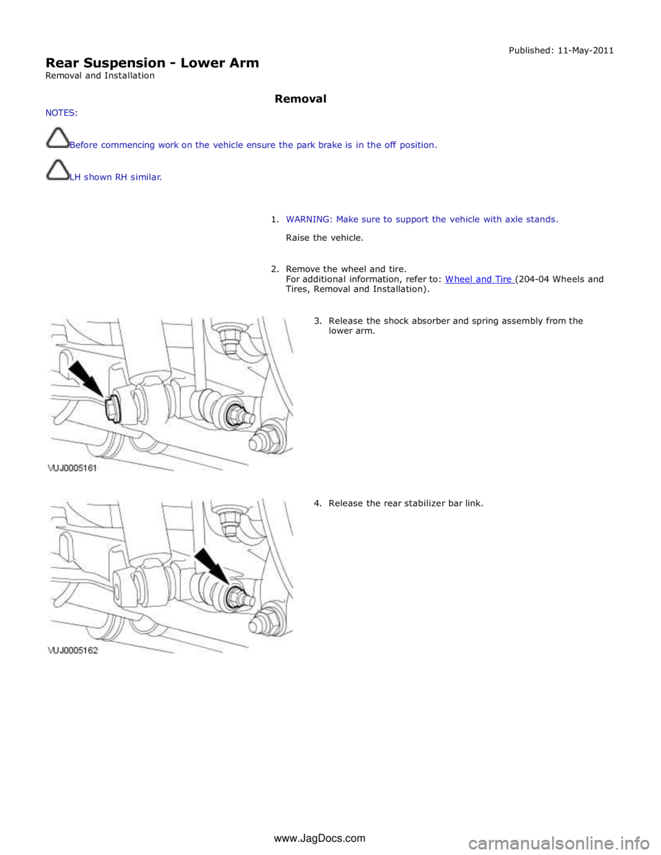
Rear Suspension - Lower Arm
Removal and Installation Published: 11-May-2011
NOTES: Removal
Before commencing work on the vehicle ensure the park brake is in the off position.
LH shown RH similar.
1. WARNING: Make sure to support the vehicle with axle stands.
Raise the vehicle.
2. Remove the wheel and tire.
For additional information, refer to: W heel and Tire (204-04 Wheels and Tires, Removal and Installation).
3. Release the shock absorber and spring assembly from the
lower arm.
4. Release the rear stabilizer bar link. www.JagDocs.com
Page 403 of 3039
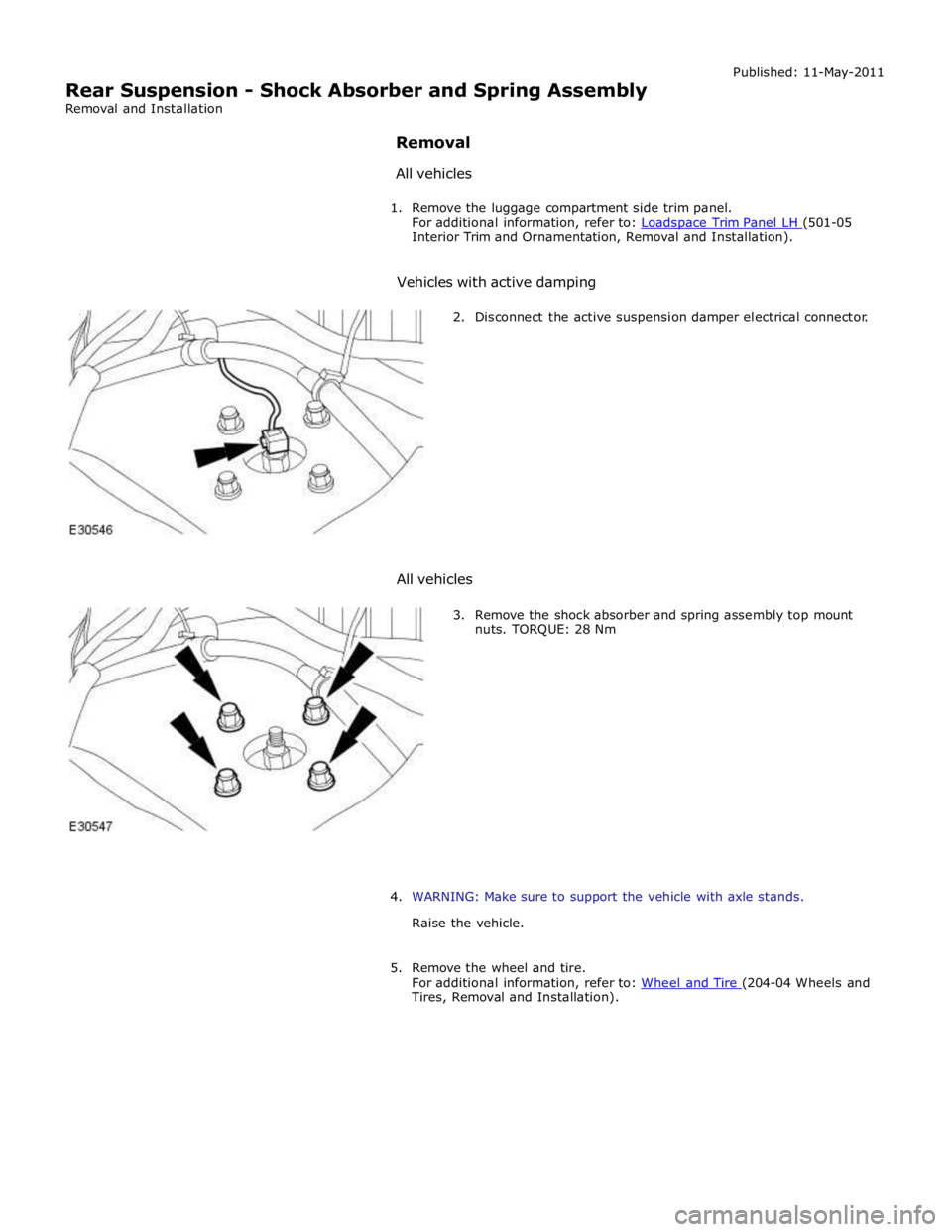
Interior Trim and Ornamentation, Removal and Installation).
Vehicles with active damping
2. Disconnect the active suspension damper electrical connector.
All vehicles
3. Remove the shock absorber and spring assembly top mount
nuts. TORQUE: 28 Nm
4. WARNING: Make sure to support the vehicle with axle stands.
Raise the vehicle.
5. Remove the wheel and tire.
For additional information, refer to: Wheel and Tire (204-04 Wheels and Tires, Removal and Installation).
Page 404 of 3039
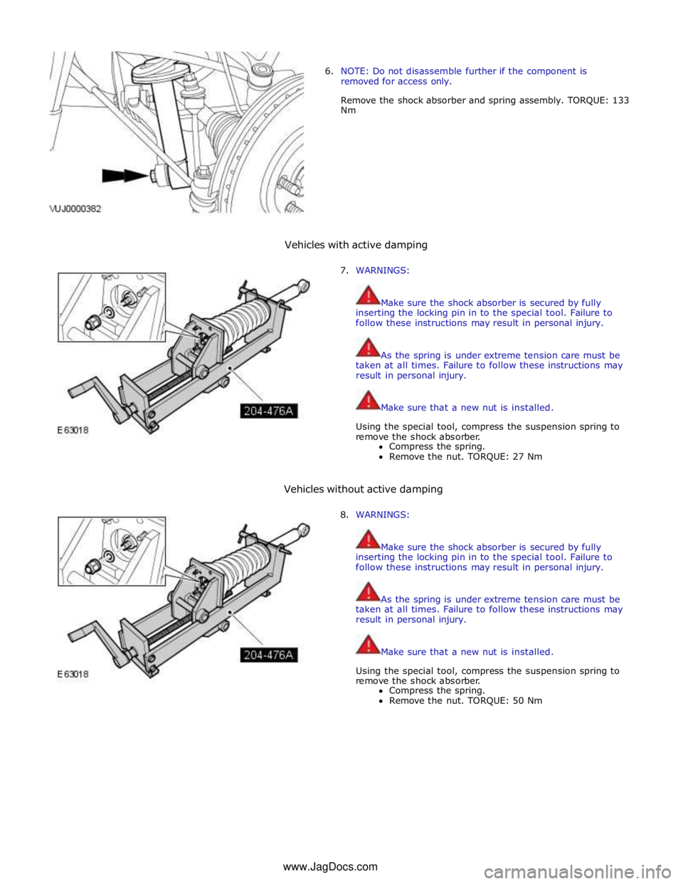
6. NOTE: Do not disassemble further if the component is
removed for access only.
Remove the shock absorber and spring assembly. TORQUE: 133
Nm
Vehicles with active damping
7. WARNINGS:
Make sure the shock absorber is secured by fully
inserting the locking pin in to the special tool. Failure to
follow these instructions may result in personal injury.
As the spring is under extreme tension care must be
taken at all times. Failure to follow these instructions may
result in personal injury.
Make sure that a new nut is installed.
Using the special tool, compress the suspension spring to
remove the shock absorber.
Compress the spring.
Remove the nut. TORQUE: 27 Nm
Vehicles without active damping
8. WARNINGS:
Make sure the shock absorber is secured by fully
inserting the locking pin in to the special tool. Failure to
follow these instructions may result in personal injury.
As the spring is under extreme tension care must be
taken at all times. Failure to follow these instructions may
result in personal injury.
Make sure that a new nut is installed.
Using the special tool, compress the suspension spring to
remove the shock absorber.
Compress the spring.
Remove the nut. TORQUE: 50 Nm
www.JagDocs.com
Page 406 of 3039
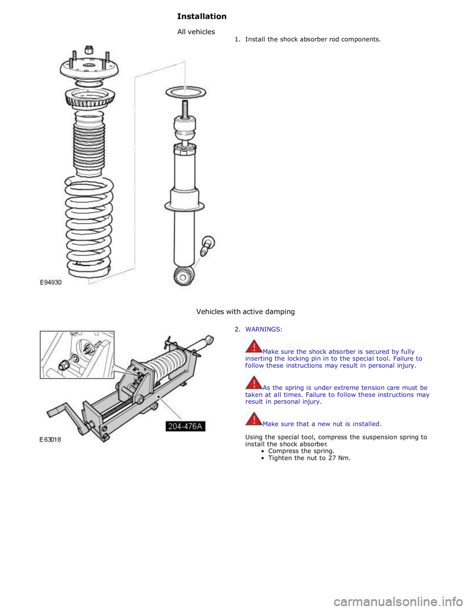
1. Install the shock absorber rod components.
Vehicles with active damping
2. WARNINGS:
Make sure the shock absorber is secured by fully
inserting the locking pin in to the special tool. Failure to
follow these instructions may result in personal injury.
As the spring is under extreme tension care must be
taken at all times. Failure to follow these instructions may
result in personal injury.
Make sure that a new nut is installed.
Using the special tool, compress the suspension spring to
install the shock absorber.
Compress the spring.
Tighten the nut to 27 Nm.
Installation
Allvehicles
Page 407 of 3039
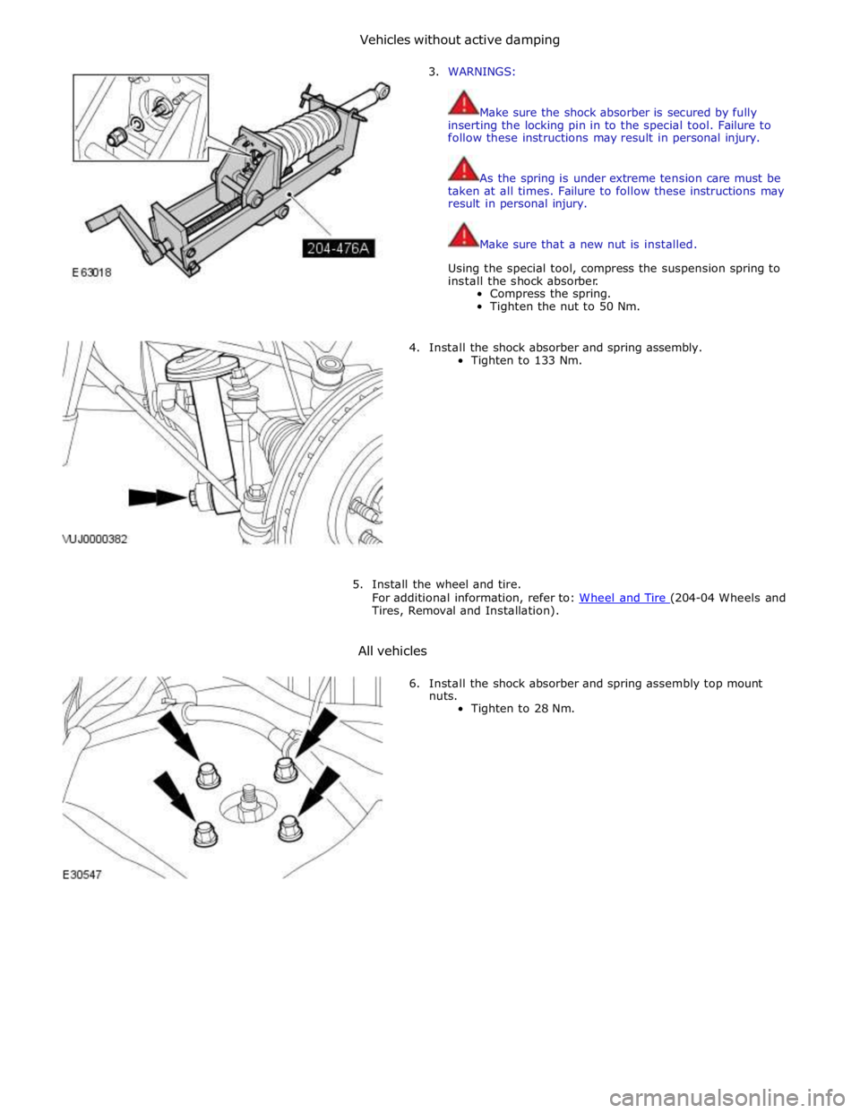
3. WARNINGS:
Make sure the shock absorber is secured by fully
inserting the locking pin in to the special tool. Failure to
follow these instructions may result in personal injury.
As the spring is under extreme tension care must be
taken at all times. Failure to follow these instructions may
result in personal injury.
Make sure that a new nut is installed.
Using the special tool, compress the suspension spring to
install the shock absorber.
Compress the spring.
Tighten the nut to 50 Nm.
4. Install the shock absorber and spring assembly.
Tighten to 133 Nm.
5. Install the wheel and tire.
For additional information, refer to: Wheel and Tire (204-04 Wheels and Tires, Removal and Installation).
All vehicles
6. Install the shock absorber and spring assembly top mount
nuts.
Tighten to 28 Nm.
Vehicleswithoutactivedamping
Page 409 of 3039
Rear Suspension - Shock Absorber Lower Bushing
Removal and Installation
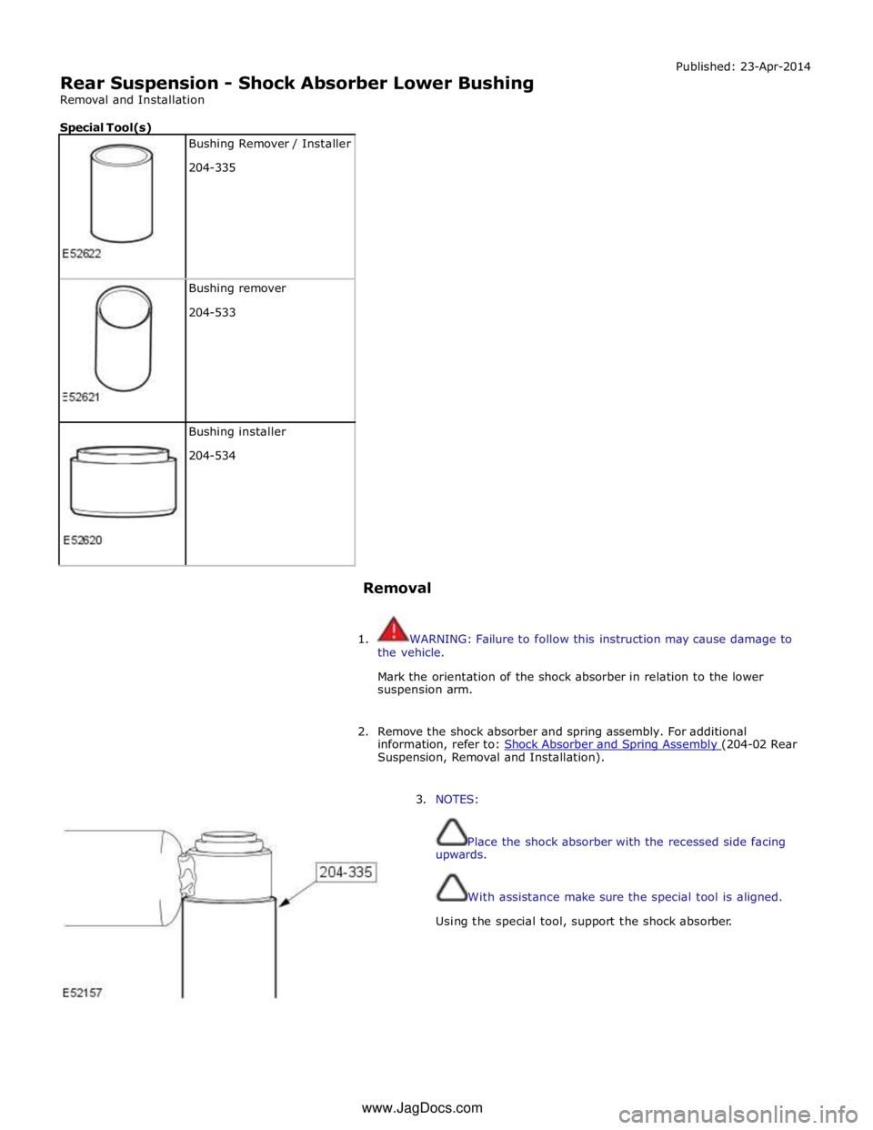
Special Tool(s)
Bushing Remover / Installer
204-335
Bushing remover
204-533
Bushing installer
204-534
Removal Published: 23-Apr-2014
1. WARNING: Failure to follow this instruction may cause damage to
the vehicle.
Mark the orientation of the shock absorber in relation to the lower
suspension arm.
2. Remove the shock absorber and spring assembly. For additional
information, refer to: Shock Absorber and Spring Assembly (204-02 Rear Suspension, Removal and Installation).
3. NOTES:
Place the shock absorber with the recessed side facing
upwards.
With assistance make sure the special tool is aligned.
Using the special tool, support the shock absorber. www.JagDocs.com
Page 410 of 3039
4. NOTES:
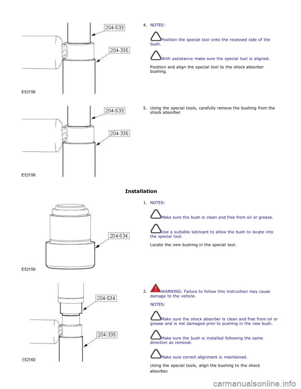
bush. Position the special tool onto the recessed side of the
With assistance make sure the special tool is aligned.
Position and align the special tool to the shock absorber
bushing.
5. Using the special tools, carefully remove the bushing from the
shock absorber.
Installation
1. NOTES:
Make sure the bush is clean and free from oil or grease.
Use a suitable lubricant to allow the bush to locate into
the special tool.
Locate the new bushing in the special tool.
2. WARNING: Failure to follow this instruction may cause
damage to the vehicle.
NOTES:
Make sure the shock absorber is clean and free from oil or
grease and is not damaged prior to pushing in the new bush.
Make sure the bush is installed following the same
direction as removal.
Make sure correct alignment is maintained.
Using the special tools, align the bushing to the shock absorber.
Page 412 of 3039
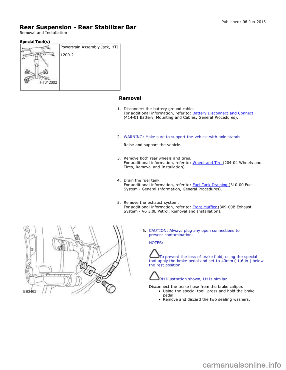
Rear Suspension - Rear Stabilizer Bar
Removal and Installation Published: 06-Jun-2013
Removal
1. Disconnect the battery ground cable.
For additional information, refer to: Battery Disconnect and Connect (414-01 Battery, Mounting and Cables, General Procedures).
2. WARNING: Make sure to support the vehicle with axle stands.
Raise and support the vehicle.
3. Remove both rear wheels and tires.
For additional information, refer to: Wheel and Tire (204-04 Wheels and Tires, Removal and Installation).
4. Drain the fuel tank.
For additional information, refer to: Fuel Tank Draining (310-00 Fuel System - General Information, General Procedures).
5. Remove the exhaust system.
For additional information, refer to: Front Muffler (309-00B Exhaust System - V6 3.0L Petrol, Removal and Installation).
6. CAUTION: Always plug any open connections to
prevent contamination.
NOTES:
To prevent the loss of brake fluid, using the special
tool apply the brake pedal and set to 40mm ( 1.6 in ) below
the rest position.
RH illustration shown, LH is similar.
Disconnect the brake hose from the brake caliper.
Using the special tool, press and hold the brake
pedal.
Remove and discard the two sealing washers. Powertrain Assembly Jack, HTJ
1200-2 Special Tool(s)
Page 423 of 3039
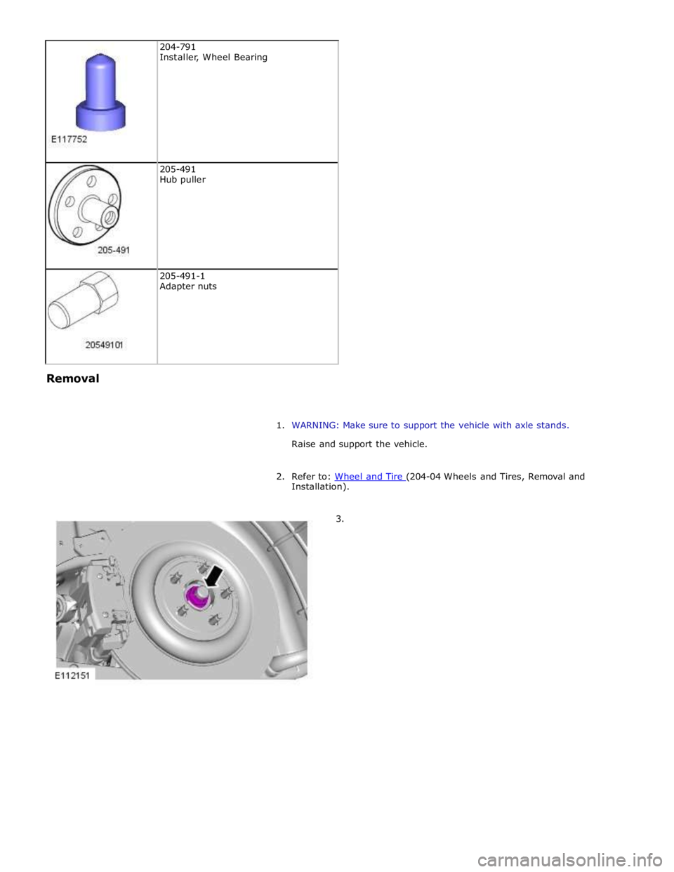
205-491
Hub puller
205-491-1
Adapter nuts Removal
1. WARNING: Make sure to support the vehicle with axle stands.
Raise and support the vehicle.
2. Refer to: Wheel and Tire (204-04 Wheels and Tires, Removal and Installation).
3.