Intake JAGUAR XFR 2010 1.G Workshop Manual
[x] Cancel search | Manufacturer: JAGUAR, Model Year: 2010, Model line: XFR, Model: JAGUAR XFR 2010 1.GPages: 3039, PDF Size: 58.49 MB
Page 13 of 3039

Throttle Body303-05D: Accessory Drive - V8 S/C 5.0L PetrolSpecificationDescription and OperationComponent Location
OverviewRemoval and InstallationAccessory Drive Belt
Accessory Drive Belt Idler Pulley
Accessory Drive Belt Tensioner
Supercharger Belt Idler Pulley
Supercharger Belt Tensioner303-06C: Starting System - V8 5.0L Petrol/V8 S/C 5.0L PetrolSpecificationDescription and OperationComponent Location
Overview
System Operation and Component DescriptionDiagnosis and TestingStarting System
Starting System - Vehicles With: Smart KeyRemoval and InstallationStarter Motor303-07B: Engine Ignition - V8 5.0L Petrol/V8 S/C 5.0L PetrolSpecificationDescription and OperationComponent Location
Overview
System Operation and Component DescriptionDiagnosis and TestingEngine IgnitionRemoval and InstallationIgnition Coil-On-Plug - V8 S/C 5.0L Petrol303-08C: Engine Emission Control - V8 5.0L Petrol/V8 S/C 5.0L Petrol
Description and OperationComponent Location
Overview
System Operation and Component DescriptionDiagnosis and TestingEngine Emission Control303-12D: Intake Air Distribution and Filtering - V8 S/C 5.0L PetrolSpecification
Page 14 of 3039

Description and OperationComponent Location
Overview
System Operation and Component DescriptionDiagnosis and TestingIntake Air Distribution and FilteringRemoval and InstallationAir Cleaner Element
Air Cleaner LH
Air Cleaner RH
Air Cleaner Outlet Pipe LH
Air Cleaner Outlet Pipe RH
Air Cleaner Outlet Pipe T-Connector
Charge Air Cooler
Supercharger
Supercharger Spring Isolator303-13B: Evaporative Emissions - V8 5.0L Petrol/V8 S/C 5.0L PetrolSpecificationDescription and OperationComponent Location
Overview
System Operation and Component DescriptionDiagnosis and TestingEvaporative EmissionsRemoval and InstallationEvaporative Emission Canister
Evaporative Emission Canister Purge Valve - V8 S/C 5.0L Petrol303-14D: Electronic Engine Controls - V8 S/C 5.0L PetrolSpecificationDescription and OperationComponent Location
Overview
System Operation and Component DescriptionDiagnosis and TestingElectronic Engine ControlsGeneral ProceduresPowertrain Control Module (PCM) Long Drive Cycle Self-Test
Powertrain Control Module (PCM) Short Drive Cycle Self-TestRemoval and InstallationCamshaft Position (CMP) Sensor LH
Camshaft Position (CMP) Sensor RH
Catalyst Monitor Sensor LH
Page 54 of 3039

Hydrofluorocarbon HFC High tension HT Hydrocarbon HC Idle Air Control IAC
Stepper motor driven device which varies the volume of air by-passing the
throttle to maintain the programmed idle speed Intake Air Temperature IAT Temperature of intake air Inertia Fuel Shut-off IFS
An inertia system that shuts off the fuel supply when activated by pre-determined force limits brought about by (e.g.) collision Input Shaft Speed ISS Indicates input shaft speed Key On, Engine Off KOEO Key On, Engine Running KOER Kilogram (mass) kg Kilogram (force) kgf Kilogram force per square
centimeter kgf/cm²
Kilometer km Kilometer per hour km/h Kilopascal kPa Kilovolt kV Knock Sensor KS
Sensor which detects the onset of detonation, and signals the ECM to
retard the ignition Liquid Crystal Display LCD
Optical digital display system, to which applied voltage varies the way the crystals reflect light, thereby modifying the display Lighting Control Module LCM Light Emitting Diode LED Low Tension LT
Primary circuit of the ignition system, linking the battery to the primary winding in the ignition coil Left-Hand LH Left-Hand Drive LHD Mass Air Flow MAF
System which provides information on the mass flow rate of the intake air
to the engine Manifold Absolute Pressure MAP Absolute pressure of the intake manifold air Manifold Absolute Pressure and Temperature MAPT
Malfunction Indicator Lamp MIL
A required on-board indicator to alert the driver of an emission related
malfunction Meter (measurement) m Metric (screw thread, e.g. M8) M Farad F Unit of electrical capacitance Millimeter mm Millimeter of mercury mmHg Millisecond ms Model year MY Newton N SI unit of force. 1 N = 0.2248 pounds force Newton Meter Nm SI unit of torque. Must not be confused with nm (nanometer) Negative Temperature
Coefficient NTC
Naturally aspirated N/A
Fuelling system using intake air at atmospheric pressure; not supercharged or turbocharged Noise, Vibration and Harshness NVH North American Specification NAS Vehicles for sale in the USA and Canadian markets On-Board Diagnostic OBD
A system that monitors some or all computer input and output control
signals. Signal(s) outside the pre-determined limits imply a fault in the system or a related system Oxides of Nitrogen Nox Oxygen Sensor O2S A sensor which detects oxygen content in the exhaust gases On-board Refuelling Vapour Recovery ORVR
Output State Control OSC Output Shaft Speed OSS Passenger Air Bag Deactivation PAD Pulsed Secondary Air Injection PAIR Passive Anti-Theft System PATS Positive Crankcase Ventilation PCV Parameter Identification PID
An index number referring to a parameter within a module without knowledge of its storage location Park/Neutral Position PNP Pulse Width Modulation PWM Programmable Electronic
Control Units System PECUS
Process whereby a common ECM is programmed on the production line to
suit the market requirements of a particular vehicle
Page 55 of 3039
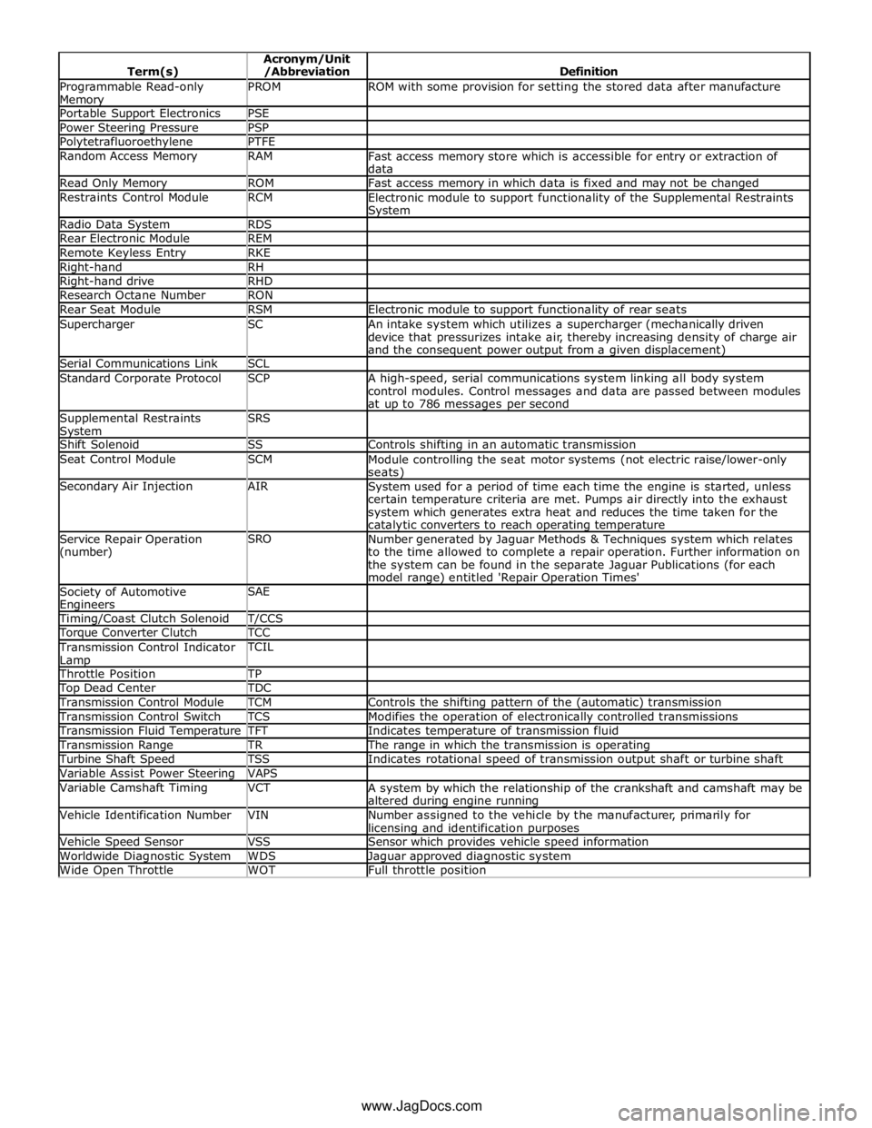
Programmable Read-only Memory PROM ROM with some provision for setting the stored data after manufacture Portable Support Electronics PSE Power Steering Pressure PSP Polytetrafluoroethylene PTFE Random Access Memory RAM
Fast access memory store which is accessible for entry or extraction of
data Read Only Memory ROM Fast access memory in which data is fixed and may not be changed Restraints Control Module RCM
Electronic module to support functionality of the Supplemental Restraints System Radio Data System RDS Rear Electronic Module REM Remote Keyless Entry RKE Right-hand RH Right-hand drive RHD Research Octane Number RON Rear Seat Module RSM Electronic module to support functionality of rear seats Supercharger SC
An intake system which utilizes a supercharger (mechanically driven
device that pressurizes intake air, thereby increasing density of charge air
and the consequent power output from a given displacement) Serial Communications Link SCL Standard Corporate Protocol SCP
A high-speed, serial communications system linking all body system
control modules. Control messages and data are passed between modules
at up to 786 messages per second Supplemental Restraints System SRS
Shift Solenoid SS Controls shifting in an automatic transmission Seat Control Module SCM
Module controlling the seat motor systems (not electric raise/lower-only seats) Secondary Air Injection AIR
System used for a period of time each time the engine is started, unless
certain temperature criteria are met. Pumps air directly into the exhaust
system which generates extra heat and reduces the time taken for the catalytic converters to reach operating temperature Service Repair Operation
(number) SRO
Number generated by Jaguar Methods & Techniques system which relates
to the time allowed to complete a repair operation. Further information on
the system can be found in the separate Jaguar Publications (for each
model range) entitled 'Repair Operation Times' Society of Automotive Engineers SAE
Timing/Coast Clutch Solenoid T/CCS Torque Converter Clutch TCC Transmission Control Indicator
Lamp TCIL
Throttle Position TP Top Dead Center TDC Transmission Control Module TCM Controls the shifting pattern of the (automatic) transmission Transmission Control Switch TCS Modifies the operation of electronically controlled transmissions Transmission Fluid Temperature TFT Indicates temperature of transmission fluid Transmission Range TR The range in which the transmission is operating Turbine Shaft Speed TSS Indicates rotational speed of transmission output shaft or turbine shaft Variable Assist Power Steering VAPS Variable Camshaft Timing VCT
A system by which the relationship of the crankshaft and camshaft may be
altered during engine running Vehicle Identification Number VIN
Number assigned to the vehicle by the manufacturer, primarily for licensing and identification purposes Vehicle Speed Sensor VSS Sensor which provides vehicle speed information Worldwide Diagnostic System WDS Jaguar approved diagnostic system Wide Open Throttle WOT Full throttle position www.JagDocs.com
Page 143 of 3039

DTC Description Possible Causes Action B11F0-11
Air Intake Damper
Position Sensor -
Circuit short to
ground
RECIRC servo motor air
intake feedback and 5
volt supply circuits -
short to ground
Refer to the electrical circuit diagrams and check RECIRC
servo motor air intake feedback and 5 volt supply circuits
for short to ground B11F0-15
Air Intake Damper
Position Sensor -
Circuit short to
battery or open
RECIRC servo motor air
intake feedback and
ground circuits - short
to power, open circuit
Carry out any pinpoint tests associated with this DTC using the manufacturer approved diagnostic system. Refer to the electrical circuit diagrams and check RECIRC servo motor air intake feedback and ground circuits for short to power, open circuit B11F8-00
Left Outer Vent -
No sub type
information
Left outer IP vent
actuator internal or
external fault
Carry out any pinpoint tests associated with this DTC using
the manufacturer approved diagnostic system B11F8-49
Left Outer Vent -
Internal electronic
failure
Left outer IP vent
actuator internal
electronic failure
Suspect the left outer IP vent actuator. Check and install a
new actuator as required, refer to the new
module/component installation note at the top of the DTC
Index B11F9-00
Left Inner Vent -
No sub type
information
Left inner IP vent
actuator internal or
external fault
Carry out any pinpoint tests associated with this DTC using
the manufacturer approved diagnostic system B11F9-49
Left Inner Vent -
Internal electronic
failure
Left inner IP vent
actuator internal
electronic failure
Suspect the left inner IP vent actuator. Check and install a
new actuator as required, refer to the new
module/component installation note at the top of the DTC
Index B11FA-00
Right Inner Vent -
No sub type
information
Right inner IP vent
actuator internal or
external fault
Carry out any pinpoint tests associated with this DTC using
the manufacturer approved diagnostic system B11FA-49
Right Inner Vent -
Internal electronic
failure
Right inner IP vent
actuator internal
electronic failure
Suspect the right inner IP vent actuator. Check and install a
new actuator as required, refer to the new
module/component installation note at the top of the DTC
Index B11FB-00
Right Outer Vent -
No sub type
information
Right outer IP vent
actuator internal or
external fault
Carry out any pinpoint tests associated with this DTC using
the manufacturer approved diagnostic system B11FB-49
Right Outer Vent -
Internal electronic
failure
Right outer IP vent
actuator internal
electronic failure
Suspect the right outer IP vent actuator. Check and install a
new actuator as required, refer to the new
module/component installation note at the top of the DTC
Index B11FF-84
A/C Refrigerant
Pressure - Signal
below allowable
range
Signal below allowable
range. A/C System
Refrigerant Pressure
too low
This DTC can be logged by the system due to low ambient
temperature soak (below 3°C) reducing the pressure in the
refrigerant gas system. If the cabin temperature logged
along with the DTC at the time is below 10°C this could
indicate low temperature. If the air conditioning
performance is satisfactory and the in-cabin temperature is
below 10°C then it is likely that the system contains a
suitable amount of gas and the DTC is being recorded as
an effect of the low ambient temperature. If this is not the
case carry out any pinpoint tests associated with this DTC
using the manufacturer approved diagnostic system. Refer
to the electrical circuit diagrams and check air conditioning
pressure sensor circuits for short, open circuit. Check for
correct charge weight B11FF-85
A/C Refrigerant
Pressure - Signal
above allowable
range
Signal above allowable
range. A/C System
Refrigerant pressure
too high
Carry out any pinpoint tests associated with this DTC using
the manufacturer approved diagnostic system. Refer to the
electrical circuit diagrams and check air conditioning
pressure sensor circuits for short, open circuit
Page 166 of 3039

DTC Description Possible Causes Action B11DB-87
Battery Monitoring Module -
Missing message
NOTE: - Circuit BATTERY -
Battery signal line circuit fault
Refer to the electrical wiring
diagrams and check the battery
monitoring system module circuit for
open circuit, short circuit to ground,
short circuit to power
Refer to the electrical circuit
diagrams and check the LIN circuit
for short circuit to ground, short
circuit to power, open circuit B1206-68
Crash Occurred - Event
information
NOTE: - Circuit SRS_SIGNAL -
Engine control module has
detected the vehicle has crashed -
event information DTC only
Refer to the electrical circuit
diagrams and check the engine
control module to restraints control
module circuit for short circuit to
ground, short circuit to power, open
circuit. Repair circuit as required,
clear the DTC and retest C0031-00
Left Front Wheel Speed
Sensor - No sub type
information
Invalid data received from anti-lock
braking system module - left front
wheel speed signal fault
Check anti-lock braking system
module for related DTCs and refer to
relevant DTC index C0034-00
Right Front Wheel Speed
Sensor - No sub type
information
Invalid data received from anti-lock
braking system module - right front
wheel speed signal fault
Check anti-lock braking system
module for related DTCs and refer to
relevant DTC index C0037-00
Left Rear Wheel Speed
Sensor - No sub type
information
Invalid data received from anti-lock
braking system module - left rear
wheel speed signal fault
Check anti-lock braking system
module for related DTCs and refer to
relevant DTC index C003A-00
Right Rear Wheel Speed
Sensor - No sub type
information
Invalid data received from anti-lock
braking system module - right rear
wheel speed signal fault
Check anti-lock braking system
module for related DTCs and refer to
relevant DTC index P0010-13
Intake (A) Camshaft Position
Actuator (Bank 1) - Circuit
open
NOTE: - Circuit VFS_IN_A -
Intake (A) camshaft position
actuator (Bank 1) open circuit
Engine control module interface
harness open circuit
Refer to the electrical circuit
diagrams and check intake (A)
camshaft position actuator (Bank 1)
circuit for open circuit
Refer to the electrical circuit
diagrams and check engine control
module interface harness for open
circuit P0011-00
Intake (A) Camshaft Position
Timing - Over-Advanced
(Bank 1) - No sub type
information
NOTE: - Circuit VFS_IN_A -
Intake (A) camshaft position
actuator (Bank 1) open circuit
Engine control module interface
harness open circuit
Refer to the electrical circuit
diagrams and check intake (A)
camshaft position actuator (Bank 1)
circuit for open circuit
Refer to the electrical circuit
diagrams and check engine control
module interface harness for open
circuit P0013-13
Exhaust (B) Camshaft
Position Actuator (Bank 1) -
Circuit open
NOTE: - Circuit VFS_EX_A -
Exhaust (B) camshaft position
actuator (Bank 1) open circuit
Engine control module interface
harness open circuit
Refer to the electrical circuit
diagrams and check exhaust (B)
camshaft position actuator (Bank 1)
circuit for open circuit
Refer to the electrical circuit
diagrams and check engine control
module interface harness for open
circuit P0015-00
Exhaust (B) Camshaft
Position Timing -
Over-Retarded (Bank 1) - No
sub type information
NOTE: - Circuit VFS_EX_A -
Exhaust (B) camshaft position
actuator (Bank 1) open circuit,
short circuit to ground, short circuit
to power
Check for related DTC P0365-00.
Refer to the electrical circuit
diagrams and check exhaust (B)
camshaft position actuator (Bank 1)
for open circuit, short circuit to
ground, short circuit to power www.JagDocs.com
Page 167 of 3039
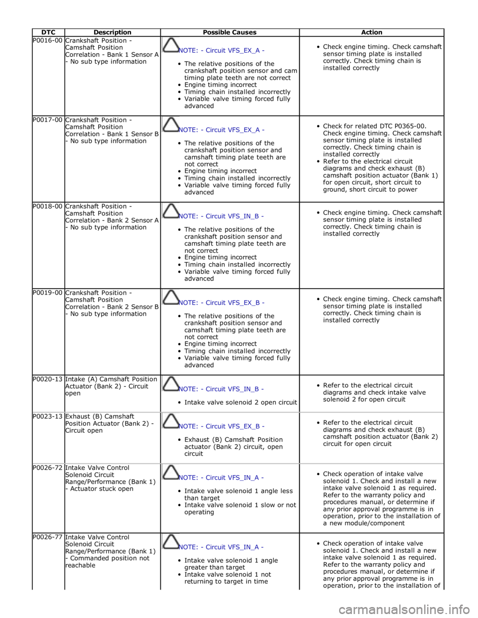
DTC Description Possible Causes Action P0016-00
Crankshaft Position -
Camshaft Position
Correlation - Bank 1 Sensor A
- No sub type information
NOTE: - Circuit VFS_EX_A -
The relative positions of the
crankshaft position sensor and cam
timing plate teeth are not correct
Engine timing incorrect
Timing chain installed incorrectly
Variable valve timing forced fully
advanced
Check engine timing. Check camshaft
sensor timing plate is installed
correctly. Check timing chain is
installed correctly P0017-00
Crankshaft Position -
Camshaft Position
Correlation - Bank 1 Sensor B
- No sub type information
NOTE: - Circuit VFS_EX_A -
The relative positions of the
crankshaft position sensor and
camshaft timing plate teeth are
not correct
Engine timing incorrect
Timing chain installed incorrectly
Variable valve timing forced fully
advanced
Check for related DTC P0365-00.
Check engine timing. Check camshaft
sensor timing plate is installed
correctly. Check timing chain is
installed correctly
Refer to the electrical circuit
diagrams and check exhaust (B)
camshaft position actuator (Bank 1)
for open circuit, short circuit to
ground, short circuit to power P0018-00
Crankshaft Position -
Camshaft Position
Correlation - Bank 2 Sensor A
- No sub type information
NOTE: - Circuit VFS_IN_B -
The relative positions of the
crankshaft position sensor and
camshaft timing plate teeth are
not correct
Engine timing incorrect
Timing chain installed incorrectly
Variable valve timing forced fully
advanced
Check engine timing. Check camshaft
sensor timing plate is installed
correctly. Check timing chain is
installed correctly P0019-00
Crankshaft Position -
Camshaft Position
Correlation - Bank 2 Sensor B
- No sub type information
NOTE: - Circuit VFS_EX_B -
The relative positions of the
crankshaft position sensor and
camshaft timing plate teeth are
not correct
Engine timing incorrect
Timing chain installed incorrectly
Variable valve timing forced fully
advanced
Check engine timing. Check camshaft
sensor timing plate is installed
correctly. Check timing chain is
installed correctly P0020-13
Intake (A) Camshaft Position
Actuator (Bank 2) - Circuit
open
NOTE: - Circuit VFS_IN_B -
Intake valve solenoid 2 open circuit
Refer to the electrical circuit
diagrams and check intake valve
solenoid 2 for open circuit P0023-13
Exhaust (B) Camshaft
Position Actuator (Bank 2) -
Circuit open
NOTE: - Circuit VFS_EX_B -
Exhaust (B) Camshaft Position
actuator (Bank 2) circuit, open
circuit
Refer to the electrical circuit
diagrams and check exhaust (B)
camshaft position actuator (Bank 2)
circuit for open circuit P0026-72
Intake Valve Control
Solenoid Circuit
Range/Performance (Bank 1)
- Actuator stuck open
NOTE: - Circuit VFS_IN_A -
Intake valve solenoid 1 angle less
than target
Intake valve solenoid 1 slow or not
operating
Check operation of intake valve
solenoid 1. Check and install a new
intake valve solenoid 1 as required.
Refer to the warranty policy and
procedures manual, or determine if
any prior approval programme is in
operation, prior to the installation of
a new module/component P0026-77
Intake Valve Control
Solenoid Circuit
Range/Performance (Bank 1)
- Commanded position not
reachable
NOTE: - Circuit VFS_IN_A -
Intake valve solenoid 1 angle
greater than target
Intake valve solenoid 1 not
returning to target in time
Check operation of intake valve
solenoid 1. Check and install a new
intake valve solenoid 1 as required.
Refer to the warranty policy and
procedures manual, or determine if
any prior approval programme is in
operation, prior to the installation of
Page 168 of 3039
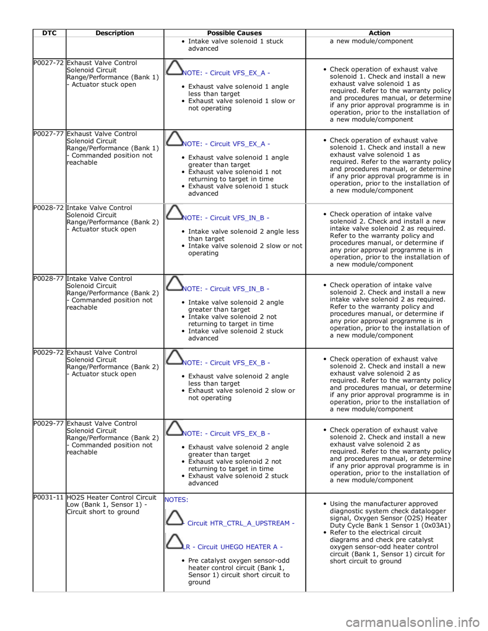
DTC Description Possible Causes Action Intake valve solenoid 1 stuck
advanced a new module/component P0027-72
Exhaust Valve Control
Solenoid Circuit
Range/Performance (Bank 1)
- Actuator stuck open
NOTE: - Circuit VFS_EX_A -
Exhaust valve solenoid 1 angle
less than target
Exhaust valve solenoid 1 slow or
not operating
Check operation of exhaust valve
solenoid 1. Check and install a new
exhaust valve solenoid 1 as
required. Refer to the warranty policy
and procedures manual, or determine
if any prior approval programme is in
operation, prior to the installation of
a new module/component P0027-77
Exhaust Valve Control
Solenoid Circuit
Range/Performance (Bank 1)
- Commanded position not
reachable
NOTE: - Circuit VFS_EX_A -
Exhaust valve solenoid 1 angle
greater than target
Exhaust valve solenoid 1 not
returning to target in time
Exhaust valve solenoid 1 stuck
advanced
Check operation of exhaust valve
solenoid 1. Check and install a new
exhaust valve solenoid 1 as
required. Refer to the warranty policy
and procedures manual, or determine
if any prior approval programme is in
operation, prior to the installation of
a new module/component P0028-72
Intake Valve Control
Solenoid Circuit
Range/Performance (Bank 2)
- Actuator stuck open
NOTE: - Circuit VFS_IN_B -
Intake valve solenoid 2 angle less
than target
Intake valve solenoid 2 slow or not
operating
Check operation of intake valve
solenoid 2. Check and install a new
intake valve solenoid 2 as required.
Refer to the warranty policy and
procedures manual, or determine if
any prior approval programme is in
operation, prior to the installation of
a new module/component P0028-77
Intake Valve Control
Solenoid Circuit
Range/Performance (Bank 2)
- Commanded position not
reachable
NOTE: - Circuit VFS_IN_B -
Intake valve solenoid 2 angle
greater than target
Intake valve solenoid 2 not
returning to target in time
Intake valve solenoid 2 stuck
advanced
Check operation of intake valve
solenoid 2. Check and install a new
intake valve solenoid 2 as required.
Refer to the warranty policy and
procedures manual, or determine if
any prior approval programme is in
operation, prior to the installation of
a new module/component P0029-72
Exhaust Valve Control
Solenoid Circuit
Range/Performance (Bank 2)
- Actuator stuck open
NOTE: - Circuit VFS_EX_B -
Exhaust valve solenoid 2 angle
less than target
Exhaust valve solenoid 2 slow or
not operating
Check operation of exhaust valve
solenoid 2. Check and install a new
exhaust valve solenoid 2 as
required. Refer to the warranty policy
and procedures manual, or determine
if any prior approval programme is in
operation, prior to the installation of
a new module/component P0029-77
Exhaust Valve Control
Solenoid Circuit
Range/Performance (Bank 2)
- Commanded position not
reachable
NOTE: - Circuit VFS_EX_B -
Exhaust valve solenoid 2 angle
greater than target
Exhaust valve solenoid 2 not
returning to target in time
Exhaust valve solenoid 2 stuck
advanced
Check operation of exhaust valve
solenoid 2. Check and install a new
exhaust valve solenoid 2 as
required. Refer to the warranty policy
and procedures manual, or determine
if any prior approval programme is in
operation, prior to the installation of
a new module/component P0031-11
HO2S Heater Control Circuit
Low (Bank 1, Sensor 1) -
Circuit short to ground NOTES:
- Circuit HTR_CTRL_A_UPSTREAM -
LR - Circuit UHEGO HEATER A -
Pre catalyst oxygen sensor-odd
heater control circuit (Bank 1,
Sensor 1) circuit short circuit to
ground
Using the manufacturer approved
diagnostic system check datalogger
signal, Oxygen Sensor (O2S) Heater
Duty Cycle Bank 1 Sensor 1 (0x03A1)
Refer to the electrical circuit
diagrams and check pre catalyst
oxygen sensor-odd heater control
circuit (Bank 1, Sensor 1) circuit for
short circuit to ground
Page 302 of 3039
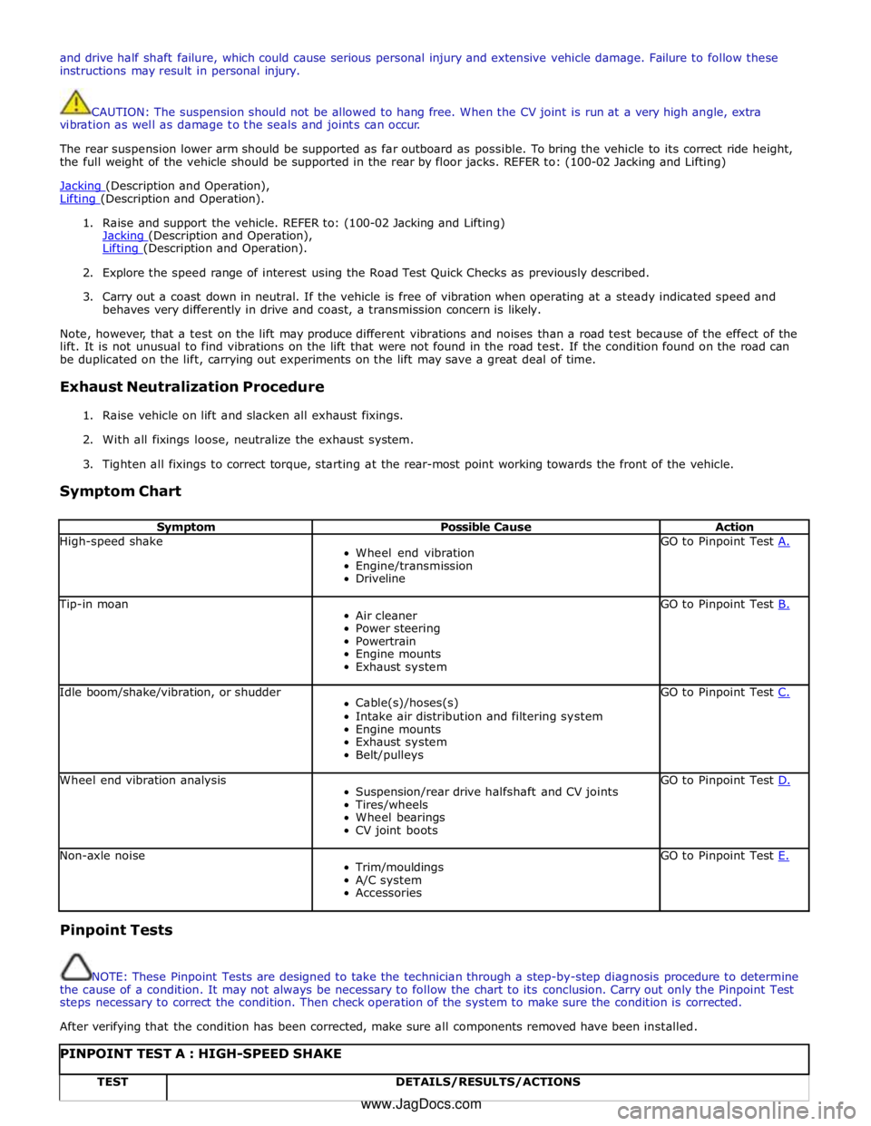
and drive half shaft failure, which could cause serious personal injury and extensive vehicle damage. Failure to follow these
instructions may result in personal injury.
CAUTION: The suspension should not be allowed to hang free. When the CV joint is run at a very high angle, extra
vibration as well as damage to the seals and joints can occur.
The rear suspension lower arm should be supported as far outboard as possible. To bring the vehicle to its correct ride height,
the full weight of the vehicle should be supported in the rear by floor jacks. REFER to: (100-02 Jacking and Lifting)
Jacking (Description and Operation), Lifting (Description and Operation).
1. Raise and support the vehicle. REFER to: (100-02 Jacking and Lifting)
Jacking (Description and Operation), Lifting (Description and Operation).
2. Explore the speed range of interest using the Road Test Quick Checks as previously described.
3. Carry out a coast down in neutral. If the vehicle is free of vibration when operating at a steady indicated speed and
behaves very differently in drive and coast, a transmission concern is likely.
Note, however, that a test on the lift may produce different vibrations and noises than a road test because of the effect of the
lift. It is not unusual to find vibrations on the lift that were not found in the road test. If the condition found on the road can
be duplicated on the lift, carrying out experiments on the lift may save a great deal of time.
Exhaust Neutralization Procedure
1. Raise vehicle on lift and slacken all exhaust fixings.
2. With all fixings loose, neutralize the exhaust system.
3. Tighten all fixings to correct torque, starting at the rear-most point working towards the front of the vehicle.
Symptom Chart
Symptom Possible Cause Action High-speed shake
Wheel end vibration
Engine/transmission
Driveline GO to Pinpoint Test A. Tip-in moan
Air cleaner
Power steering
Powertrain
Engine mounts
Exhaust system GO to Pinpoint Test B. Idle boom/shake/vibration, or shudder
Cable(s)/hoses(s)
Intake air distribution and filtering system
Engine mounts
Exhaust system
Belt/pulleys GO to Pinpoint Test C. Wheel end vibration analysis
Suspension/rear drive halfshaft and CV joints
Tires/wheels
Wheel bearings
CV joint boots GO to Pinpoint Test D. Non-axle noise
Trim/mouldings
A/C system
Accessories GO to Pinpoint Test E. Pinpoint Tests
NOTE: These Pinpoint Tests are designed to take the technician through a step-by-step diagnosis procedure to determine
the cause of a condition. It may not always be necessary to follow the chart to its conclusion. Carry out only the Pinpoint Test
steps necessary to correct the condition. Then check operation of the system to make sure the condition is corrected.
After verifying that the condition has been corrected, make sure all components removed have been installed.
PINPOINT TEST A : HIGH-SPEED SHAKE TEST DETAILS/RESULTS/ACTIONS www.JagDocs.com
Page 367 of 3039
Suspension, Removal and Installation).
3. Remove the secondary bulkhead panel LH.
For additional information, refer to: Secondary Bulkhead Panel LH - 3.0L NA V6 - AJ27 (501-02 Front End Body Panels, Removal and Installation).
4. Remove the air cleaner.
For additional information, refer to: Air Cleaner (303-12A, Removal and
Installation) /
Air Cleaner (303-12B Intake Air Distribution and Filtering - V6 3.0L Petrol, Removal and Installation) /
Air Cleaner (303-12C, Removal and Installation) /
Air Cleaner LH (303-12D, Removal and Installation).
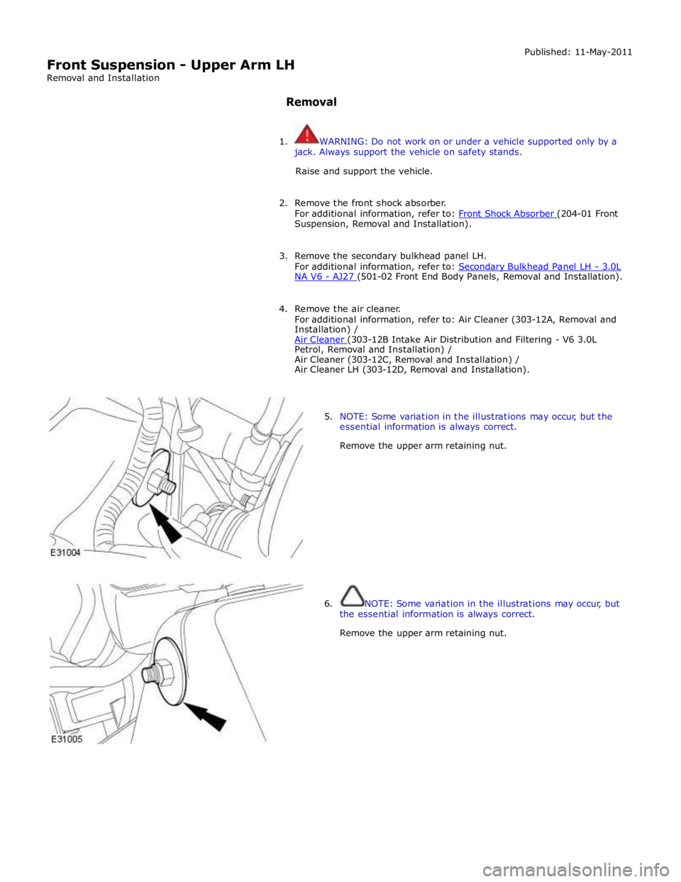
5. NOTE: Some variation in the illustrations may occur, but the
essential information is always correct.
Remove the upper arm retaining nut.
6. NOTE: Some variation in the illustrations may occur, but
the essential information is always correct.
Remove the upper arm retaining nut.