clock JAGUAR XFR 2010 1.G Owner's Manual
[x] Cancel search | Manufacturer: JAGUAR, Model Year: 2010, Model line: XFR, Model: JAGUAR XFR 2010 1.GPages: 3039, PDF Size: 58.49 MB
Page 903 of 3039
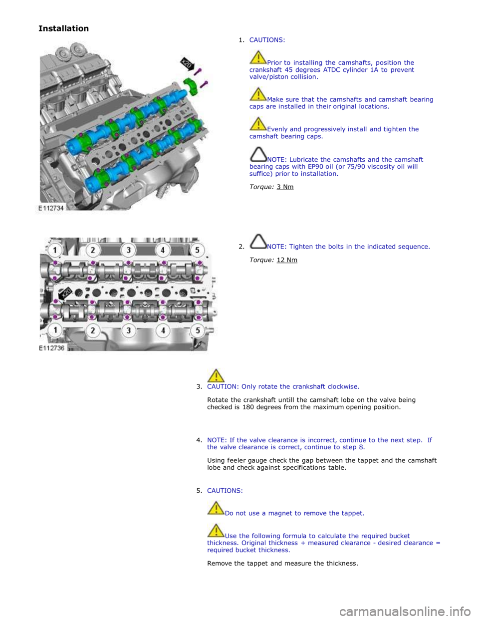
Installation
1. CAUTIONS:
Prior to installing the camshafts, position the
crankshaft 45 degrees ATDC cylinder 1A to prevent
valve/piston collision.
Make sure that the camshafts and camshaft bearing
caps are installed in their original locations.
Evenly and progressively install and tighten the
camshaft bearing caps.
NOTE: Lubricate the camshafts and the camshaft
bearing caps with EP90 oil (or 75/90 viscosity oil will
suffice) prior to installation.
Torque: 3 Nm
2. NOTE: Tighten the bolts in the indicated sequence.
Torque: 12 Nm
3. CAUTION: Only rotate the crankshaft clockwise.
Rotate the crankshaft untill the camshaft lobe on the valve being
checked is 180 degrees from the maximum opening position.
4. NOTE: If the valve clearance is incorrect, continue to the next step. If
the valve clearance is correct, continue to step 8.
Using feeler gauge check the gap between the tappet and the camshaft
lobe and check against specifications table.
5. CAUTIONS:
Do not use a magnet to remove the tappet.
Use the following formula to calculate the required bucket
thickness. Original thickness + measured clearance - desired clearance =
required bucket thickness.
Remove the tappet and measure the thickness.
Page 906 of 3039
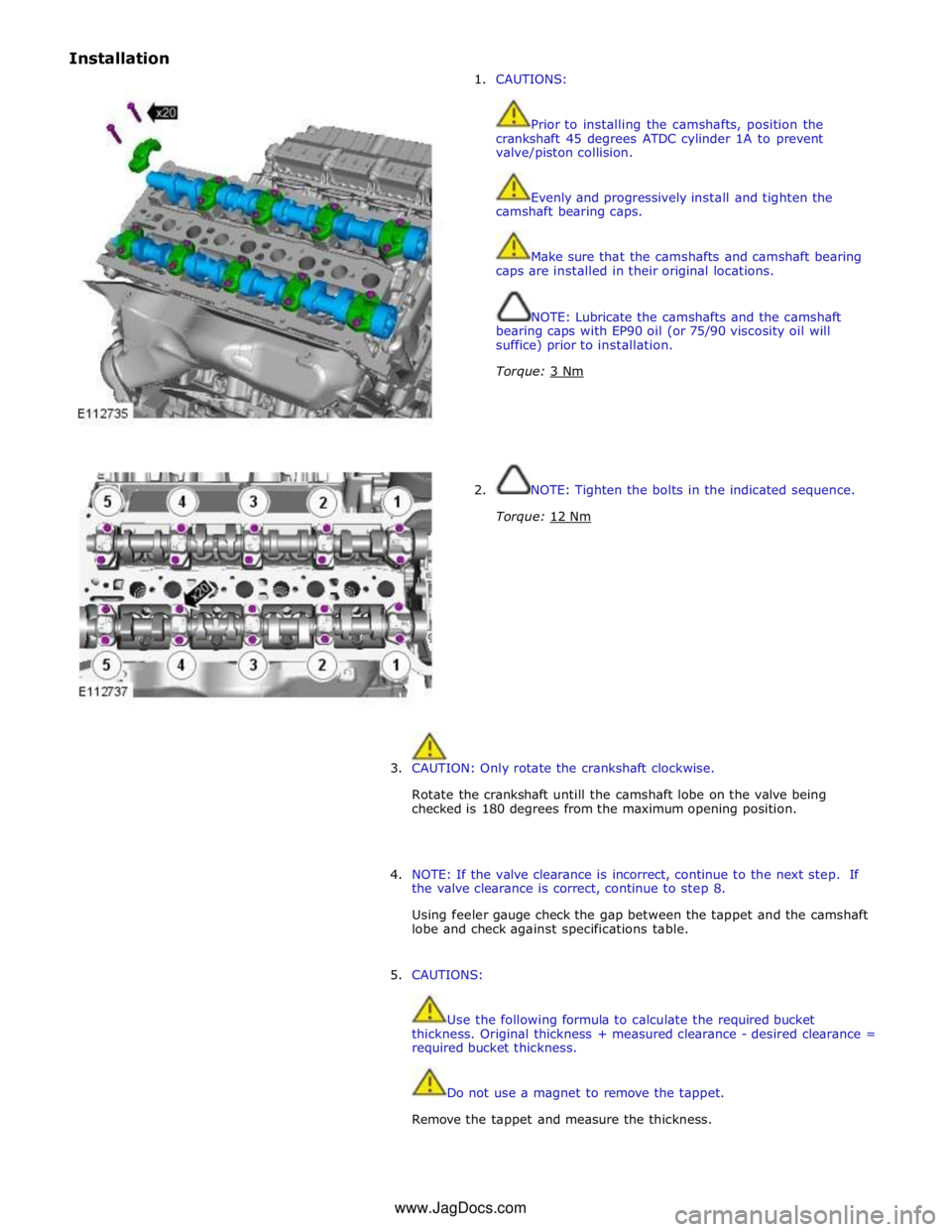
Installation
1. CAUTIONS:
Prior to installing the camshafts, position the
crankshaft 45 degrees ATDC cylinder 1A to prevent
valve/piston collision.
Evenly and progressively install and tighten the
camshaft bearing caps.
Make sure that the camshafts and camshaft bearing
caps are installed in their original locations.
NOTE: Lubricate the camshafts and the camshaft
bearing caps with EP90 oil (or 75/90 viscosity oil will
suffice) prior to installation.
Torque: 3 Nm
2. NOTE: Tighten the bolts in the indicated sequence.
Torque: 12 Nm
3. CAUTION: Only rotate the crankshaft clockwise.
Rotate the crankshaft untill the camshaft lobe on the valve being
checked is 180 degrees from the maximum opening position.
4. NOTE: If the valve clearance is incorrect, continue to the next step. If
the valve clearance is correct, continue to step 8.
Using feeler gauge check the gap between the tappet and the camshaft
lobe and check against specifications table.
5. CAUTIONS:
Use the following formula to calculate the required bucket
thickness. Original thickness + measured clearance - desired clearance =
required bucket thickness.
Do not use a magnet to remove the tappet.
Remove the tappet and measure the thickness. www.JagDocs.com
Page 923 of 3039
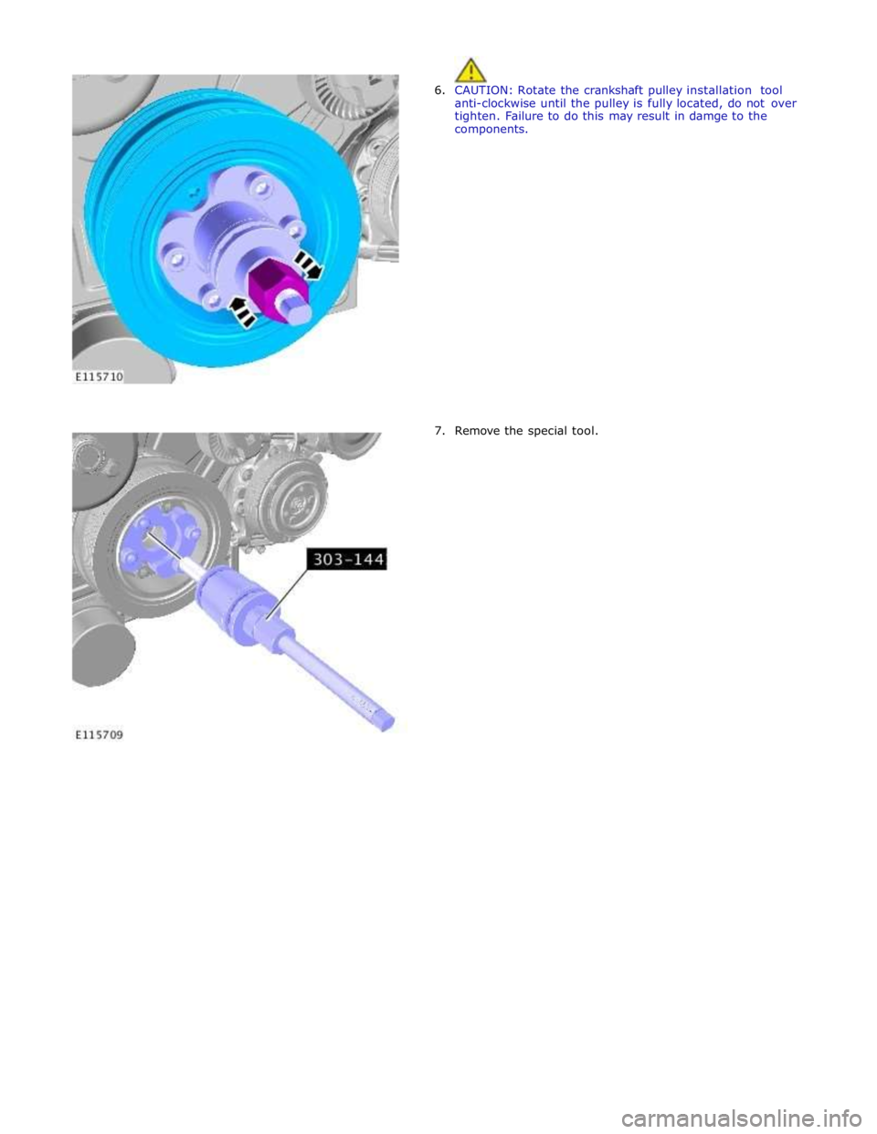
6. CAUTION: Rotate the crankshaft pulley installation tool
anti-clockwise until the pulley is fully located, do not over
tighten. Failure to do this may result in damge to the
components.
7. Remove the special tool.
Page 1033 of 3039

Some variation in the illustrations may occur, but the essential information is always correct.
1. Disconnect the battery ground cable.
Refer to: Battery Disconnect and Connect (414-01 Battery, Mounting and Cables, General Procedures).
2. WARNING: Make sure to support the vehicle with axle stands.
Raise and support the vehicle.
3. Refer to: Timing Cover (303-01C Engine - V8 5.0L Petrol, Removal and Installation).
4.
5. CAUTION: Only rotate the crankshaft clockwise.
Install the special tool.
Special Tool(s): 303-1447
Page 1034 of 3039

6. CAUTION: If the noted postion of the woodruff key is
at the 9 o'clock position, then a new flexplate must be
installed. If the woodruff key is in the 6 o'clock position
then proceed with the next step.
Note the position of the crankshaft woodruff key.
7.
Page 1041 of 3039
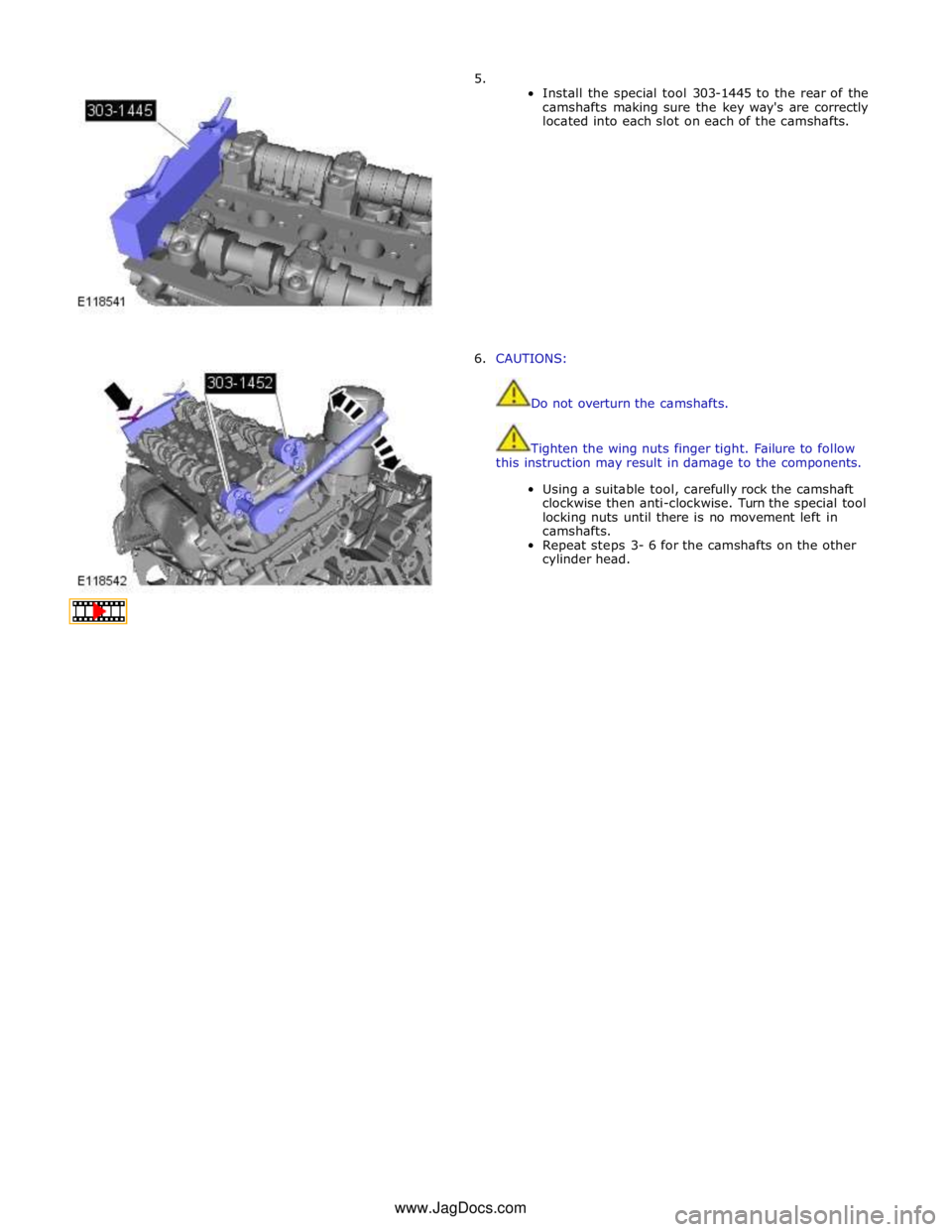
5.
Install the special tool 303-1445 to the rear of the
camshafts making sure the key way's are correctly
located into each slot on each of the camshafts.
6. CAUTIONS:
Do not overturn the camshafts.
Tighten the wing nuts finger tight. Failure to follow
this instruction may result in damage to the components.
Using a suitable tool, carefully rock the camshaft
clockwise then anti-clockwise. Turn the special tool
locking nuts until there is no movement left in
camshafts.
Repeat steps 3- 6 for the camshafts on the other
cylinder head. www.JagDocs.com
Page 1054 of 3039

32.
Remove the special tool.
Special Tool(s): 303-1448
33. Rotate the engine two complete turns clockwise.
34.
35. CAUTION: Only rotate the crankshaft clockwise.
Install the special tool.
Special Tool(s): 303-1447
Install the special tool.
Special Tool(s): 303-1448
Page 1388 of 3039

Installation 5. WARNING: Fluid loss is unavoidable, use absorbent
cloth or a container to collect the fluid.
CAUTION: Engine coolant will damage the paint
finished surfaces. If spilt, immediately remove the coolant
and clean the area with water.
Lift the tang and rotate the engine coolant temperature
(ECT) sensor counter clockwise.
1. To install, reverse the removal procedure.
Page 1412 of 3039

TCM (transmission control module) 6 Diagnostic socket 7 Instrument cluster 8 JaguarDrive selector 9 Clockspring 10 Steering wheel audio switches 11 Downshift paddle switch 12 Upshift paddle switch 13 ECM (engine control module)
POWER FLOWS System Operation
Operation of the transmission is controlled by the TCM (transmission control module), which electrically activates various
solenoids to control the transmission gear selection. The sequence of solenoid activation is based on programmed information
in the TCM memory and physical transmission operating conditions such as vehicle speed, throttle position, engine load and JaguarDrive selector position.
Item Description 1 Torque input from engine 2 Torque converter lock-up clutch 3 Single web planetary gear carrier 4 Single web planetary gears 5 Single web sunwheel 1 6 Double web sunwheel 2 7 Double web planetary gears - long 8 Double web planetary gear carrier 9 Double web planetary gears - short 10 Double web sunwheel 3 11 Torque output from transmission A Multiplate clutch B Multiplate clutch C Multiplate brake D Multiplate brake E Multiplate clutch Engine torque is transferred, via operation of single or combinations of clutches to the 2 planetary gear trains. Both gear trains
are controlled by reactionary inputs from brake clutches to produce the 6 forward gears and 1 reverse gear. The ratios are as
follows: www.JagDocs.com
Page 1426 of 3039
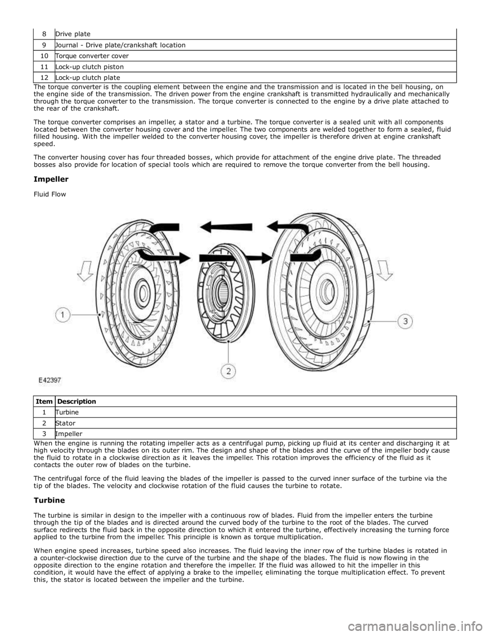
9 Journal - Drive plate/crankshaft location 10 Torque converter cover 11 Lock-up clutch piston 12 Lock-up clutch plate The torque converter is the coupling element between the engine and the transmission and is located in the bell housing, on
the engine side of the transmission. The driven power from the engine crankshaft is transmitted hydraulically and mechanically
through the torque converter to the transmission. The torque converter is connected to the engine by a drive plate attached to
the rear of the crankshaft.
The torque converter comprises an impeller, a stator and a turbine. The torque converter is a sealed unit with all components
located between the converter housing cover and the impeller. The two components are welded together to form a sealed, fluid
filled housing. With the impeller welded to the converter housing cover, the impeller is therefore driven at engine crankshaft
speed.
The converter housing cover has four threaded bosses, which provide for attachment of the engine drive plate. The threaded
bosses also provide for location of special tools which are required to remove the torque converter from the bell housing.
Impeller
Fluid Flow
Item Description 1 Turbine 2 Stator 3 Impeller When the engine is running the rotating impeller acts as a centrifugal pump, picking up fluid at its center and discharging it at
high velocity through the blades on its outer rim. The design and shape of the blades and the curve of the impeller body cause
the fluid to rotate in a clockwise direction as it leaves the impeller. This rotation improves the efficiency of the fluid as it
contacts the outer row of blades on the turbine.
The centrifugal force of the fluid leaving the blades of the impeller is passed to the curved inner surface of the turbine via the
tip of the blades. The velocity and clockwise rotation of the fluid causes the turbine to rotate.
Turbine
The turbine is similar in design to the impeller with a continuous row of blades. Fluid from the impeller enters the turbine
through the tip of the blades and is directed around the curved body of the turbine to the root of the blades. The curved
surface redirects the fluid back in the opposite direction to which it entered the turbine, effectively increasing the turning force
applied to the turbine from the impeller. This principle is known as torque multiplication.
When engine speed increases, turbine speed also increases. The fluid leaving the inner row of the turbine blades is rotated in
a counter-clockwise direction due to the curve of the turbine and the shape of the blades. The fluid is now flowing in the
opposite direction to the engine rotation and therefore the impeller. If the fluid was allowed to hit the impeller in this
condition, it would have the effect of applying a brake to the impeller, eliminating the torque multiplication effect. To prevent
this, the stator is located between the impeller and the turbine.