srs JAGUAR XFR 2010 1.G Workshop Manual
[x] Cancel search | Manufacturer: JAGUAR, Model Year: 2010, Model line: XFR, Model: JAGUAR XFR 2010 1.GPages: 3039, PDF Size: 58.49 MB
Page 2 of 3039

Table of ContentsContents1: General Information
100: Service Information
100-00: General Information
Description and OperationAbout This Manual
Application and Use of Specifications
Battery and Battery Charging Health and Safety Precautions
Brake System Health and Safety Precautions
Diesel Fuel System Health and Safety Precautions
General Service Information
Health and Safety Precautions
How To Use This Manual
Important Safety Instructions
Petrol and Petrol-Ethanol Fuel Systems Health and Safety Precautions
Solvents, Sealants and Adhesives
Standard Workshop Practices
Symbols Glossary
Supplemental Restraint System (SRS) Health and Safety Precautions
Road/Roller Testing
Window Glass Health and Safety Precautions
Diagnostic Trouble Code (DTC) IndexDTC: Adaptive Damping Module (SUMB)
Diagnostic Trouble Code (DTC) IndexDTC: Anti-Lock Braking System (ABS)
Diagnostic Trouble Code (DTC) IndexDTC: Audio Amplifier Module (AAM)
Diagnostic Trouble Code (DTC) IndexDTC: Blind Spot Monitoring System Module (SODL/SODR)
Diagnostic Trouble Code (DTC) IndexDTC: Central Junction Box (CJB)
Diagnostic Trouble Code (DTC) IndexDTC: Climate Control Module (HVAC)
Diagnostic Trouble Code (DTC) IndexDTC: Digital Audio Broadcast Module (DABM)
Diagnostic Trouble Code (DTC) IndexDTC: Driver Door Module/Passenger Door Module (DDM/PDM)
Diagnostic Trouble Code (DTC) IndexDTC: Driver/Passenger Seat Module (DSM/PSM)
Diagnostic Trouble Code (DTC) IndexDTC: Electric Parking Brake (PBM)
Diagnostic Trouble Code (DTC) Index V8 S/C 5.0L Petrol, DTC: Engine Control Module (ECM)
Diagnostic Trouble Code (DTC) IndexDTC: Front Seat Climate Control Module (DCSM)
Diagnostic Trouble Code (DTC) IndexDTC: Headlamp Control Module (HCM)
Diagnostic Trouble Code (DTC) IndexDTC: Instrument Cluster (IPC)
Diagnostic Trouble Code (DTC) IndexDTC: Integrated Audio Module (IAM)
Diagnostic Trouble Code (DTC) IndexDTC: Integrated Control Panel (FCIMB)
Page 30 of 3039

System Operation and Component DescriptionDiagnosis and TestingAir Bag and Safety Belt Pretensioner Supplemental Restraint System (SRS)General ProceduresAir Bag DisposalRemoval and InstallationB-Pillar Side Impact Sensor
Clockspring
C-Pillar Side Impact Sensor
Crash Sensor
Driver Air Bag Module
Occupant Classification Sensor
Passenger Air Bag Module
Restraints Control Module (RCM)
Side Air Bag Module (76.73.47)
Side Air Curtain Module501-20C: Pedestrian Protection System
Description and OperationComponent Location
Overview
System Operation and Component DescriptionDiagnosis and TestingPedestrian Protection SystemRemoval and InstallationPedestrian Impact Sensor
Pedestrian Protection Hood Actuator LH
Pedestrian Protection Hood Actuator RH
Pedestrian Protection Module501-25A: Body Repairs - General Information
Description and OperationBody Repairs501-25B: Body Repairs - Corrosion Protection
Description and OperationCorrosion Protection501-25C: Body Repairs - Water Leaks
Description and OperationWater Leaks501-26: Body Repairs - Vehicle Specific Information and Tolerance Checks
Description and OperationBody and Frame501-27: Front End Sheet Metal Repairs
Description and OperationFront End Sheet Metal
Page 55 of 3039

Programmable Read-only Memory PROM ROM with some provision for setting the stored data after manufacture Portable Support Electronics PSE Power Steering Pressure PSP Polytetrafluoroethylene PTFE Random Access Memory RAM
Fast access memory store which is accessible for entry or extraction of
data Read Only Memory ROM Fast access memory in which data is fixed and may not be changed Restraints Control Module RCM
Electronic module to support functionality of the Supplemental Restraints System Radio Data System RDS Rear Electronic Module REM Remote Keyless Entry RKE Right-hand RH Right-hand drive RHD Research Octane Number RON Rear Seat Module RSM Electronic module to support functionality of rear seats Supercharger SC
An intake system which utilizes a supercharger (mechanically driven
device that pressurizes intake air, thereby increasing density of charge air
and the consequent power output from a given displacement) Serial Communications Link SCL Standard Corporate Protocol SCP
A high-speed, serial communications system linking all body system
control modules. Control messages and data are passed between modules
at up to 786 messages per second Supplemental Restraints System SRS
Shift Solenoid SS Controls shifting in an automatic transmission Seat Control Module SCM
Module controlling the seat motor systems (not electric raise/lower-only seats) Secondary Air Injection AIR
System used for a period of time each time the engine is started, unless
certain temperature criteria are met. Pumps air directly into the exhaust
system which generates extra heat and reduces the time taken for the catalytic converters to reach operating temperature Service Repair Operation
(number) SRO
Number generated by Jaguar Methods & Techniques system which relates
to the time allowed to complete a repair operation. Further information on
the system can be found in the separate Jaguar Publications (for each
model range) entitled 'Repair Operation Times' Society of Automotive Engineers SAE
Timing/Coast Clutch Solenoid T/CCS Torque Converter Clutch TCC Transmission Control Indicator
Lamp TCIL
Throttle Position TP Top Dead Center TDC Transmission Control Module TCM Controls the shifting pattern of the (automatic) transmission Transmission Control Switch TCS Modifies the operation of electronically controlled transmissions Transmission Fluid Temperature TFT Indicates temperature of transmission fluid Transmission Range TR The range in which the transmission is operating Turbine Shaft Speed TSS Indicates rotational speed of transmission output shaft or turbine shaft Variable Assist Power Steering VAPS Variable Camshaft Timing VCT
A system by which the relationship of the crankshaft and camshaft may be
altered during engine running Vehicle Identification Number VIN
Number assigned to the vehicle by the manufacturer, primarily for licensing and identification purposes Vehicle Speed Sensor VSS Sensor which provides vehicle speed information Worldwide Diagnostic System WDS Jaguar approved diagnostic system Wide Open Throttle WOT Full throttle position www.JagDocs.com
Page 56 of 3039
General Information - Health and Safety Precautions
Description and Operation Published: 11-May-2011
The Health and Safety Precautions subsection refers to some commonly used chemicals and materials, hazards associated with
their use, and safety measures to be taken. Some of these chemicals may be included in the following list either in their own
right or as an ingredient in a sealer or adhesive.
Acids and Alkalis
See also Battery Acids.
e.g. caustic soda, sulphuric acid.
Used in batteries and cleaning materials.
Irritant and corrosive to the skin, eyes, nose and throat. Cause burns. Can destroy ordinary protective clothing.
Avoid splashes to the skin, eyes and clothing. Wear suitable protective impervious apron, gloves and goggles. Do not breath
mists.
Ensure access to eye wash bottles, shower and soap are readily available for splashing accidents.
Display Eye Hazard sign.
Air Bags
See also Fire, Chemical Materials - General
Highly flammable, explosive – observe No Smoking policy.
Used as a part of the Supplemental Restraint System (SRS), mounted in various positions around the vehicle.
The inflator contains a high-energetic propellant which, when ignited, produces a VERY HOT GAS (2500° C).
The gas generant used in air bags is Sodium Azide. This material is hermetically sealed in the module and is completely
consumed during deployment. No attempt should be made to open an air bag inflator as this will lead to the risk of exposure
to Sodium Azide. If a gas generator is ruptured, full protective clothing should be worn when dealing with the spillage.
After normal deployment, gloves and safety goggles should be worn during the handling process.
Deployed air bags should be disposed of in a plastic bag in accordance with local regulations at an approved chemical waste
site.
Following any direct contact with gas generant.
Wash affected areas thoroughly with water
Seek medical assistance if necessary
WARNING: To avoid accidental deployment and possible personal injury, the backup power supply must be depleted
before repairing or replacing any SRS components. To deplete the backup power supply energy, disconnect the battery negative
cable and wait for one minute. Failure to follow this instruction may result in personal injury.
NOTE: The storage, transportation, disposal and/or recycling of air bag modules must be carried out in accordance with all
applicable federal, state and local regulations including, but not limited to, those governing building and fire codes,
environmental protection, occupational health and safety and transportation.
Air Bags - Do's
Do store in an air bag safe when not installed to the vehicle.
Do store modules in an upright position
Do keep modules dry
Do carry modules with the cover side pointing away from the body
Do place modules with their cover side upwards
Do carefully inspect modules for damage
Do stand to one side when connecting modules
Do make sure all test equipment is properly calibrated and maintained
Do wash you hands after handling deployed air bags
Do wear safety glasses when carrying out repairs to the SRS or when handling an air bag module
Only carry out a system test with the air bag modules fully installed
Do inspect the condition of the impact sensor mounting bracket and sensor flylead if the vehicle has been involved in
an impact. Replace if damaged, even if there has been no deployment.
Air Bags - Do Nots
Do not store highly flammable material together with modules or gas generators
Do not store gas generators at temperatures exceeding 80° C
Page 73 of 3039
Supplementary Restraint System (SRS) Precautions
WARNING: Do not install rear facing child seats in the front passenger seat.
The SRS contains components which are potentially hazardous to service personnel if not handled correctly. The following
guidelines and precautions are intended to alert personnel to potential sources of danger and emphasise the importance of
ensuring the integrity of the SRS components installed to the vehicle.
WARNING: The following precautions MUST be adhered to when working on the SRS system:
The correct procedures must always be used when working on SRS components.
Persons working on the SRS system must be fully trained and have been issued with the safety guidelines.
The airbag modules contain extremely flammable and hazardous compounds. Contact with water, acids or heavy
metals may produce harmful or explosive results. Do not dismantle, incinerate or bring into contact with electricity
before the unit has been deployed.
Always replace a seat belt assembly that has withstood the strain of a severe vehicle impact or if the webbing
shows signs of fraying.
Always disconnect the vehicle battery before carrying out any electric welding on a vehicle installed with an SRS
system.
CAUTION: Do not expose airbag modules or seat belt pre-tensioners to temperatures exceeding 85° C (185° F).
It should be noted that these precautions are not restricted to operations performed when servicing the SRS system. The same
care should be exercised when working on ancillary systems and components located in the vicinity of SRS components; these
include but are not limited to:
Steering wheel airbag, rotary coupler.
Passenger front airbag.
Head airbag modules - front and rear.
Seat belt pre-tensioners.
SRS harnesses, link leads and connectors.
Side (thorax) air bags.
Making the system safe
Before working on or in the vicinity of SRS components, make sure the system is rendered safe by performing the following
operations:
Remove the ignition key.
Disconnect battery, earth lead first.
Wait 2 minutes for the SRS power circuit to discharge before commencing work.
NOTE: The SRS uses energy reserve capacitors to keep the system active in the event of electrical supply failure under
crash conditions. It is necessary to allow the capacitors sufficient time to discharge (2 minutes) in order to avoid the risk of
accidental deployment.
Installation
In order to make sure system integrity, it is essential that the SRS system is regularly checked and maintained so that it is
ready for effective operation in the event of a collision. Carefully inspect SRS components before installation. Do not install a
part that shows signs of being dropped or improperly handled, such as dents, cracks or deformation.
WARNING: The integrity of the SRS systems is critical for safety reasons. Make sure the following precautions are always
adhered to:
Do not install accessories or other objects to trim panels which cover ITS airbags.
Never install used SRS components from another vehicle or attempt to repair an SRS component.
When repairing an SRS system, only use genuine new parts.
Never apply electrical power to an SRS component unless instructed to do so as part of an approved test
procedure.
Special fixings are necessary for installing an airbag module – do not use other fixings and make sure that all
fixings are tightened to the correct torque.
Always use new fixings when replacing an SRS component.
CAUTIONS:
Take care not to trap airbag modules when installing interior trim components.
Make sure SRS components are not contaminated by oil or grease.
NOTES:
Following seat belt pre-tensioner deployment, the seat belts can still be used as conventional seat belts but will need to
Page 74 of 3039
be replaced as soon as possible to make sure full SRS protection.
If the SRS components are to be replaced, the part number/bar code of the new unit must be recorded.
SRS component testing precautions
The SRS components are triggered using relatively low operating currents, always adhere to the following :
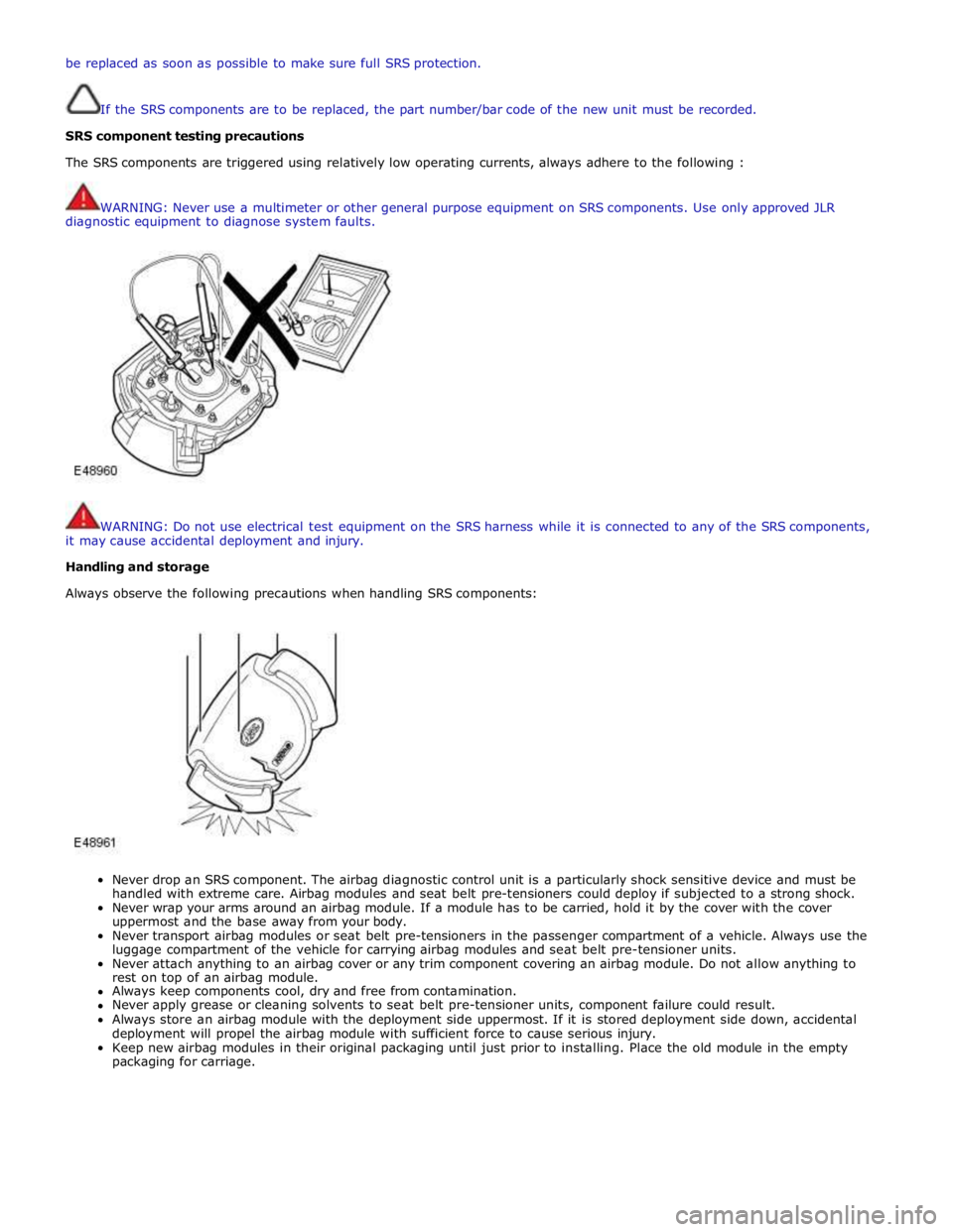
WARNING: Never use a multimeter or other general purpose equipment on SRS components. Use only approved JLR
diagnostic equipment to diagnose system faults.
WARNING: Do not use electrical test equipment on the SRS harness while it is connected to any of the SRS components,
it may cause accidental deployment and injury.
Handling and storage
Always observe the following precautions when handling SRS components:
Never drop an SRS component. The airbag diagnostic control unit is a particularly shock sensitive device and must be
handled with extreme care. Airbag modules and seat belt pre-tensioners could deploy if subjected to a strong shock.
Never wrap your arms around an airbag module. If a module has to be carried, hold it by the cover with the cover
uppermost and the base away from your body.
Never transport airbag modules or seat belt pre-tensioners in the passenger compartment of a vehicle. Always use the
luggage compartment of the vehicle for carrying airbag modules and seat belt pre-tensioner units.
Never attach anything to an airbag cover or any trim component covering an airbag module. Do not allow anything to
rest on top of an airbag module.
Always keep components cool, dry and free from contamination.
Never apply grease or cleaning solvents to seat belt pre-tensioner units, component failure could result.
Always store an airbag module with the deployment side uppermost. If it is stored deployment side down, accidental
deployment will propel the airbag module with sufficient force to cause serious injury.
Keep new airbag modules in their original packaging until just prior to installing. Place the old module in the empty
packaging for carriage.
Page 75 of 3039
WARNINGS:
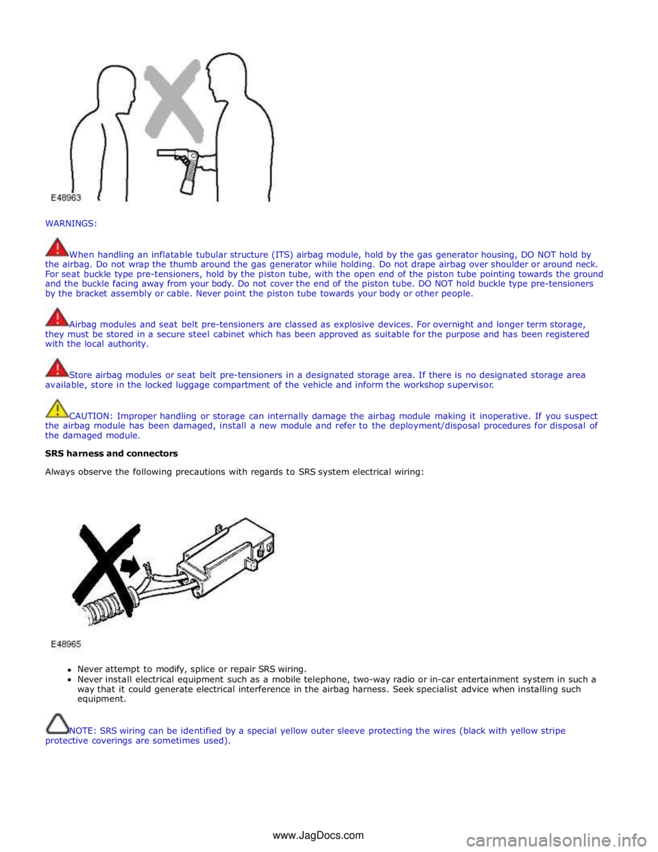
When handling an inflatable tubular structure (ITS) airbag module, hold by the gas generator housing, DO NOT hold by
the airbag. Do not wrap the thumb around the gas generator while holding. Do not drape airbag over shoulder or around neck.
For seat buckle type pre-tensioners, hold by the piston tube, with the open end of the piston tube pointing towards the ground
and the buckle facing away from your body. Do not cover the end of the piston tube. DO NOT hold buckle type pre-tensioners
by the bracket assembly or cable. Never point the piston tube towards your body or other people.
Airbag modules and seat belt pre-tensioners are classed as explosive devices. For overnight and longer term storage,
they must be stored in a secure steel cabinet which has been approved as suitable for the purpose and has been registered
with the local authority.
Store airbag modules or seat belt pre-tensioners in a designated storage area. If there is no designated storage area
available, store in the locked luggage compartment of the vehicle and inform the workshop supervisor.
CAUTION: Improper handling or storage can internally damage the airbag module making it inoperative. If you suspect
the airbag module has been damaged, install a new module and refer to the deployment/disposal procedures for disposal of
the damaged module.
SRS harness and connectors
Always observe the following precautions with regards to SRS system electrical wiring:
Never attempt to modify, splice or repair SRS wiring.
Never install electrical equipment such as a mobile telephone, two-way radio or in-car entertainment system in such a
way that it could generate electrical interference in the airbag harness. Seek specialist advice when installing such
equipment.
NOTE: SRS wiring can be identified by a special yellow outer sleeve protecting the wires (black with yellow stripe
protective coverings are sometimes used). www.JagDocs.com
Page 76 of 3039
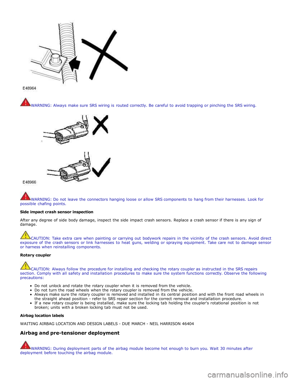
WARNING: Always make sure SRS wiring is routed correctly. Be careful to avoid trapping or pinching the SRS wiring.
WARNING: Do not leave the connectors hanging loose or allow SRS components to hang from their harnesses. Look for
possible chafing points.
Side impact crash sensor inspection
After any degree of side body damage, inspect the side impact crash sensors. Replace a crash sensor if there is any sign of
damage.
CAUTION: Take extra care when painting or carrying out bodywork repairs in the vicinity of the crash sensors. Avoid direct
exposure of the crash sensors or link harnesses to heat guns, welding or spraying equipment. Take care not to damage sensor
or harness when reinstalling components.
Rotary coupler
CAUTION: Always follow the procedure for installing and checking the rotary coupler as instructed in the SRS repairs
section. Comply with all safety and installation procedures to make sure the system functions correctly. Observe the following
precautions:
Do not unlock and rotate the rotary coupler when it is removed from the vehicle.
Do not turn the road wheels when the rotary coupler is removed from the vehicle.
Always make sure the rotary coupler is removed and installed in its central position and with the front road wheels in
the straight ahead position - refer to SRS repair section for the correct removal and installation procedure.
If a new rotary coupler is being installed, make sure the locking tab holding the coupler's rotational position is not
broken; units with a broken locking tab must not be used.
Airbag location labels
WAITING AIRBAG LOCATION AND DESIGN LABELS - DUE MARCH - NEIL HARRISON 46404
Airbag and pre-tensioner deployment
WARNING: During deployment parts of the airbag module become hot enough to burn you. Wait 30 minutes after
deployment before touching the airbag module.
Page 77 of 3039
Deployment procedures and precautions as detailed in this manual should be strictly adhered to. Only personnel who have
undergone the appropriate training should undertake deployment of airbag and pre-tensioner modules. The following
precautions must be complied with:
Only use deployment equipment approved for the intended purpose.
Deployment of airbag / pre-tensioner modules must be performed in a well ventilated area which has been designated
for the purpose.
Make sure airbag / pre-tensioner modules are not damaged or ruptured before attempting to deploy.
Where local legislation exists, notify the relevant authorities of intention to deploy airbag and pretensioner units.
When deploying airbag pre-tensioner units, make sure that all personnel are at least 15 metres (45 feet) away from the
deployment zone.
Make sure deployment tool is connected correctly, in compliance with the instructions detailed in the SRS section of this
manual. In particular, make sure deployment tool is NOT connected to battery supply before connecting to airbag
module connector.
When deploying seat belt pre-tensioners, make sure pre-tensioner unit is secured correctly to the seat.
When removing deployed airbag modules and pre-tensioner units, wear protective clothing. Use gloves and seal
deployed units in a plastic bag.
Following deployment of any component of the SRS system within the vehicle, all SRS components must be replaced.
DO NOT reuse or salvage any parts of the SRS system.
Do not lean over an airbag module when connecting deployment equipment.
If a vehicle is to be scrapped, undeployed airbag modules and pre-tensioner units must be manually deployed. In this case
airbags can be deployed in the vehicle. Before deployment, make sure the airbag module is secure within its correct mounting
position. Deployment of the driver's airbag in the vehicle may damage the steering wheel; if the vehicle is not being scrapped,
deploy the module outside of the vehicle.
SRS Component Replacement Policy
CAUTIONS:
The Restraints Control Module (RCM) will log a crash fault after every impact which is severe enough to cause airbag
deployment. It is possible to have three crashes/impacts logged after one event where, for example, a front, side and
rollover has occurred. After the third fault is logged, the SRS warning lamp will be illuminated and the RCM must be
installed. After any airbag deployment a new RCM must be installed.
The SRS side impact sensor must be replaced if there are any signs of physical damage or if the restraints control module
(RCM) is registering a fault.
The following information details the policy for replacement of SRS components as a result of a vehicle accident.
Impacts which do not deploy the airbags or pre-tensioners
Check for structural damage in the area of the impact paying particular attention to bumper armatures, longitudinals and
bracketry.
Impacts which deploy the airbags or pre-tensioners
The replacement and inspection policy is dependent on the type and severity of the crash condition. The following guidelines
are the minimum that should be exercised as a result of the deployment of specific SRS components.
Check for structural damage in the area of impact paying particular attention to bumper armatures, longitudinals and
bracketry.
Front Airbag Deployment - Driver and Passenger
CAUTION: If the front airbags are deployed, the following components must be replaced:
Driver airbag module
Passenger airbag module
Fly leads (where applicable) connecting front airbag modules to SRS harness
Front seat belt buckle pre-tensioner
Rear seat belt pre-tensioners - if installed
Driver's seat belt retractor - if installed
Rotary coupler
Any front impact sensors that have been physically damaged or if a fault is being registered
Restraints control module (RCM) if the three crashes/impacts have been stored
Additionally, the following items must be inspected for damage and replaced as necessary:
Front passenger's seat belt retractor and webbing, tongue latching function, 'D' loop and body anchorage point
Rear seat belt buckles, webbing, buckle covers, body anchorage points and tongue latching function
Fascia moulding adjacent to passenger airbag module
Steering wheel
Front seat frames and head restraints
Steering column - if adjustment is lost or if there are signs of collapse
Seat belt height adjusters
Page 101 of 3039
Published: 11-May-2011
General Information - Supplemental Restraint System (SRS) Health and
Safety Precautions
Description and Operation
WARNINGS:
Only qualified technicians are allowed to work on pyrotechnic components.
INHALED: Exposure to pyrotechnic residue may cause low blood pressure, severe headache, irritation of mucous
membranes, fainting, shortness of breath or rapid pulse. Move a victim to fresh air. Seek immediate medical attention.
EYE CONTACT: Exposure to unburned pyrotechnic residue may cause irritation, burning and etching of the eyes. Flush
immediately with plenty of cold running water for at least 15 minutes. Seek immediate medical attention.
EYE CONTACT: Exposure to burned pyrotechnic residue may cause irritation, burning and etching of the eyes. Flush
immediately with diluted boric acid solution. Seek immediate medical attention.
SKIN CONTACT: Unburned pyrotechnic residue may be rapidly absorbed through the skin in toxic quantities. Wash
immediately with plenty of soap and water. Seek medical attention.
SKIN CONTACT: Burned pyrotechnic residue may be rapidly absorbed through the skin in toxic quantities. Wash with
plenty of water. Do not use soap. Seek medical attention.
SWALLOWED: Unburned pyrotechnic residue is extremely toxic. If conscious drink plenty of water then induce vomiting.
Seek immediate medical attention. If unconscious, or in convulsions do not attempt to induce vomiting or give anything by
mouth. Seek immediate medical attention.
SWALLOWED: Burned pyrotechnic residue is extremely toxic. Drink plenty of water and seek immediate medical attention.
The deployment key must only be accessible to authorized personnel.
Make sure that the deployment key remains removed from the deployment equipment except during deployment.
If permenantly disabling or enabling the passenger air bag a new seat belt for vehicles without or with a passenger air
bag must be installed.
Undeployed pyrotechnic components must not be deployed in the vehicle.
Pyrotechnic components must be deployed following local regulations.
Check thoroughly that no loose objects can be spread during the deployment of pyrotechnic components.
Pyrotechnic components must be transported following local regulations.
Never carry out any electrical measurement on disconnected, undeployed pyrotechnic components.
Pyrotechnic components must not be disassembled.
Pyrotechnic components are not interchangeable between vehicles.
Always carry a live air bag module away from the body with the air bag or trim cover pointing upwards.