steering wheel JAGUAR XJ6 1994 2.G Owner's Manual
[x] Cancel search | Manufacturer: JAGUAR, Model Year: 1994, Model line: XJ6, Model: JAGUAR XJ6 1994 2.GPages: 521, PDF Size: 17.35 MB
Page 279 of 521
~~ Body Components & Trim
e 13.3.18 Fascia 6oard - Remove
For Access And Refit
SRO 76.46.01/90
. Remove the battery cover. Disconnect the battery.
Remove the drivers side and passenger side underscuttle
. Remove the drivers airbag module, see section 15.5.
. Remove the steering wheel, section 10.
9 Remove the drivers side fascia closing panel, see sub-sec-
. Remove the passenger side fascia closing panel, see sub-
. Remove the fascia center veneer panel, see subsection
. Undo and remove the fascia tie bar securing nuts.
. Displace the tie bars.
. Undo and remove the instrument housing /fascia switch-
. Reposition the multi-plug mounting bracket.
. Disconnect the steering column control module multi-
. Disconnect the fascia switchpack harness multi-plugs.
. Displace and reposition the instrument pack for access.
. Disconnect the instrument pack harness multi-plugs.
. Remove the instrument pack / fascia switchpack assem-
. Disconnect the right hand fascia harness to cabin harness
. Disconnect the column switchgear and column motors
Disconnect the ignition switch harness multi-plug.
. Disconnect the exciter coil harness multi-plug.
. Disconnect the speaker tweeter harness multi-plug.
. Disconnect the speed control control module harness
. Undo and remove the fascia to center console securing
. Displace and remove the passenger side outlet duct.
. Disconnect the fascia harness to console harness multi-
9 Disconnect the let3 hand fascia harness to cabin harness
. Undo and remove the fascia ground eyelets to bodysecur-
. Displace and reposition the ground eyeletsfrom the stud.
. Displace and reposition the airbag control module from
Undo and remove the fascia assembly lower securing nut.
. Undo and remove the fascia outer body bracket to fascia
Carefully displace the fascia rearwards.
pads, see
sub
-sections 13.3.19 and 13.3.20.
tion 13.3.22.
section 13.3.21.
13.2.23.
pack securing screws.
0 plugs.
bly.
multi
-plug.
harness multi
-plug.
multi
-plug.
screws.
0 plugs.
multi
-plug.
ing nut.
the mounting bracket.
securing bolts.
m
0
X300 VSM Issue 1 August 1994 24
Page 280 of 521
Body Components & Trim -
. From behind the fascia passenger side, disconnect the
passenger airbag harness multi-plug.
. With assistance, remove the fascia from the vehicle and
place on a suitably protected bench.
Place the fascia
in position in the vehicle with the center
location peg correctly engaged.
Reconnect the passenger airbag module harness multi-
Plug.
. Carefully fit and align the fascia to the mounting position.
. Fit and tighten the fascia to outer body brackets securing
bolts.
Fit and tighten the fascia assembly lower securing nut.
Reposition and
fit the airbag control module to the mount-
ing bracket.
Reposition and fit the fascia harness ground eyelets to the
ground stud.
Fit and tighten the ground eyelet securing
nut.
harness multi-plug. . Reconnect the left hand fascia harness to cabin housing
. Reconnect the fascia harness to console harness multi- plugs.
Fit and align the passenger side outlet duct.
. Fit and tighten the fascia to console securing screws.
. Reconnect the speed control harness multi-plug.
. Reconnect the speaker tweeter harness multi-plug.
. Reconnect the exciter coil harness multi-plug.
Reconnect the column switchgear and column motor har-
. Reconnect the right hand fascia harness to cabin harness
. Place the instrument pack / fascia switchpack in position.
. Reconnect the instrument pack harness multi-plugs.
. Reposition and fitthe instrument packassemblytothefas-
cia.
Reconnect the fascia switchpack harness multi-plugs.
Reconnect the steering column harness multi
-plugs.
. Reposition and fit the switchpack harness multi-plug mounting bracket.
ness
multi
-plugs.
multi-plug.
. Fit and tighten the instrument pack/ switchpack securing
bolts.
- Fit and align the fascia tie bars.
. Fit and tighten the tie bar securing nuts.
9 Refit the center veneer panel.
Refit the fascia closing panels.
. Refit the steering wheel.
. Refit the drivers airbag module.
. Refit the underscuttle pads.
. Reconnect the battery and refit the battery covers.
Issue 1 August 1994 X300 VSM 25
Page 288 of 521
Body Components & Trim -
13.3.3 1 Steering Column Switchgear Mounting Bracket,
Renew
SRO 76.46.33
J 76-1 082
Fig. 1
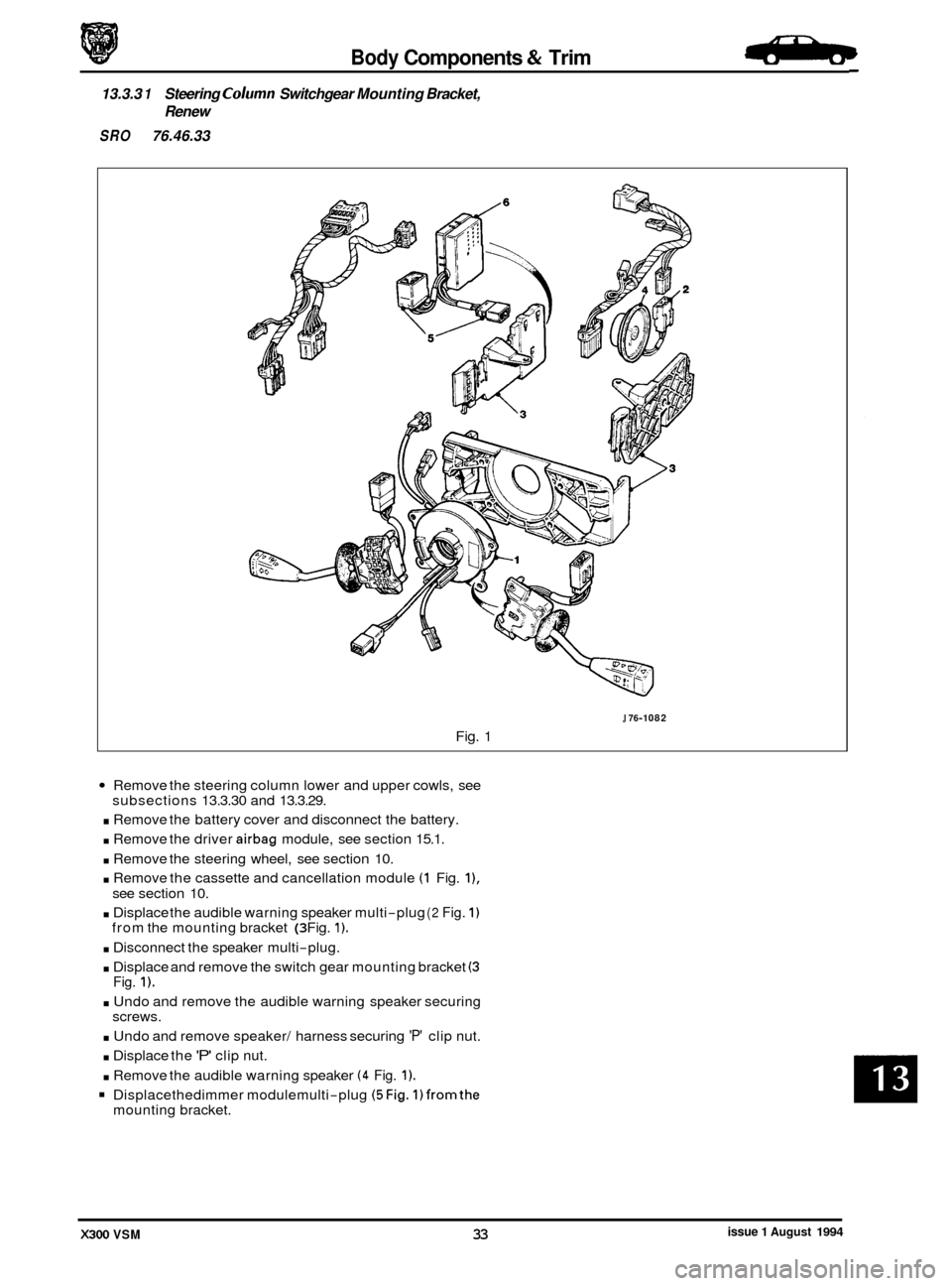
Remove the steering column lower and upper cowls, see
. Remove the battery cover and disconnect the battery.
. Remove the driver airbag module, see section 15.1.
. Remove the steering wheel, see section 10.
. Remove the cassette and cancellation module (1 Fig. I),
. Displace the audible warning speaker multi-plug (2 Fig. 1)
. Disconnect the speaker multi-plug.
. Displace and remove the switch gear mounting bracket (3
. Undo and remove the audible warning speaker securing
. Undo and remove speaker/ harness securing 'P' clip nut.
. Displace the 'P' clip nut.
. Remove the audible warning speaker (4 Fig. 1).
Displacethedimmer modulemulti-plug (5Fig. 1)fromthe
subsections 13.3.30 and 13.3.29.
see section 10.
from the mounting bracket
(3 Fig. 1).
Fig. 1).
screws.
mounting bracket.
issue 1 August 1994 X300 VSM 33
Page 289 of 521
Body Components & Trim
J76-1082
Fig. 1
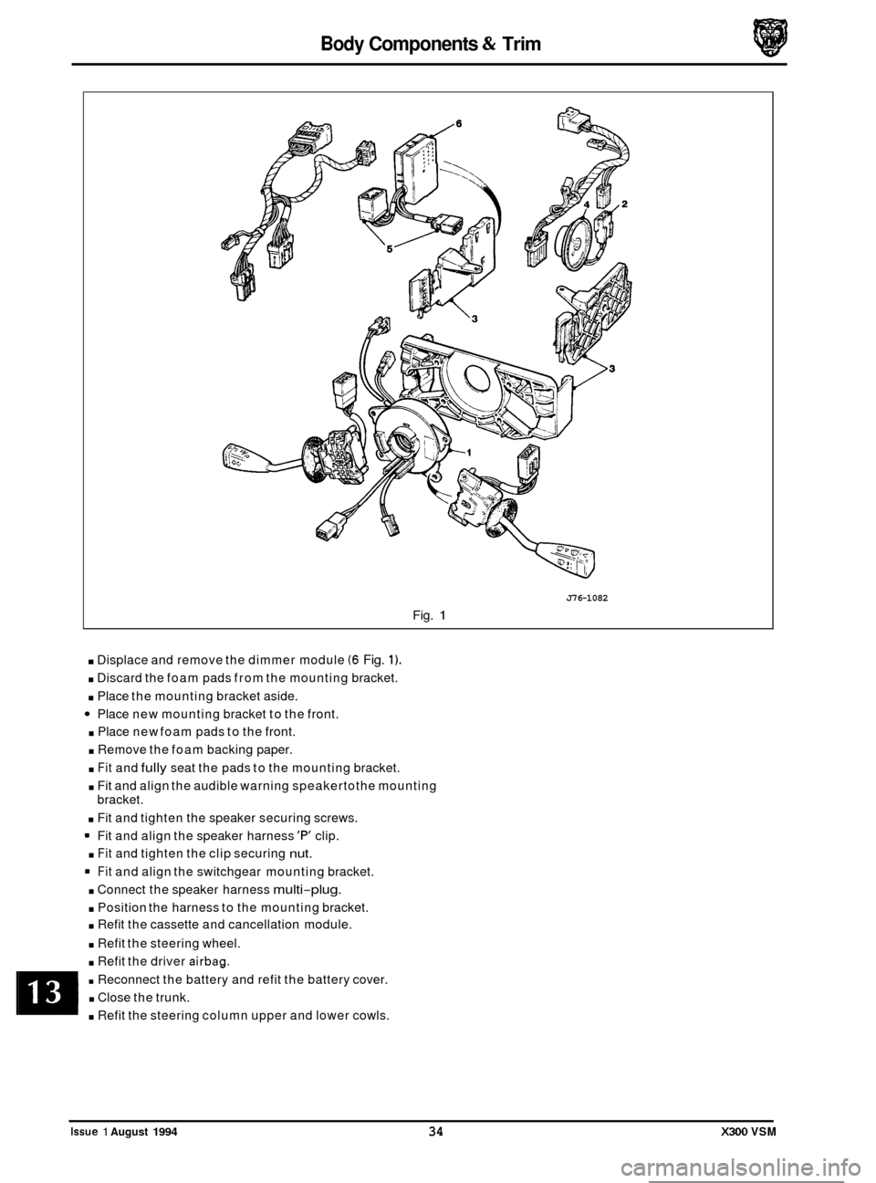
. Displace and remove the dimmer module (6 Fig. 1).
. Discard the foam pads from the mounting bracket.
. Place the mounting bracket aside.
Place new mounting bracket to the front.
. Place new foam pads to the front.
. Remove the foam backing paper.
. Fit and fully seat the pads to the mounting bracket.
. Fit and align the audible warning speakertothe mounting
bracket.
. Fit and tighten the speaker securing screws.
Fit and align the speaker harness
'F" clip.
. Fit and tighten the clip securing nut.
Fit and align the switchgear mounting bracket.
. Connect the speaker harness multi-plug.
. Position the harness to the mounting bracket.
. Refit the cassette and cancellation module.
. Refit the steering wheel.
. Refit the driver airbag.
. Reconnect the battery and refit the battery cover.
. Close the trunk.
. Refit the steering column upper and lower cowls.
0
0
0
0
Issue 1 August 1994 34 X300 VSM
Page 357 of 521
15.6
15.6.1
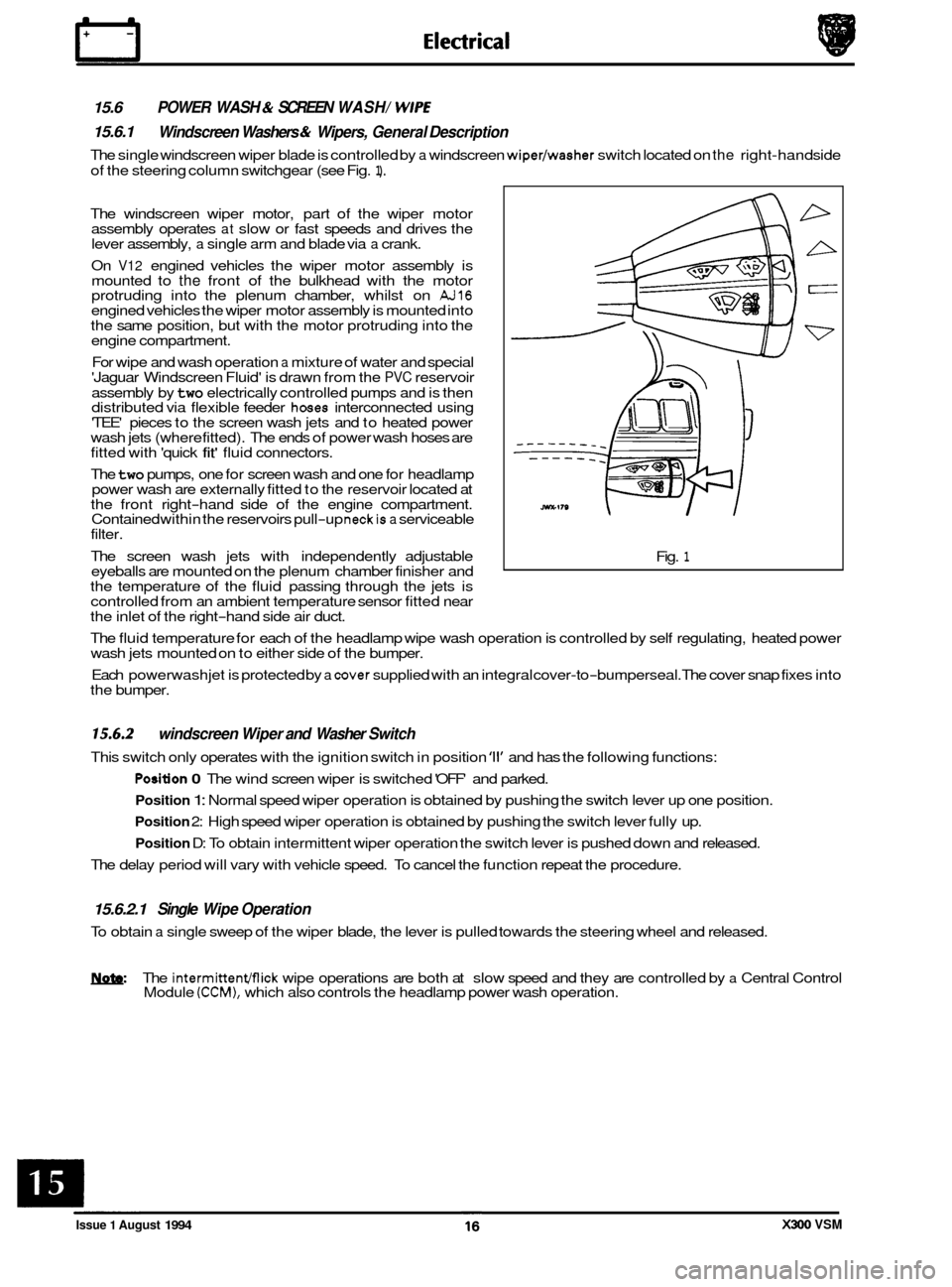
The single windscreen wiper blade is controlled by a windscreen wiper/washer switch located on the right-hand side
of the steering column switchgear (see Fig.
1).
POWER WASH & SCREEN WASH/ WlPE
Windscreen Washers & Wipers, General Description
The windscreen wiper motor, part of the wiper motor
assembly operates at slow or fast speeds and drives the
lever assembly, a single arm and blade via a crank.
On
V12 engined vehicles the wiper motor assembly is
mounted to the front of the bulkhead with the motor
protruding into the plenum chamber, whilst on AJ16 engined vehicles the wiper motor assembly is mounted into
the same position, but with the motor protruding into the
engine compartment.
For wipe and wash operation
a mixture of water and special
'Jaguar Windscreen Fluid' is drawn from the PVC reservoir
assembly by
two electrically controlled pumps and is then
distributed via flexible feeder hoses interconnected using
'TEE' pieces to the screen wash jets and to heated power
wash jets (where fitted). The ends of power wash hoses are
fitted with 'quick
fit' fluid connectors.
The
two pumps, one for screen wash and one for headlamp
power wash are externally fitted to the reservoir located at
the front right
-hand side of the engine compartment.
Contained within the reservoirs pull-up neckis a serviceable
filter.
The screen wash jets with independently adjustable
eyeballs are mounted on the plenum chamber finisher and
the temperature of the fluid passing through the jets is
controlled from an ambient temperature sensor fitted near
the inlet of the right
-hand side air duct. Fig.
1
The
fluid temperature for each of the headlamp wipe wash operation is controlled by self regulating, heated power
wash jets mounted on to either side of the bumper.
Each powerwash jet is protected by
a cover supplied with an integral cover-to-bumperseal. The cover snap fixes into
the bumper.
15.6.2
This switch only operates with the ignition switch in position '11' and has the following functions:
windscreen Wiper and Washer Switch
Position 0 The wind screen wiper is switched 'OFF' and parked.
Position 1: Normal speed wiper operation is obtained by pushing the switch lever up one position.
Position 2: High speed wiper operation is obtained by pushing the switch lever fully up.
Position D: To obtain intermittent wiper operation the switch lever is pushed down and released.
The delay period will vary with vehicle speed. To cancel the function repeat the procedure.
15.6.2.1 Single Wipe Operation
To obtain a single sweep of the wiper blade, the lever is pulled towards the steering wheel and released.
W The intermittenmick wipe operations are both at slow speed and they are controlled by a Central Control
Module (CCM), which also controls the headlamp power wash operation.
Issue 1 August 1994 X300 VSM
Page 380 of 521
86.52.01
86.91 -83
19.75.21
86.80.24
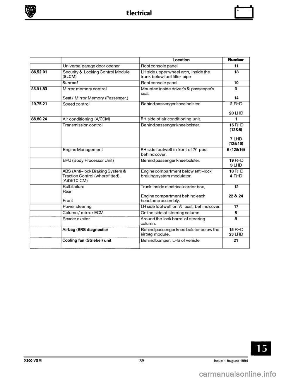
Universal garage door opener
Security
& Locking Control Module
(SLCM)
Sunroof
Mirror memory control
Seat
/ Mirror Memory (Passenger.)
Speed control
Air conditioning
(NCCM)
Transmission control
Engine Management
BPU (Body Processor Unit)
ABS (Anti
-lock Braking System &
Traction Control (where fitted).
(ABS/TC CM)
Bulb failure
Rear
Front
I Power steering
I Column / mirror ECM
Reader exciter
Location
Roof console panel
LH side upper wheel arch, inside the
trunk below fuel filler pipe
Roof console panel.
Mounted inside driver's
& passenger's
seat.
Behind passenger knee bolster.
RH side of air conditioning unit.
Behind passenger knee bolster.
RH side footwell in front of 'A' post
behind cover.
Behind passenger knee bolster.
Engine compartment below
anti-lock
braking system modulator.
Trunk inside electrical carrier box,
Engine compartment behind each
headlamp assembly.
LH side footwell on
'A' post, behind cover.
On the side of steering column.
Around the lock barrel of steering
column.
Behind passenger knee bolster below the
airbag module.
Behind bumper, LHS of vehicle
Numb
11
13
10
9
14
2
RHD
20 LHD
1
16
RHD
(1 2&6)
7 LHD
(12&16)
6 (12&16)
19 RHD
3 LHD
18 RHD
4 RHD
12
22
& 24
17 5
8
15 RHD
23 LHD
21
X300 VSM 39 issue 1 August 1994
Page 387 of 521
Steering and Suspension
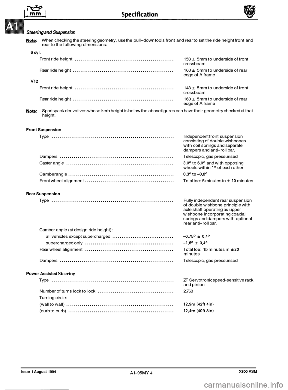
W: When checking the steering geometry, use the pull-down tools front and rear to set the ride height front and
rear to the following dimensions:
Front ride height
................................................... 153 f 5mm to underside of front
crossbeam
Rear ride height
.................................................... 160 f 5mm to underside of rear
edge of A frame
Front ride height
................................................... 143 f 5mm to underside of front
crossbeam
Rear ride height
.................................................... 160 f 5mm to underside of rear
edge of A frame
U: Sportspack derivatives whose kerb height is below the above figures can have their geometry checked at that
height.
Front Suspension
..............................................................
0
Type Independent front suspension
consisting of double wishbones
with coil springs and separate
dampers and anti
-roll bar.
Dampers
.......................................................... Telescopic, gas pressurised
Caster angle
....................................................... 3,0° to 6,0° and with opposing
wheels within Io of each other
Camberangle
...................................................... 0,3°to-0,80
Front wheel alignment .............................................. Total toe: 5 minutes in f 10 minutes
Rear Suspension
Type .............................................................. Fully independent rear suspension of double wishbone principle with
axle shaft operating as upper
wishbone incorporating coaxial
springs and dampers with optional
rear anti
-roll bar.
Camber angle
(at design ride height):
all vehicles except supercharged ................................. -0,75O f 0,4O
supercharged only -1,6O f 0,4O ..............................................
0 Rear wheel alignment .............................................. Total toe: 15 minutes in f20
Dampers .......................................................... Telescopic, gas pressurised
minutes
Power Assisted Steering
Type .............................................................. ZF
Servotronic speed-sensitive rack
and pinion
Number
of turns lock to lock ........................................ 2,768
Turning circle: (wall to wall)
....................................................... 12,9m (42ft 4in)
(curb to curb) ...................................................... 12,4m (40ft 8in)
0
X300 VSM Issue 1 August 1994 AI-95MY 4 ~~~~
Page 428 of 521
0
0
0
Body Systems Body Repair
A4.1 BODY REPAIR
Introduction
This section contains information, specifications and procedures for body repair and rectification of the Jaguar sedan
range (with standard wheelbase).
All repairs, whether structural or cosmetic, must ensure the continuance of the Paint Surface and Corrosion warranty,
where applicable.
Following repair or rectification, the vehicle must be returned to the original manufactured condition with regard to
occupant safety, dimensional accuracy, finish and corrosion protection.
Similarly, repaired vehicles must be fully checked, and where appropriate reset, with regard to steering, suspension,
restraint and
braking systems.
A4.1.1 Health and Safety
(Please Read The
Fol/owing Notes Carethlly)
Where legislation governing working conditions and practises is applicable, you should observe it. Do not forget that
you have a duty, to yourself and those around you, to act in a responsible manner in the workplace.
In the United Kingdom the Health and Safety
at Work Act (1974) places a duty on employers and employees to ensure,
whenever possible, safe working conditions and practices. Wherever a potential hazard is notified to, or identified by
the operator, he must employ the correct safety procedures and equipment.
Should
a personal injury occur as a result of any workshop activity, seek medical help as soon as possible and do not
attempt self-treatment other than by the application of first aid.
With the constant introduction of new materials in the manufacture of vehicles,
it is important that potential risks are
identified and precautions made known.
WARNING: READ AND UNDERSTAND WORKING PRACTICES CLIMATE CONTROL SYSTEMS, SECTION 14, WITH SPECIAL REFERENCE TO
ERY
/ RECYCLE / RECHARGE EQUIPMENT.
WEAR SUITABLE EYE AND SKIN PROTECTION.
OBSERVE ALL APPLICABLE SAFETY REQUIREMENTS.
DO
NOT VENT REFRIGERANT DIRECTLY TO ATMOSPHERE, ALWAYS USE JAGUAR APPROVED RECOV
-
Issue 1 August 1994 1 X300 VSM