check engine JAGUAR XJ6 1994 2.G Owner's Guide
[x] Cancel search | Manufacturer: JAGUAR, Model Year: 1994, Model line: XJ6, Model: JAGUAR XJ6 1994 2.GPages: 521, PDF Size: 17.35 MB
Page 345 of 521
rl Electrical
15.1.6 Fire Hazard Infonnath
Thermal decomposition or combustion may produce dense smoke and other dangerous fumes which in fire situations
form
a highly toxic explosive.
In the event of fire the surrounding area must be evacuated and
all personnel kept well upwind of the area.
Full fire fighting protective gear and
a self contained breathing apparatus operating in the positive pressure mode must
be worn for combating fire. Material near fires must be cooled with water spray to prevent ignition.
Fires should be allowed to burn themselves
out if not threatening to life or property. If fire is threatening to life or prop- erty use copious quantities of water to extinguish.
15.1.7 Ventilath
Local exhaust ventilation designed by a professional engineer should be provided if vapours, fumes, or dusts are gen- erated whilst working with airbag module.
The latest issue of the manual for recommended practices on 'Industrial Ventilation' is available from the
ACGIH Com- mittee on Industrial Ventilation, PO Box 16153, Lansing, MI 48910, USA.
The need for local exhaust ventilation should be evaluated by a professional industrial hygienist.
15.1.8 Respiratory Precauth
To prevent the inhalation of dangerous fumes and dusts, an approved mask should be worn.
15.1.9 Eye Protection
Chemical protective goggles are recommended where there is a possibility of eye contact with the propellant.
Safety glasses with side shields are recommended for
all other operations.
15.1. I0 Protective Clothing
Approved protective gloves, overalls and shoes / boots should be worn.
15.1.1 1 Handling and Storage Precautions
Do not store airbag module near live electrical equipment or circuitry. Store in a dry environment at ambient tempera-
tures.
Good housekeeping and engineering practices should be employed to prevent the generation and accumulation of
dusts. Store in compliance with
all local state and federal regulations.
15.1.12 Driver And Passenger Airbag Modules Assembly / Removal / Service Instructions
Before starting work, ensure ignition switch is in 'IocK position, key is removed and negative terminal cable
is disconnected from the battery.
As the airbag is equipped with a back up power source and due to the risk of airbag being inadvertently
deployed, wait one minute or longer before starting work.
0 Disconnecting the battery cancels the memory for clock, radio, seats, mirrors, steering column and any other
components using battery power. Reset memory after work is completed.
0 Never use airbags from other vehicles, always use new parts.
0 After work is completed, reconnect battery and perform warning light check see diagnostic manual.
0 Never use electrical probes to check voltage or electrical resistance.
0 Disconnect the airbag before carrying out any work on, or in the vicinity of module, or when using electric weld- ing equipment.
0 Always ensure that battery negative has been disconnected for one minute or longer before commencing any
removal procedure.
EB
Issue 1 August 1994 4 X300 VSM
Page 350 of 521
31
30
29
28 27
26
4 26 24 21 23 22 7 20 19 18 18 17 8
a
10
11
12
13
14
1s
1M-137
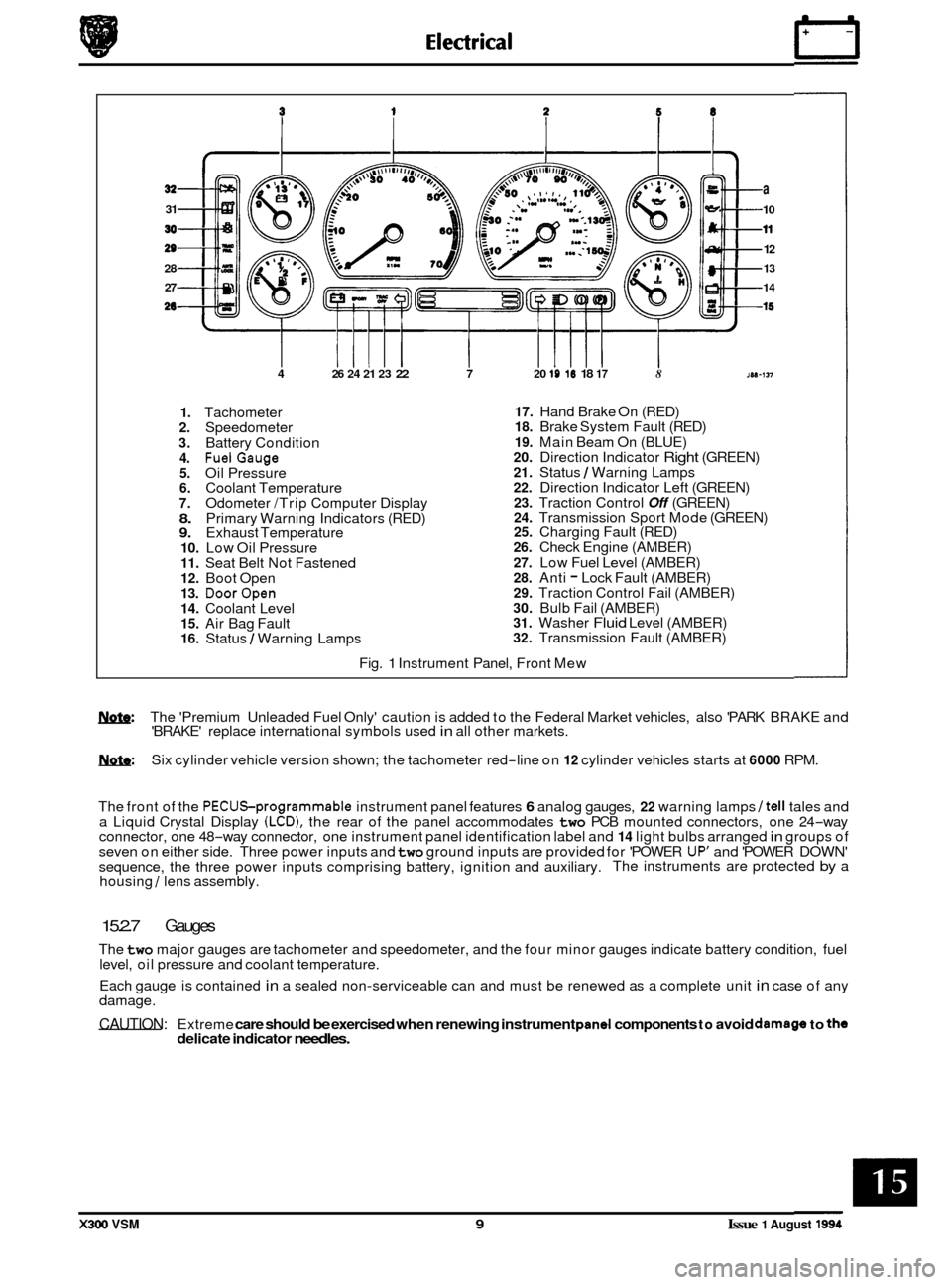
1. Tachometer 2. Speedometer
3. Battery Condition 4. FuelGauge 5. Oil Pressure 6. Coolant Temperature 7. Odometer /Trip Computer Display 8. Primary Warning Indicators (RED) 9. Exhaust Temperature 10. Low Oil Pressure 11. Seat Belt Not Fastened 12. Boot Open 13. DoorOpen 14. Coolant Level 15. Air Bag Fault 16. Status / Warning Lamps
17. Hand Brake On (RED) 18. Brake System Fault (RED)
19. Main Beam On (BLUE) 20. Direction Indicator Right (GREEN) 21. Status / Warning Lamps 22. Direction Indicator Left (GREEN) 23. Traction Control Off (GREEN) 24. Transmission Sport Mode (GREEN) 25. Charging Fault (RED) 26. Check Engine (AMBER)
27. Low Fuel Level (AMBER) 28. Anti - Lock Fault (AMBER) 29. Traction Control Fail (AMBER) 30. Bulb Fail (AMBER) 31. Washer Fluid Level (AMBER) 32. Transmission Fault (AMBER)
Fig.
1 Instrument Panel, Front Mew
w: The 'Premium Unleaded Fuel Only' caution is added to the Federal Market vehicles, also 'PARK BRAKE and
'BRAKE' replace international symbols used in all other markets.
m: Six cylinder vehicle version shown; the tachometer red-line on 12 cylinder vehicles starts at 6000 RPM.
The front of the
PECUSprogrammable instrument panel features 6 analog gauges, 22 warning lamps /tell tales and
a Liquid Crystal Display (LCD), the rear of the panel accommodates two PCB mounted connectors, one 24-way
connector, one 48-way connector, one instrument panel identification label and 14 light bulbs arranged in groups of
seven on either side. Three power inputs and two ground inputs are provided for 'POWER UP' and 'POWER DOWN'
sequence, the three power inputs comprising battery, ignition and auxiliary. The instruments are protected by a
housing
/ lens assembly.
15.2.7 Gauges
The two major gauges are tachometer and speedometer, and the four minor gauges indicate battery condition, fuel
level, oil pressure and coolant temperature.
Each gauge is contained
in a sealed non-serviceable can and must be renewed as a complete unit in case of any
damage.
CAUTION: Extreme care should be exercised when renewing instrument pand components to avoid damago to the delicate indicator needles.
X300 VSM 9 Issue 1 August 1994
Page 395 of 521
Description Capacity Type
Door guard lamp. 12V 5W Capless long life
Flasher side repeater 12V 5W Capless long life
Fog lamp - Front. 12v 55w Halogen H3
Fog lamp
- Rear guard 12v 21w Bayonet long life
Front turn indicator
I 12v21w I Bayonet long life
Pilot lamp
I 12V 5W I Capless long life
Headlamp
I 12v55w I Halogen HI
High mounted stop lamp (where fitted). 12v Capless long life
Roof console central courtesy lamp
12V 5W Capless long life.
Roof console reading lamp
12V 6W Capless
Luggage compartment lamp
12V 5W Capless long life
License plate lamp 12V 5W Festoon
Rear turn indicator
12v 21w Bayonet yellow long
Rear quarter courtesy lamp (lower section)
12V 5W Capless long life
Rear quarter reading lamp (upper section) 12V 6W Capless
Back
-up lamp 12v 21w Bayonet long life
Stop /Tail lamp
Sun visor vanity mirror lamp
12v 1,2w Capless 286
Tail lamp 12V 5W Bayonet long life
5X5W
12V 21V 5W Twin filament bayonet long life
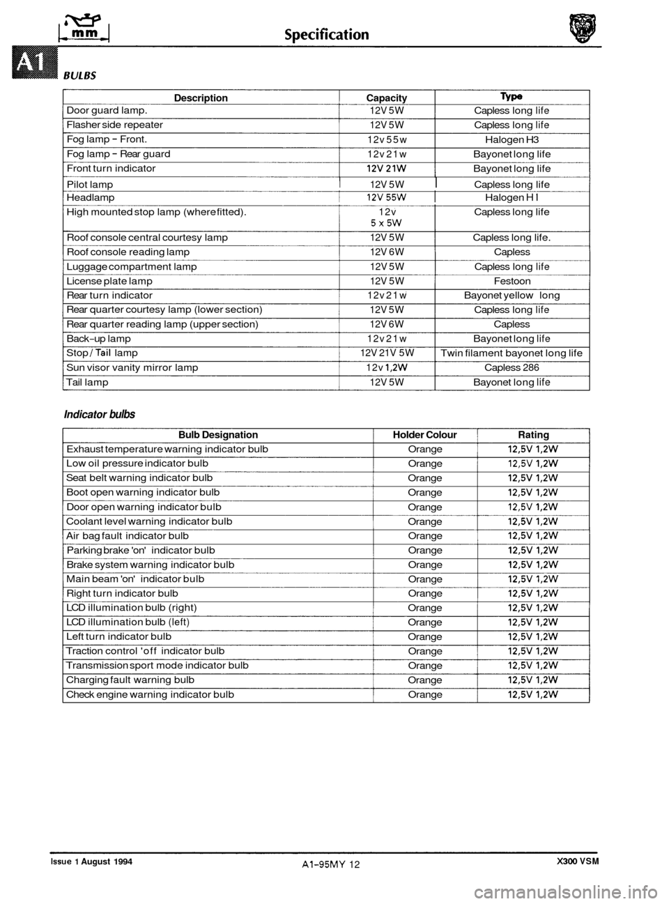
Indicator bulbs
Bulb Designation Holder Colour Rating
Exhaust temperature warning indicator bulb Orange 12,5V 1,2W
Low oil pressure indicator bulb
Orange 12,5V 1,2W
Seat belt warning indicator bulb
Orange 12,5V 1,2W
Boot open warning indicator bulb
Orange 12,5V 1,2W
Door open warning indicator bulb
Orange 12,5V 1,2W
Coolant level warning indicator bulb
Orange 12,5V 1,2W
Air bag fault indicator bulb Orange 12,5V 1,2W
Parking brake 'on' indicator bulb Orange 12,5V 1,2W
Brake system warning indicator bulb Orange 12,5V 1,2W
Main beam 'on' indicator bulb
Orange 12,5V 1,2W
Right turn indicator bulb Orange 12,5V 1,2W
LCD illumination bulb (right)
Orange 12,5V 1,2W
LCD illumination bulb (left) Orange 12,5V 1,2W
Left turn indicator bulb
Orange 12,5V 1,2W
Traction control 'off indicator bulb
Orange 12,5V 1,2W
Transmission sport mode indicator bulb
Orange 12,5V 1,2W
Charging fault warning bulb
Orange 12,5V 1,2W
Check engine warning indicator bulb Orange 12,5V 1,2W
0
0
0
X300 VSM Issue 1 August 1994 AI-95MY 12
Page 404 of 521
Routine
e
0
0
0
-
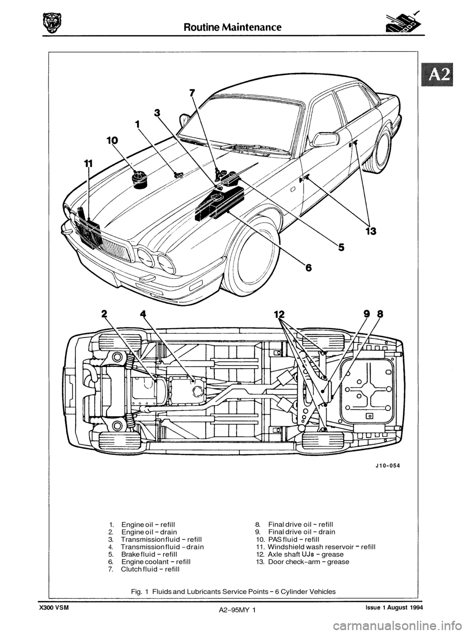
1. Engine oil - refill 2. Engine oil - drain
3. Transmission fluid - refill 4. Transmission fluid -drain 5. Brake fluid - refill 6. Engine coolant - refill 7. Clutch fluid - refill
J 10-054
8. 9.
10. PAS fluid
- refill
11. Windshield wash reservoir - refill
12. Axle shaft UJs - grease
13. Door check-arm - grease
Final
drive oil
- refill
Final drive oil - drain
Fig. 1 Fluids and Lubricants Service Points
- 6 Cylinder Vehicles
Issue 1 August 1994 A2-95MY 1 X300 VSM
Page 405 of 521
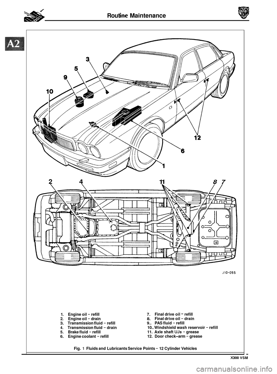
2 4 11 87
* * Rout ine Maintenance
- X300 VSM
1. Engine oil - refill
2. Engine oil - drain 3. Transmission fluid - refill
4. Transmission fluid - drain 5. Brake fluid - refill 6. Engine coolant - refill
J10-055
7. 8. 9.. PAS fluid - refill
10.. Windshield wash reservoir
- refill 11. Axle shaft UJs - grease
12. Door check-arm - grease
Final drive
oil
- refill
Final drive oil - drain
Fig.
1 Fluids and Lubricants Service Points - 12 Cylinder Vehicles
Page 408 of 521
j
8
9
10
13 I
18
19
23
24
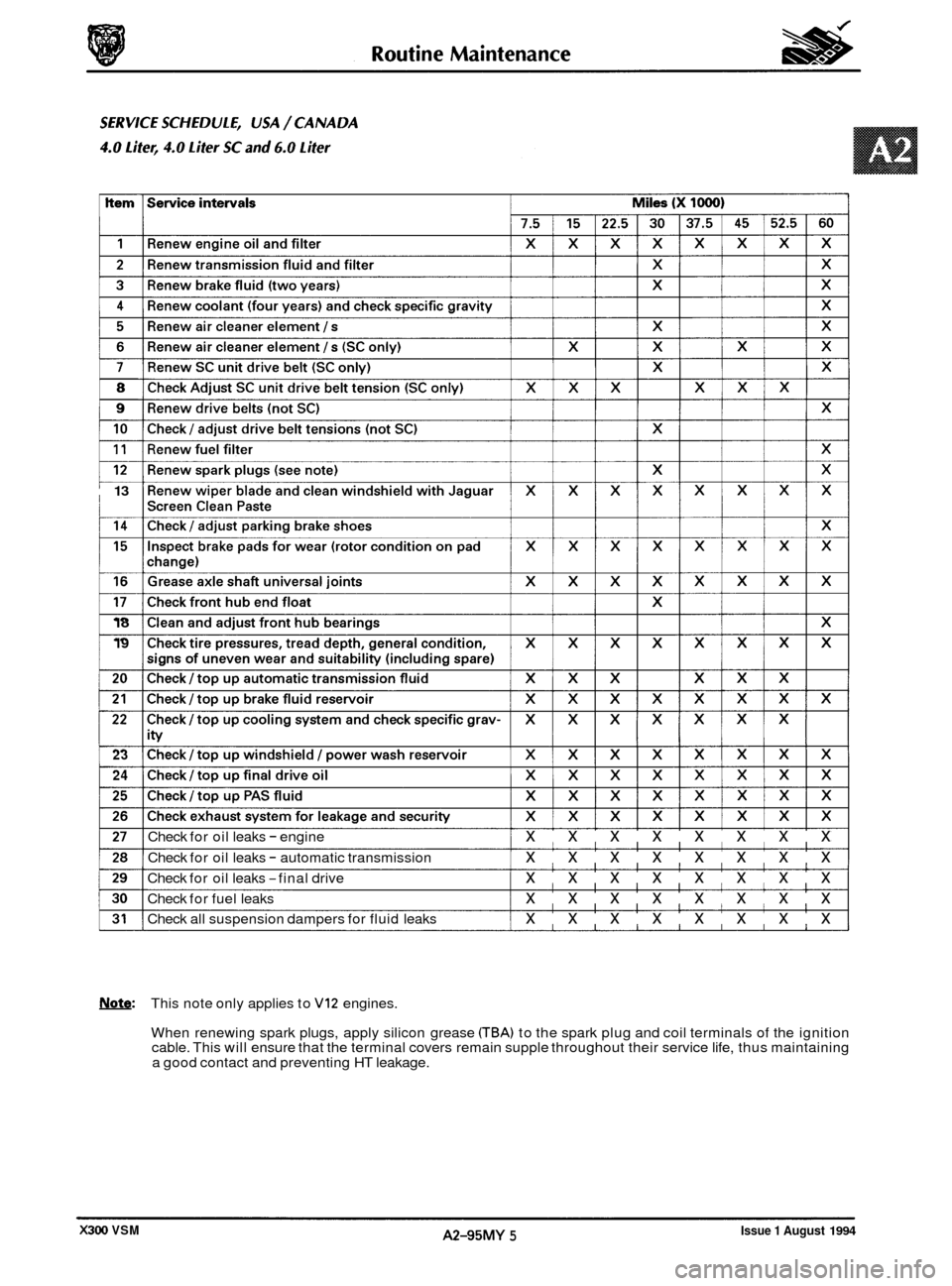
Check for oil leaks - engine xxxxxxxx
Check for oil leaks - automatic transmission xxxxxxxx
Check for oil leaks -final drive xxxxxxxx
Check for fuel leaks xxxxxxxx
Check all suspension dampers for fluid leaks xxxxxxxx
Note: This note only applies to VI2 engines.
When renewing spark plugs, apply silicon grease
CTBA) to the spark plug and coil terminals of the ignition
cable. This will ensure that the terminal covers remain supple throughout their service life, thus maintaining
a good contact and preventing HT leakage.
Issue 1 August 1994 A2-95MY 5 X300 VSM
Page 412 of 521
used.
WARNING: FUME EXTRACTION EQUIPMENT MUST BE IN OPERATION WHEN SOLVENTS ARE USED E.G.
TRICHLOROETHANE, WHITE SPIRIT, SBPB, METHYLENE CHLORIDE, PERCHLORETHYLENE.
DO NOT SMOKE IN THE VICINITY OF VOLATILE DEGREASING AGENTS.
Adhere strictly to handling and safety instructions given on containers and labels. Keep oils and solvents away from
naked flames and other sources of ignition. Do not apply heat in an attempt to free seized nuts or fittings; as well as
causing damage to protective coatings, there is
a risk of damage from stray heat to electronic equipment and brake
lines. Do not leave tools, equipment, spilt oil etc. around or on work
area. Wear protective overalls and use barrier
cream when necessary.
0 A3.1.1 Used Engine Oils
Prolonged and repeated contact with mineral oil will result in the removal of natural oils from the skin, leading to dry- ness, irritation and dermatitis. In addition, used engine oil contains potentially harmful contaminants which may cause
skin cancer. Washing facilities and adequate means of skin protection should be provided.
A3.1.2 Health Protection Precautions
0 Avoid prolonged and repeated contact with oil; particularly used engine oils.
o Wear protective clothing, including impervious gloves where practicable
0 Do not put oily rags in pockets.
0 Avoid contaminating clothes, particularly underwear, with oil.
0 Overalls must be cleaned regularly. Discard unwashable clothing and footwear which is oil impregnated.
o First Aid treatment should be obtained immediately for open cuts or wounds.
0 Use barrier creams, applying before each work period, to enable easier removal of dirty oil / grease from the
skin.
0 Wash with soap and water to ensure that all oil is removed (skin cleaner and a nail brush will help). The use of
preparations containing lanolin will help to replace the natural skin oils which have been removed.
o Do not use petrol, kerosene, gas oil, thinners or solvents for washing skin.
0 If skin disorders develop, obtain medical advice immediately.
0 Where practicable, degrease components prior to handling.
0 Where there is a risk of fluids coming into contact with the eyes, eye protection should be worn, for example,
goggles or a face shield. An eye wash facility should be provided.
A3.1.3 Environmental Protection Precautions
A3.1 SAFETY PRECAUTIONS
Whenever possible, use a ramp or pit whilst working beneath a car, in preference to jacking. Position chocks at the
wheels as well as applying the handbrake. Never rely on a jack alone to support a car. Use axle stands, or blocks care- fully placed at the jacking points, to provide a rigid location. Checkthat any lifting equipment used has adequate capac- ity and is fully serviceable. Ensure that a suitable form of fire extinguisher is conveniently located.
When using
electrical tools and equipment, inspect the power lead for damage and check that it is properly earthed. Disconnect
the earth (grounded) terminal of the car battery. Do not disconnect any pipes of the air conditioning refrigeration sys-
tem unless you are trained and instructed to do so. A refrigerant is used which can cause blindness if allowed to come
into contact with the eyes. Ensure that adequate ventilation is provided when volatile degreasing agents are being
It is illegal to pour used oil on to the ground, down sewers or drains, or into water courses. The burning of used engine
oil in small space heaters or boilers is not recommended unless emission control equipment is fitted. Dispose of used
oil through authorized waste disposal contractors, to licensed waste disposal sites or to the waste oil reclamation trade.
If in doubt, contact the Local Authority for advice on disposal facilities.
X300 VSM 1 Issue 1 August 1994
Page 413 of 521
General Fitting Instructions
A3.2 GENERAL FITTING INSTRUCTIONS
A3.2.1
Always fit covers to protect the wings before commencing work in the engine compartment. Cover the seats and
carpets, wear clean overalls and wash hands or wear gloves before working inside the car. Avoid spilling hydraulic
fluid, anti
-freeze or battery acid on the paintwork. In the event of spillage, wash off with water immediately. Use poly- thene sheets in the boot to protect carpets. Always use the recommended service tool, or a satisfactory equivalent,
where specified. Protect temporarily exposed screw threads by replacing nuts or fitting caps.
Precautions Against Damage To The Vehicle
A3.2.2 Preparation
Before disassembly, clean the surrounding area as thoroughly as possible. When components have been removed,
blank off any exposed openings using greaseproof paper and masking tape. Immediately seal fuel, oil and hydraulic
lines when separated, using plastic caps or plugs, to prevent loss of fluid and the entry of dirt. Close the open ends
of oilways, exposed by component removal, with tapered hardwood plugs or readily visible plastic plugs. Immediately
a component is removed, place
it in a suitable container; use a separate container for each component and its asso- ciated parts. Before dismantling a component, clean it thoroughly with a recommended cleaning agent: check that the
agent will not damage any of the materials within the component. Clean the bench and obtain marking materials, la-
bels, containers and locking wire before dismantling a component.
A3.2.3 Dismantling
Observe scrupulous cleanliness when dismantling components, particularly when parts of the brake, fuel or hydraulic
system are being worked on. A particle of dirt or a fragment of cloth could cause a dangerous malfunction if trapped in these systems. Clean all tapped holes, crevices, oilways and fluid passages with compressed air.
WRNIFLG: DO NOT PERMIT COMPRESSED AIR TO ENTER AN OPEN WOUND. ALWAYS USE EVE PROTECTION
WHEN USING COMPRESSED AIR.
Ensure that any 'O'-rings used for sealing are correctly refitted or renewed if disturbed. Mark mating parts to ensure
that they are replaced as dismantled. Whenever possible use marking materials which avoid the possibilities of caus- ing distortion or the initiation of cracks, which could occur if a center punch or scriber were used. Wire together mating
parts where necessary to prevent accidental interchange (e.g roller bearing components). Tie labels on to all parts to
be renewed and to parts requiring further inspection before being passed for reassembly.
Place labelled parts and other parts for rebuild
in separate containers.
Do not discard a part which is due for renewal until it has been compared with the new part, to ensure that the correct
part has been obtained.
A3.2.4 Inspection
Before inspecting a component for wear or performing a dimensional check, ensure that it is absolutely clean; a slight
smear of grease can conceal an incipient failure. When a component is to be checked dimensionally against figures
quoted for
it, use the correct equipment (surface plates, micrometers, dial gauges etc.) in serviceable condition. The
use of makeshift equipment can be dangerous. Reject a component if its dimensions are outside the limits quoted,
or if damage is apparent. A part may be refitted if its critical dimension is exactly to the limit size and it is otherwise
satisfactory. Use Plastigauge 12 Type PG-1 for checking bearing surface clearance e.g. big end bearing shell to crank
journal. Instructions for the use of Plastigauge and a scale giving bearing clearances in steps of
0,0025 mm (0.0001
in) are supplied with the package.
0
0
0
X300 VSM Issue 1 August 1994 2
Page 507 of 521
Security System - RESTRICTED ISSUE
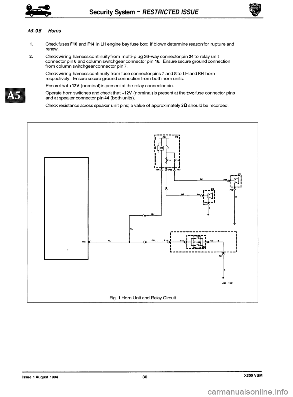
AS. 9.6 Horns
1.
2.
Check fuses FIO and F14 in LH engine bay fuse box; if blown determine reason for rupture and
renew.
Check wiring harness continuity from multi
-plug 26-way connector pin 24 to relay unit
connector pin
6 and column switchgear connector pin 16. Ensure secure ground connection
from column switchgear connector pin
7.
Check wiring harness continuity from fuse connector pins 7 and 8 to LH and RH horn
respectively. Ensure secure ground connection from both horn units.
Ensure that
+12V (nominal) is present at the relay connector pin.
Operate horn switches and check that
+12V (nominal) is present at the two fuse connector pins
and
at speaker connector pin 44 (both units).
Check resistance across speaker unit pins;
a value of approximately 2Q should be recorded.
P21.
1
r- I
$ I
I
I
I I I,, Fu
0
J86- 1911
Fig. 1 Horn Unit and Relay Circuit
X300 VSM Issue 1 August 1994 30