JAGUAR XJ6 1994 2.G Workshop Manual
Manufacturer: JAGUAR, Model Year: 1994, Model line: XJ6, Model: JAGUAR XJ6 1994 2.GPages: 521, PDF Size: 17.35 MB
Page 461 of 521

Body Systems & Body Repair
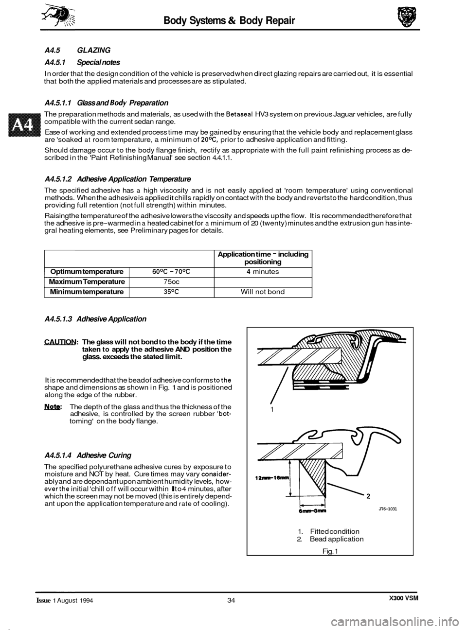
Optimum temperature 6OoC - 7OoC
Minimum temperature 35%
Maximum Temperature 7 5oc
A4.5 GLAZING
A4.5.1 Special notes
In order that the design condition of the vehicle is preserved when direct glazing repairs are carried out, it is essential
that both the applied materials and processes are as stipulated.
Application time - including
positioning
4 minutes
Will not bond
A4.5.1.1 Glass and Body Preparation
The preparation methods and materials, as used with the Betaseal HV3 system on previous Jaguar vehicles, are fully
compatible with the current sedan range.
Ease of working and extended process time may be gained by ensuring that the vehicle body and replacement glass
are 'soaked
at room temperature, a minimum of 2OoC, prior to adhesive application and fitting.
Should damage occur to the body flange finish, rectify as appropriate with the full paint refinishing process as de
- scribed in the 'Paint Refinishing Manual' see section 4.4.1.1.
A4.5.1.2 Adhesive Application Temperature
The specified adhesive has a high viscosity and is not easily applied at 'room temperature' using conventional
methods. When the adhesive is applied it chills rapidly on contact with the body and reverts to the hard condition, thus
providing full retention (not full strength) within minutes.
Raising the temperature of the adhesive lowers the viscosity and speeds up the flow.
It is recommended therefore that
the adhesive is pre-warmed in a heated cabinet for a minimum of 20 (twenty) minutes and the extrusion gun has inte- gral heating elements, see Preliminary pages for details.
A4.5.1.3 Adhesive Application
CAUTION: The glass will not bond to the body if the time
taken to apply the adhesive AND position the glass. exceeds the stated limit.
It is recommended that the bead of adhesive conforms tothe shape and dimensions as shown in Fig. 1 and is positioned
along the edge of the rubber.
m: The depth of the glass and thus the thickness of the
adhesive, is controlled by the screen rubber 'bot- toming' on the body flange.
A4.5.1.4 Adhesive Curing
The specified polyurethane adhesive cures by exposure to
moisture and NOT by heat. Cure times may vary consider- ablyand are dependant upon ambient humidity levels, how- everthe initial 'chill off will occur within l to4 minutes, after
which the screen may not be moved (this is entirely depend- ant upon the application temperature and rate of cooling). 1
12nnrl6mnr
J76-1031
1.
Fitted condition
2. Bead application
Fig. 1
X300 VSM Issue 1 August 1994 34
Page 462 of 521

Page 463 of 521

J76 -1 01 7
Fig. 1 Front bumper - Typical components
Page 464 of 521

conditions.
. Tighten all fixings to specification.
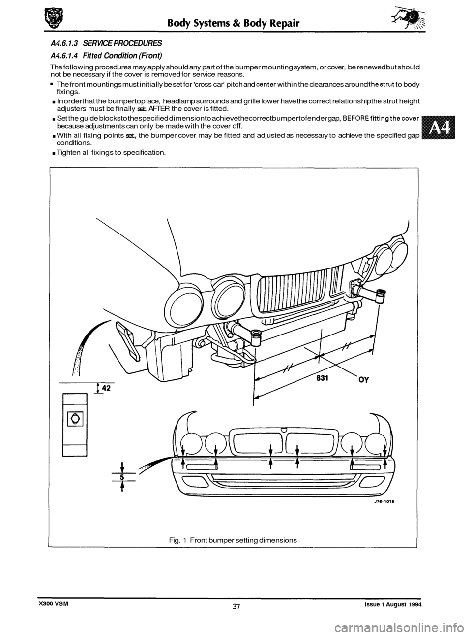
A4.6.1.3 SERVICE PROCEDURES
A4.6.1.4
Fitted Condition (Front)
The following procedures may apply should any part of the bumper mounting system, or cover, be renewed but should
not be necessary if the cover is removed for service reasons.
The front mountings must initially be set for 'cross car' pitch and center within the clearances around thestrut to body
. In orderthat the bumpertop face, headlamp surrounds and grille lower have the correct relationship the strut height
. Set the guide blocksto thespecified dimensionto achievethecorrect bumpertofender gap, BEFOREfittingthecover
. With all fixing points set, the bumper cover may be fitted and adjusted as necessary to achieve the specified gap
fixings.
adjusters must be finally
set AFTER the cover is fitted.
because adjustments can only be made with the cover
off.
Fig. 1 Front bumper setting dimensions
Issue 1 August 1994 37 X300 VSM
Page 465 of 521

Body Systems & Body Repair
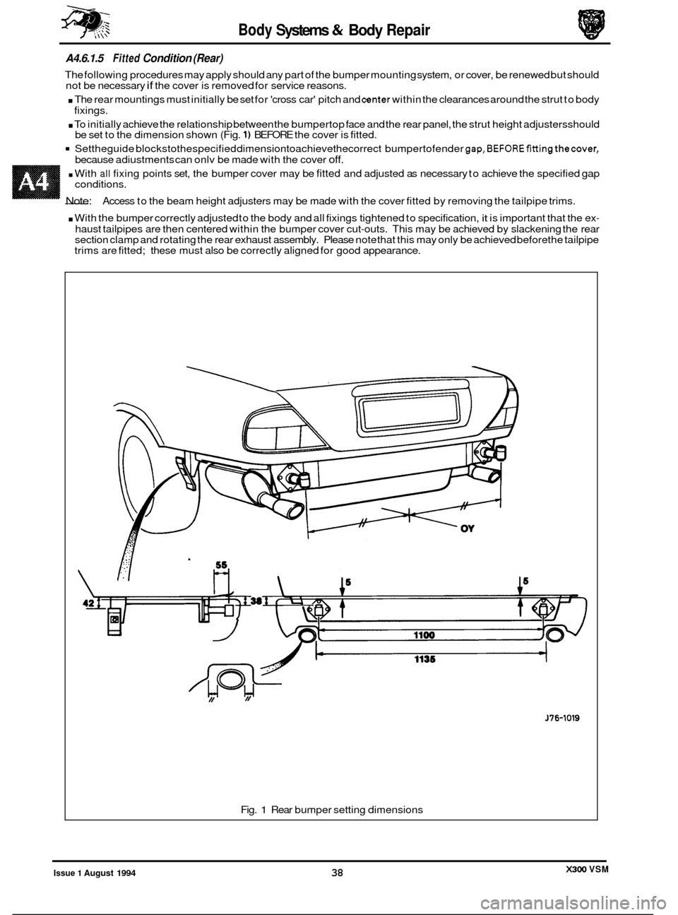
A4.6.1.5 Fitted Condition (Rear)
The following procedures may apply should any part of the bumper mounting system, or cover, be renewed but should
not be necessary if the cover is removed for service reasons.
. The rear mountings must initially be set for 'cross car' pitch and center within the clearances around the strut to body
. To initially achieve the relationship between the bumpertop face and the rear panel, the strut height adjustersshould
9 Settheguide blockstothespecified dimensiontoachievethecorrect bumpertofender gap,BEFOREfittingthecover,
fixings.
be set to the dimension shown (Fig.
1) BEFORE the cover is fitted.
because adiustments can onlv be made with the cover
off.
. With all fixing points set, the bumper cover may be fitted and adjusted as necessary to achieve the specified gap
- Note:
conditions.
Access to the beam height adjusters may be made with the cover fitted by removing the tailpipe trims.
. With the bumper correctly adjusted to the body and all fixings tightened to specification, it is important that the ex-
haust tailpipes are then centered within the bumper cover cut-outs. This may be achieved by slackening the rear
section clamp and rotating the rear exhaust assembly. Please note that this may only be achieved before the tailpipe
trims are fitted; these must also be correctly aligned for good appearance.
J76-1019
Fig. 1 Rear bumper setting dimensions
X300 VSM Issue 1 August 1994 38
Page 466 of 521

Body Systems & Body Repair
Category
Cosmetic
Substrate surface
Substrate penetration
A4.6.2 COVER DAMAGE
A4.6.2.1 Damage Assessment
Prior to any action, damage should be assessed and categorized in accordance with the following, noting that if the
cover has been 'holed' or torn, it should be discarded. The following categories are the only conditions which may
be repaired.
Damage
Abrasion to surface paint finish only
Deep scratches, gouges or localized radial stress cracks.
Splits not exceeding
100mm. Splits radiating from a gouge and
calized stress cracks.
I
CAUTION: Cosmetic appearance must not override safety.
Damage beyond category three will compromise the protective performance of the unit should repairs
be effected, the cover MUST be renewed.
Due to the thermo-setting nature of the cover material, it is NOT possible to repair splits by heat or weld- ing.
A4.6.2.2 Repair Materials
Repair of accepted damage for categories 2 and 3 may be carried out using products from;
3M '5900 FPRM' (Flexible part repair material)
Kent Industries 'Urepatch'
It is essential that the repair product manufacturer's recommendations and procedures are followed carefully.
X300 VSM
Page 467 of 521

Body Systems 4% Body Repair
A4.6.3 REFINISHING
The paint refinishing system must be approved by Jaguar Cars Ltd., and be appropriate for polyurethane substrate
application. It is important that the finishing clear lacquer includes a plasticising ingredient (mixed to the manufac-
turer's recommendation) to reflect the 'semi-flex' condition of the factory finished item.
The effect of heat decreases the cover rigidity to the point that paint
-cure temperatures require that the cover must
be supported to prevent distortion and sagging; these comments apply to 'off-car' repairs.
A4.6.3.1 Original
On an original unit where damage has been repaired, the beam will provide sufficient support for the forward part of
the unit. It is recommended that the side armatures are supported as they would be on the vehicle.
A4.6.3.2 New
Where a new cover is required, the beam may be temporarily fitted priorto painting to provide the necessary support.
A4.6.3.3 All
Asimple jig (Fig. 1)should be madeto hold the unit in thecorrect working attitude for both damage repair and refinish- ing.
CAUTION: During heat cure, the effective panel temperature must not exd 95OC.
J76-1038
Fig. 1
A4.6.4 REPLACEMENT COVERS
Replacement covers will be supplied in a primed condition and therefore must be finished in accordance with A4.6.3,
this page.
Bumper covers and replacement fixings such as bumper beam adjusters and guide blocks must be fitted and adjusted
as detailed in
A4.6.1.4 and A4.6.1.5, this section.
A4.6.5 RECYCLED
MATERIALS - GENERAL NOTE
The aluminium bumper beam, as fitted to North American specification vehicles, should not be over-looked as a com- ponent for recycling.
Side armatures will be fully assembled in replacement bumper covers, please see 'note' Recycled materials, this sec
-
tion, for important information.
Issue 1 August 1994 40
0
x300 VSM
Page 468 of 521

A4.6.6.2 Body-side Moulding - Fitfed Condition
A4.6.6 BODY-SIDE MOULDINGS
A4.6.6.1 Introduction
There are two types of moulding fitted to the standard wheelbase sedan.
The lower moulding is ‘self
-locating‘ on the body / door lower feature line and therefore provides a fixed datum for
the location of the upper moulding (wherefitted). Replacement lower mouldings will be supplied in a primed condition
and therefore must be finished in accordance with A4.6.3, this section.
Location Finish Application Fixing method
Polished stainless steel Daimler / VDP Adhesive
tape
Lower Bodv
color All models Adhesive
tape
Upper ~~
J76-la23
1 . Adhesive
tape 2. Moulding, Daimler / VDP. 3. Moulding, All models
Fig.
1
144.6.6.3 Fitting process
. ‘Spirit wipe’ appropriate body panel and where appropriate protect against damage.
. Gently warm body panel and moulding using infa-red lamp or similar.
. Lower moulding - align to body feature and other mouldings if appropriate, and secure into position.
. Upper moulding - align to lower moulding for distance (Fig. 1) and parallelism and other mouldings if appropriate,
and secure into position.
. Apply an even pressure along the moulding to fully secure to the panel.
issue 1 August 1994 41 X300 VSM
Page 469 of 521

Body Systems & Body Repair
A4.6.7 FINISHER - DOOR FRAME
//
1. Section, door frame
2. Compression cord
3. Frame finisher
Fig.
1
+
A4.6.8 FINISHER - ROOF DRIP RAIL
2
c---
J76-1037
1. Section, roof
2. Drip rail finisher assembly
3. Assembled condition
Fig.
2
Issue 1 August 1994 42 X300 VSM
Page 470 of 521

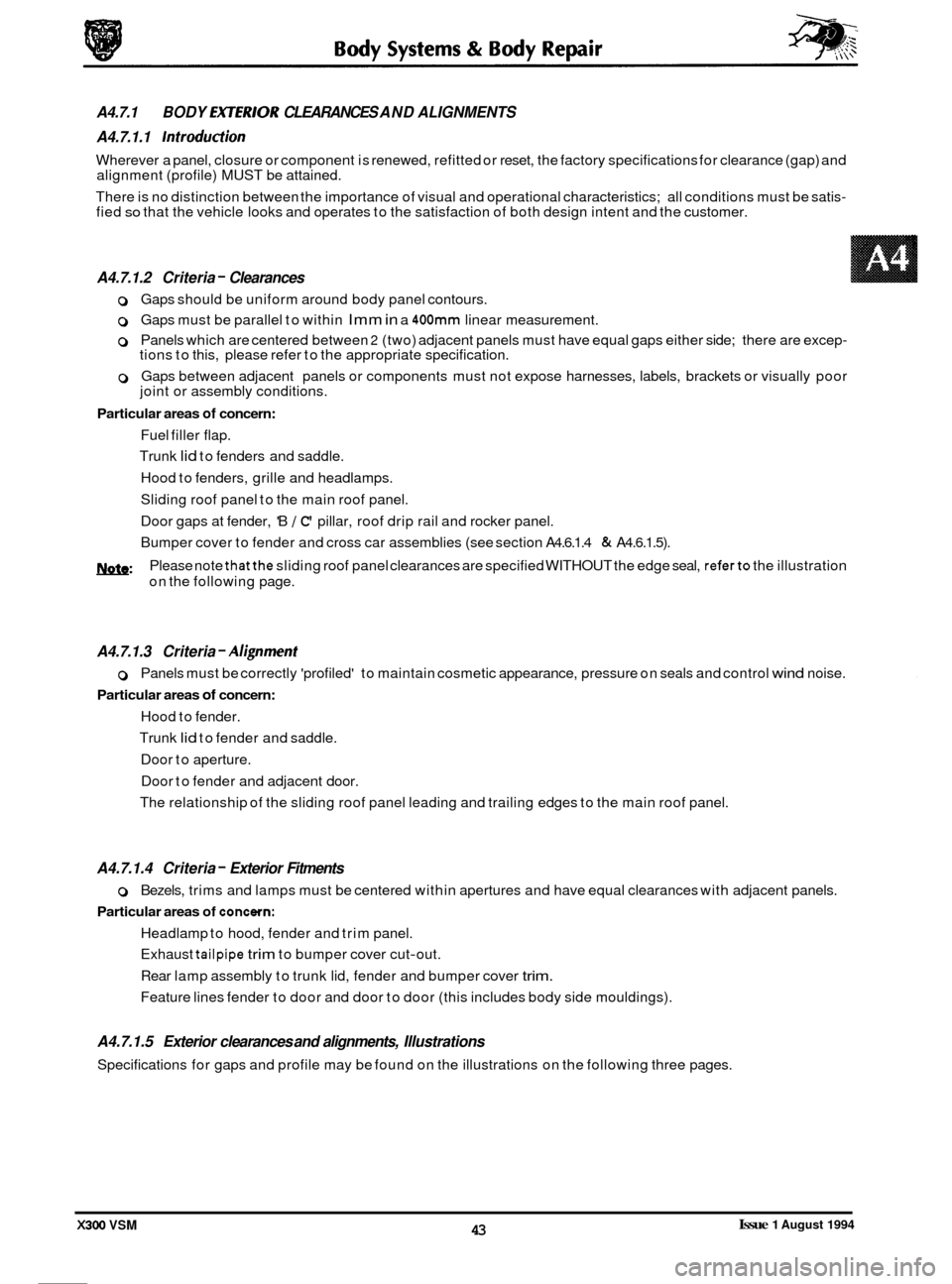
0 Gaps should be uniform around body panel contours.
0 Gaps must be parallel to within Imm in a 400mm linear measurement.
0 Panels which are centered between 2 (two) adjacent panels must have equal gaps either side; there are excep- tions to this, please refer to the appropriate specification.
0 Gaps between adjacent panels or components must not expose harnesses, labels, brackets or visually poor
joint or assembly conditions.
Particular areas of concern:
Fuel filler flap.
Trunk
lid to fenders and saddle.
Hood to fenders, grille and headlamps.
Sliding roof panel to the main roof panel.
Door gaps at fender, 'B
/ C' pillar, roof drip rail and rocker panel.
Bumper cover to fender and cross car assemblies (see section A4.6.1.4
& A4.6.1.5).
m: Please note thatthe sliding roof panel clearances are specified WITHOUT the edge seal, referto the illustration
on the following page.
A4.7.1.3 Criteria - A1;gnment
0 Panels must be correctly 'profiled' to maintain cosmetic appearance, pressure on seals and control wind noise.
Particular areas of concern:
Hood to fender.
Trunk
lid to fender and saddle.
Door to aperture.
Door to fender and adjacent door.
The relationship of the sliding roof panel leading and trailing edges to the main roof panel.
A4.7.1.4 Criteria - Exterior Fitments
Particular areas of concewn:
0 Bezels, trims and lamps must be centered within apertures and have equal clearances with adjacent panels.
Headlamp to hood, fender and trim panel.
Exhaust
tailpipe trim to bumper cover cut-out.
Rear lamp assembly to trunk lid, fender and bumper cover
trim.
Feature lines fender to door and door to door (this includes body side mouldings).
A4.7.1.5 Exterior clearances and alignments, Illustrations
Specifications for gaps and profile may be found on the illustrations on the following three pages.
A4.7.1
A4.7.1.1
Introduction
Wherever a panel, closure or component is renewed, refitted or reset, the factory specifications for clearance (gap) and
alignment (profile) MUST be attained.
There is no distinction between the importance of visual and operational characteristics; all conditions must be satis
- fied so that the vehicle looks and operates to the satisfaction of both design intent and the customer.
BODY EX7ERlOR CLEARANCES AND ALIGNMENTS
A4.7.1.2 Criteria
- Clearances
Issue 1 August 1994 43 X300 VSM