JAGUAR XJ6 1994 2.G Workshop Manual
Manufacturer: JAGUAR, Model Year: 1994, Model line: XJ6, Model: JAGUAR XJ6 1994 2.GPages: 521, PDF Size: 17.35 MB
Page 431 of 521

Body Systems & Body Repair
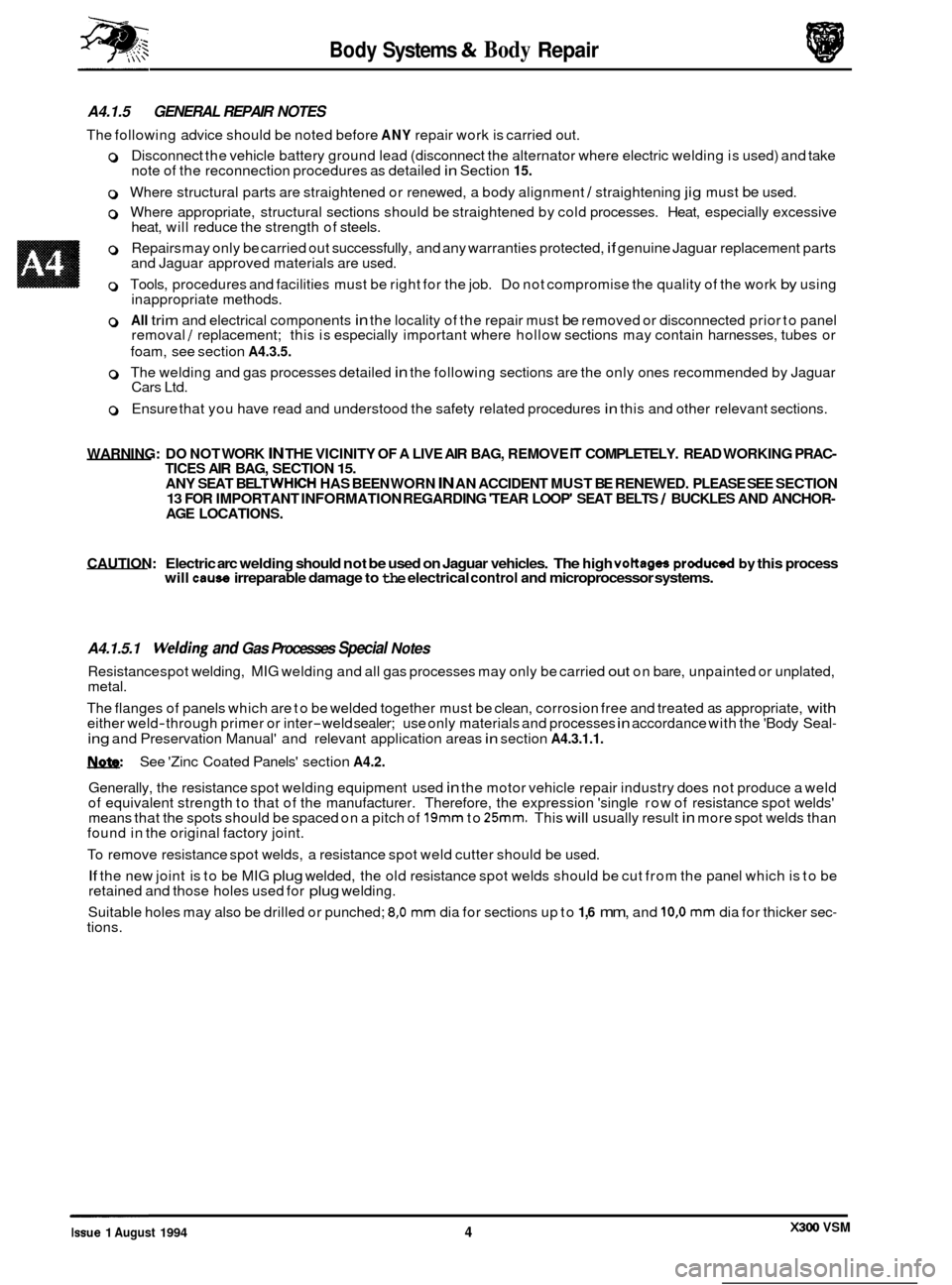
A4.1.5 GENERAL REPAIR NOTES
The following advice should be noted before ANY repair work is carried out.
0 Disconnect the vehicle battery ground lead (disconnect the alternator where electric welding is used) and take
note of the reconnection procedures as detailed in Section 15.
0 Where structural parts are straightened or renewed, a body alignment / straightening jig must be used.
0 Where appropriate, structural sections should be straightened by cold processes. Heat, especially excessive
heat, will reduce the strength of steels.
0 Repairs may only be carried out successfully, and any warranties protected, if genuine Jaguar replacement parts
and Jaguar approved materials are used.
0 Tools, procedures and facilities must be right for the job. Do not compromise the quality of the work by using
inappropriate methods.
0 All trim and electrical components in the locality of the repair must be removed or disconnected prior to panel
removal / replacement; this is especially important where hollow sections may contain harnesses, tubes or
foam, see section
A4.3.5.
0 The welding and gas processes detailed in the following sections are the only ones recommended by Jaguar
Cars Ltd.
0 Ensure that you have read and understood the safety related procedures in this and other relevant sections.
WARNING: DO NOT WORK
IN THE VICINITY OF A LIVE AIR BAG, REMOVE IT COMPLETELY. READ WORKING PRAC- TICES AIR BAG, SECTION 15. ANY SEAT BELT WHICH HAS BEEN WORN IN AN ACCIDENT MUST BE RENEWED. PLEASE SEE SECTION
AGE LOCATIONS. 13 FOR IMPORTANT INFORMATION REGARDING 'TEAR LOOP' SEAT BELTS / BUCKLES AND ANCHOR-
CAUTION: Electric arc welding should not be used on Jaguar vehicles. The high vottages produced by this process will cause irreparable damage to the electrical control and microprocessor systems.
A4.1.5.1 Welding and Gas Processes Special Notes
Resistance spot welding, MIG welding and all gas processes may only be carried out on bare, unpainted or unplated,
metal.
The flanges of panels which are to be welded together must be clean, corrosion free and treated as appropriate,
with either weld-through primer or inter-weld sealer; use only materials and processes in accordance with the 'Body Seal-
ing and Preservation Manual' and relevant application areas in section A4.3.1.1.
See 'Zinc Coated Panels' section A4.2.
Generally, the resistance spot welding equipment used in the motor vehicle repair industry does not produce a weld
of equivalent strength to that of the manufacturer. Therefore, the expression 'single row of resistance spot welds'
means that the spots should be spaced on a pitch of
19mm to 25mm. This will usually result in more spot welds than
found in the original factory joint.
To remove resistance spot welds, a resistance spot weld cutter should be used.
If the new joint is to be MIG plug welded, the old resistance spot welds should be cut from the panel which is to be
retained and those holes used for plug welding.
Suitable holes may also be drilled or punched;
8,O mm dia for sections up to 1,6 mm, and 10,O mm dia for thicker sec- tions.
0
0
0
X300 VSM Issue 1 August 1994 4
Page 432 of 521

Body Systems & Body Repair
Term
ABS
ABS
/ PA
ABS
/ PC
ABS / PBT
A#. 1.6 PLASTICS - EXPLANATORY NOTES
A#. 1.6.1 Plastic component and trim materials.
This table, in conjunction with the illustrations on the following pages will enable rapid identification of the particular
material of any major plastic part.
Material Name
Acrylonitrile Butadiene Styrene
Acrylonitrile Butadiene Styrene
& Polyamide (nylon) blend
Acrylonitrile Butadiene Styrene
& Polycarbonate blend
Acrylonitrile Styrene Acrylate
& Polybutylene Terephthalate
PC
PE
PMMA
POM
PP
PPO
PUR
PVC
SMA
I PA 1 Polyamide (nylon) I
Polycarbonate
Polyethylene
Polymethyl
Methacrylate
Polyoxymethylene (acetal)
Polypropylene
Modified Polyphenylene Oxide
Polyurethane
Polyvinylchloride
Styrene Maleic Anhydride
w: Not all plastic components are nominated, only those suitable for economic reclamation.
A#. 1.6.2 Plastics - Handling Notes
w: With reference to the following conditions, consider the properties of those plastic components which may
be affected by a repair or rectification procedure.
0 As mentioned elsewhere, the exterior panel temperature of the vehicle must not exceed 95OC at any time and
may only be held at this upper limit for a maximum of 2 (two) hours.
0 Interior vehicle temperature must not exceed 86OC, the time limit being 2 (two) hours.
0 Temperatures above those specified in 1 and 2, may result in distorted or permanently damaged components. If there is any doubt whatsoever, remove those components which may be affected by the application of heat.
0 Certain items may be manufactured from 'blended' materials; these must NOT be recycled with pure materials.
For example do not mix PC/ABS (wheel trim) with ABS ('B' pillar upper trim).
0 Should plastic components become greasy, they may be cleaned with an 'SBP 3' spirit wipe, or equivalent.
A4.1.6.3 Recycled Materials
Any of the materials listed in A4.1.6.1 may be recycled provided that they are not contaminated by other incompatible
plastics or metals. For instance, the air conditioning unit case, manufactured from PP (polypropylene), must be separ- ated from the heater matrix, evaporator, control devices (electronic and mechanical) and all fixings before it can be
considered for recycling.
After disassembly, the case must be placed for disposal only
with materials of the same generic type.
w: The bumper cover assemblies have side armatures (non-eerviceable items) rivetted to them; because they
are dissimilar materials the armatures and fixings must be removed prior to recycling.
In the bumper cover intake aperture there is a cosmetic 'black-out' piece; a similar component may be found
on the fog lamp blanks (where fitted). These items should be separated from the major component for recycl- ing.
Issue 1 August 1994 5 X300 VSM
Page 433 of 521

a- P
Body Systems & Body Repair
6 0
0
0
Page 434 of 521

0
0
0
A4.1.6.5 PlasticS, Component location & Type - lntemal
n. n.
Issue 1 August 1994 7 X300 VSM
Page 435 of 521

P
X300 VSM issue 1 August 1994 8
Page 436 of 521

Body Systems
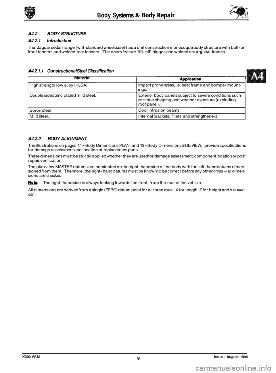
A4.2.1.1 Constructional Steel Classification
Material 1 dnnlirdiam I
High strength low alloy (HLSA).
Double sided zinc plated mild steel.
1 Boron steel
1 Mild steel.
A4.2.2 BODY ALIGNMENT
The illustrations on pages 11 - Body Dimensions PLAN, and 13 -Body Dimensions SIDE VIEW, provide specifications
for damage assessment and location of replacement parts.
These dimensions must be strictly applied whether they are used for damage assessment, component location or post
repair verification.
The plan view MASTER datums are nominated on the right
-hand side of the body with the left-hand datums dimen- sioned from them. Therefore, the right-hand datums must be known to be correct before any other cross-ar dimen- sions are checked.
W: The right-hand side is always looking towards the front, from the rear of the vehicle.
All dimensions are derived from a single
(ZERO) datum point for all three axes; X for length, Z for height and V cross- car.
Issue 1 August 1994 9 X300 VSM
A4.2 BODY STRUCTURE
A4.2.1
Introduction
The Jaguar sedan range (with standard wheelbase) has a unit construction monocoque body structure with bolt-on
front fenders and welded rear fenders. The doors feature 'lift-off' hinges and welded dropglass frames.
n@#pn.s..v..
Impact prone areas, ie. seat frame and bumper mount- ings.
Exterior body panels subject to severe conditions such
as stone chipping and weather exposure (excluding
roof panel).
Door intrusion beams
Internal brackets, fillets and strengtheners.
I
Page 437 of 521

Body Systems & Body Repair
Location
Centre line of the front crossmember rear mounting, at the
main floor
RH longitudinal
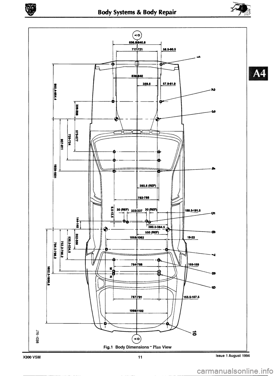
A4.2.2.1 Datum location, Example
The FRONT MASTER DATUM (front crossmember rear mounting at the inner face ofthe main floor RH longitudi- nal) is nominally 359,5mm to the right-hand side of the body center line. The LH side front datum is measured 717,0/ 721,Omm from the RH. Please refer to the illustration on the following page.
Expressed as
a true position in three planes, the front master datum is:
Position
X 300,O
Y 359.5 Z -50.0
0
Datum
Front Master Datum
Plan
A4.2.2.2 Key, Plan View
Please refer to the illustration on the opposite page.
Key Location
1
2
3
4
5 Driveshaft centre bearing fixings
6
7
8
9
10 Front
face body
- bumper strut / mounting point
Rearmost hole, Vee
-mount to crush tube
Front Master Datum Plan, centre line
of the front crossmember rear mounting at the main floor RH longi-
tudinal
Rearmost hole, transmission mounting
at the main floor RH longitudinal
Rear Master Datum Plan, rear longitudinal
Tapped boss, rear suspension
'A' frame mounting bush
Rear suspension spring
-pan damper mounting
Rear suspension differential strut mounting
Rear face body
- bumper strut / mounting point
X300 VSM Issue 1 August 1994 10
Page 438 of 521

0
0
0
-
0
w
tn
Q)
OD
Fig.1 Body Dimensions - Plan View
Issue 1 August 1994 X300 VSM 11
Page 439 of 521

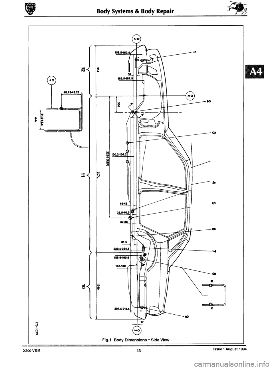
E 12
Rear face bodv - bumDer strut / mountina Doint
Body Systems
I
& Body
side vww
the illustration on the opposite page.
Repair
Location
Front face body - bumper strut / mounting point
Front Master Datum Vertical. centre line of the front crossmember rear mountina
Front
face body - bumper strut / mounting point
Front Master Datum Vertical, centre line of the front crossmember rear mounting
Transmission mountings
at the main floor longitudinal
Driveshaft centre bearing fixings
Rear Master Datum
Vertical, rear longitudinal
Tapped boss, rear suspension
'A' frame mounting bush
Rear suspension spring
-pan damper mounting
Rear suspension differential strut mounting
Rear face body
- bumper strut / mounting point
Transmission
mountings
at the main floor longitudinal
Driveshaft centre bearing fixings
Rear Master Datum
Vertical, rear longitudinal
Tapped boss, rear suspension
'A' frame mounting bush
Rear suspension spring
-pan damper mounting
Rear
susoension differential strut mounting
Wheel centre to
bummr cover face I
Wheel base I
Wheel centre to bumper cover face
Body Systems & Body Repair
A4.2.2.3 Key, Side Vww
Please refer to the illustration on the opposite page.
0
0
0
X300 VSM Issue 1 August 1994 12
Page 440 of 521

0
0
0
-
0
v 3
I so 185.5-187.!
t
4
230.5-234.5
i:: cn
I m
8
Fig.1 Body Dimensions - Side View
Issue 1 August 1994 X300 VSM 13