engine coolant JAGUAR XJ6 1994 2.G Workshop Manual
[x] Cancel search | Manufacturer: JAGUAR, Model Year: 1994, Model line: XJ6, Model: JAGUAR XJ6 1994 2.GPages: 521, PDF Size: 17.35 MB
Page 11 of 521
Introduction
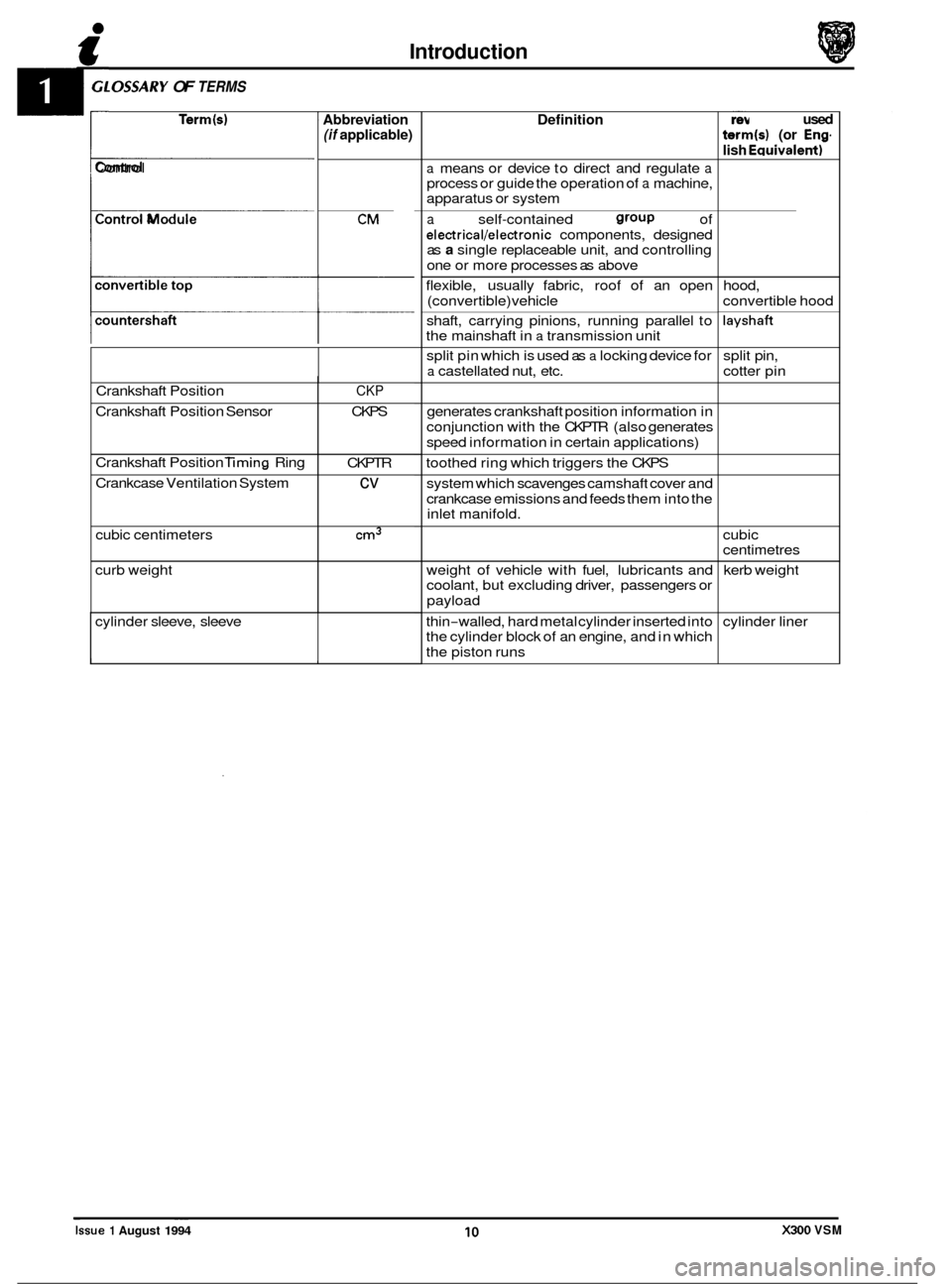
.OSSARY OF TERMS
Term(s)
Crankshaft Position
Crankshaft Position Sensor
Crankshaft Position
liming Ring
Crankcase Ventilation System
cubic centimeters
curb weight
4 Control
CKP
CKPS
CKPTR
cv
cm3
Control Module
P
T Abbreviation (if applicable)
CM
cylinder sleeve, sleeve
I I
Definition
a means or device to direct and regulate a process or guide the operation of a machine,
apparatus or system
a self-contained group of
electrical/electronic components, designed
as a single replaceable unit, and controlling
one or more processes as above
flexible, usually fabric, roof of an open
(convertible) vehicle
shaft, carrying pinions, running parallel to
the mainshaft in
a transmission unit
split pin which is used as
a locking device for
a castellated nut, etc.
generates crankshaft position information in
conjunction with the CKPTR (also generates
speed information in certain applications)
toothed ring which triggers the CKPS
system which scavenges camshaft cover and
crankcase emissions and feeds them into the
inlet manifold.
weight of vehicle with fuel, lubricants and
coolant, but excluding driver, passengers or
payload
thin
-walled, hard metal cylinder inserted into
the cylinder block of an engine, and in which
the piston runs
Previously used
term(s) (or Eng.
lish Eauivalent)
hood,
convertible hood
layshaft
split pin,
cotter pin
cubic
centimetres kerb weight
cylinder liner ~ ~~
Issue 1 August 1994 10 X300 VSM
Page 12 of 521
Introduction
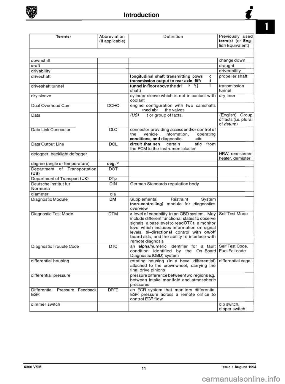
Term(s) Abbreviation Definition
(if applicable) Previously
used term(s) (or Eng-
lish Equivalent)
downshift
draft _.
drivability
driveshaft
driveshaft tunnel
dry sleeve
Dual Overhead Cam
Data
Data Link Connector
Data Output Line
defogger, backlight defogger
degree (angle or temperature)
Department of Transportation
(US)
Department of Transport (UK)
Deutsche lnstitut fur
Normuna
diameter
Diagnostic Module
Diagnostic Test Mode
Diagnostic Trouble Code
differential housing
differentia
I pressure
Differential Pressure Feedback
EGR
dimmer switch DOHC
DLC
DOL
deg, O
DOT
DTP DIN dia
DM
DTM
DTC
DPFE longitudinal
shaft transmitting power from
transmission output to rear axle differential
tunnel
in floor above the driveshaft (propeller
shaft)
cylinder sleeve which is not in contact with
coolant
engine configuration with two camshafts
positioned above the valves
(US) Fact or group of facts.
connector providing access
andlor control of
the vehicle information, operating
conditions, and diagnostic information
circuit that sends certain information from
the PCM to the instrument cluster
German Standards regulation body
Supplemental Restraint System
(non-controlling) module for diagnostics
overview
a level of capability in an OBD system. May
include different functional states
to observe
signals, a base level to read
DTCs, a monitor
level which includes information on signal
levels,
bi-directional control with onloff board aids, and the ability to interface with
remote diagnosis
an
alphahumeric identifier for a fault
condition identified by the On
-Board
Diagnostic
(OBD) system
rotating housing
(in a bevel differential)
attached to the crownwheel, carrying the
final drive pinions
pressure difference between two regions e.g.
between intake manifold and atmospheric
pressures
an EGR system that monitors differential
EGR pressure across a remote orifice
to control EGR flow change
down
draught
driveability
propeller shaft
transmission
tunnel
dry liner
(English) Group
of facts (i.e. plural
of
datum)
HRW, rear screen
heater, demister
Self Test Mode
Self Test Code.
Fuel Fail code
differential cage
dip switch,
dipper switch
Issue 1 August 1994 11 X300 VSM
Page 14 of 521
Introduction c
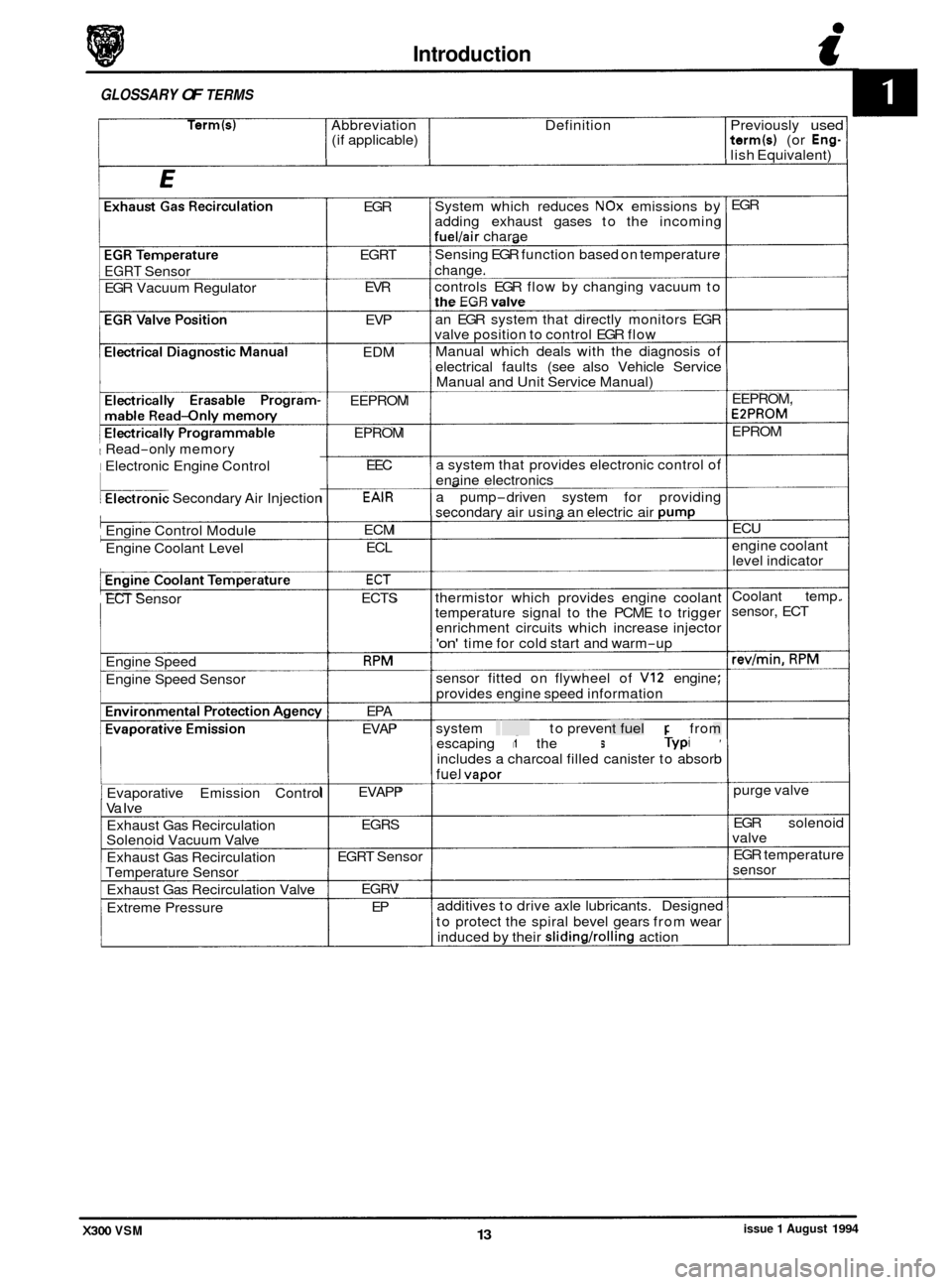
GLOSSARY OF TERMS
Term(s) Abbreviation Definition Previously used (if applicable) term(s) (or Eng- lish Equivalent)
0
EGRT Sensor
EGR Vacuum Regulator
1 Read-only memory
I Electronic Engine Control
kronic Secondary Air Injection
Engine Control Module
Engine Coolant Level
ECT Sensor
Engine Speed
Engine Speed Sensor
1 Evaporative Emission Control
Va Ive
Exhaust Gas Recirculation
Solenoid Vacuum Valve
Exhaust Gas Recirculation
Temperature Sensor
Exhaust Gas Recirculation Valve
Extreme Pressure EGR
EGRT EVR
EVP
EDM
EEPROM EPROM EEC
EAlR
ECM ECL
ECT
ECTS
RPM
EPA
EVAP
EVAPP EGRS
EGRT Sensor
EGRV EP System
which reduces
NOx emissions by
adding exhaust gases to the incoming
fuel/air charae
Sensing EGR function based on temperature
change.
controls EGR flow by changing vacuum to
the EGR valve
an EGR system that directly monitors EGR
valve position to control EGR flow
Manual which deals with the diagnosis of
electrical faults (see also Vehicle Service
Manual and Unit Service Manual)
a system that provides electronic control of
enaine electronics
a pump
-driven system for providing
secondarv air usina an electric air Dump
thermistor which provides engine coolant
temperature signal to the PCME to trigger
enrichment circuits which increase injector
'on' time for cold start and warm-up
sensor fitted on flywheel of
VI2 engine;
provides engine speed information
system designed to prevent fuel vapor from
escaping into the atmosphere. Typically
includes a charcoal filled canister to absorb
fuel
vaoor
additives to drive axle lubricants. Designed
to protect the spiral bevel gears from wear
induced by their
slidingholling action EGR
EEPROM,
EPPROM
EPROM ECU
engine coolant level indicator
Coolant temp.
sensor, ECT
revlmin. RPM
purge valve
EGR solenoid
valve
EGR temperature
sensor
X300 VSM issue 1 August 1994 13
Page 23 of 521
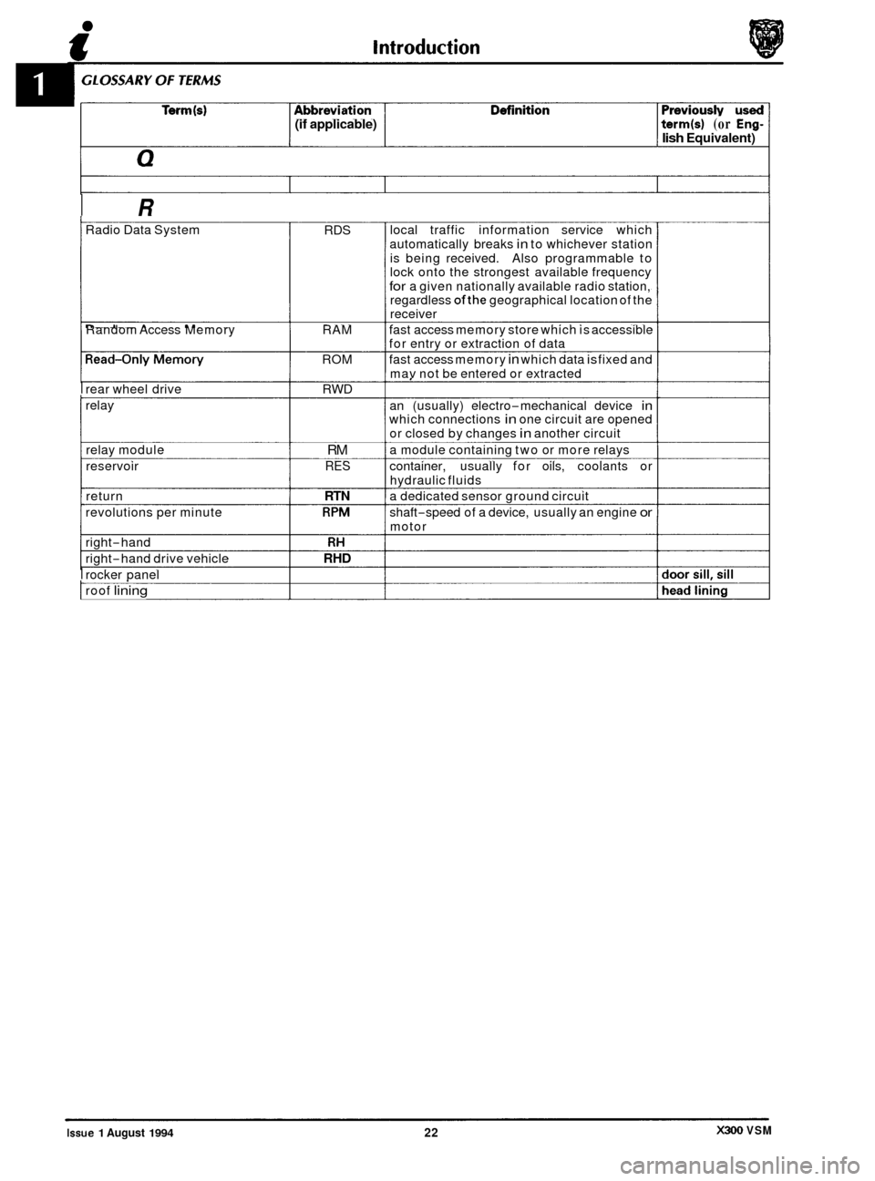
(if applicable) term(s) (or Eng- lish Equivalent)
I R
Radio Data System
Random Access Memory
I rear wheel drive
relay
relay module
reservoir
return
revolutions per minute
right
-hand
right
-hand drive vehicle
I rocker panel
I roof lining
RDS
RAM
ROM RWD
RM
RES
RTN
RPM
RH
RHD
local traffic information service which
automatically breaks
in to whichever station
is being received. Also programmable to
lock onto the strongest available frequency
for a given nationally available radio station,
regardless ofthe geographical location of the
receiver
fast access memory store which is accessible
for entry or extraction of data
fast access memory
in which data is fixed and
mav not be entered or extracted
an (usually) electro
-mechanical device in which connections in one circuit are opened
or closed by changes
in another circuit
a module containing two or more relays
container, usually for oils, coolants or
hydraulic fluids
a dedicated sensor ground circuit
shaft
-speed of a device, usually an engine or
motor
I
X300 VSM Issue 1 August 1994 22
Page 43 of 521
Engine (AJ16)
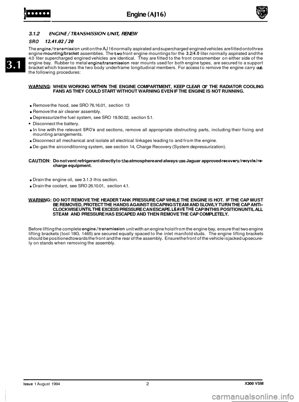
3.1.2 ENGlNE/ TRANSMlSSlON UN/& RENEW
SRO 12.41.02/20
The engine/transmission unit on the AJ 16 normally aspirated and supercharged engined vehicles are fitted ontothree
engine mounting/bracket assemblies. The two front engine mountings for the 3.2/4.0 liter normally aspirated and the
4.0 liter supercharged engined vehicles are identical. They are fitted to the front crossmember on either side of the
engine bay. Rubber to metal
engine/transmission rear mounts used for both engine types, are secured to a support
bracket which traverses the two body underframe longitudinal members. For access to remove the engine carry out the following procedures:
WARNING: WHEN WORKING WlTHlN THE ENGINE COMPARTMENT, KEEP CLEAR OF THE RADIATOR COOLING
FANS AS THEY COULD START WITHOUT WARNING EVEN IF THE ENGINE IS NOT RUNNING.
. Remove the hood, see SRO 76.16.01, section 13
. Remove the air cleaner assembly.
. Depressurize the fuel system, see SRO 19.50.02, section 5.1.
Disconnect the battery.
. In line with the relevant SRO's and sections, remove all appropriate obstructing parts, including their fixing and
. Disconnect all mechanical and isolate all electrical linkages leading to and from the engine.
. De-gas the airconditioning system, see section 14, Charge Recovery (System depressurization).
mounting
arrangements.
CAUTION : Do not vent refrigerant directly to the atmosphere and always use Jaguar approved recovery/recycle/re- charge equipment.
. Drain the engine oil, see 3.1.3 this section.
. Drain the coolant, see SRO 26.10.01, section 4.1.
WARNING: DO NOT REMOVE THE HEADER TANK PRESSURE CAP WHILE THE ENGINE IS HOT. IF THE CAP MUST
BE REMOVED, PROTECT THE HANDS AGAINST ESCAPING STEAM AND SLOWLY TURN THE CAP ANTI- CLOCKWISE UNTILTHE EXCESS PRESSURE CAN ESCAPE. LEAVETHE CAP IN THIS POSITION UNTIL ALL
STEAM AND PRESSURE HAS ESCAPED AND THEN REMOVE THE CAP COMPLETELY.
Before lifting the complete engine/transmission unit with an engine hoist from the engine bay, ensure that two engine
lifting brackets (tool 18G. 1465) are secured equally spaced to the inlet manifold studs. The engine lifting brackets
should be positioned towards the front and the rear of the assembly. Ensure the front of the vehicle is jacked
up secure- ly on stands when removing the assembly.
e
0
0
X300 VSM Issue 1 August 1994 2
Page 49 of 521
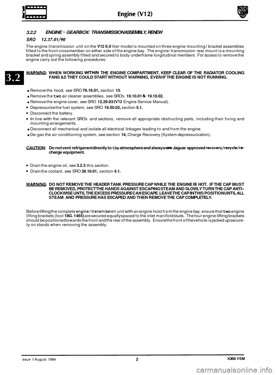
3.2.2 ENGINE - GEARBOX/ TRANSMISSION
ASSEMBLY, RENEW
SRO 12.37.01/90
The engine /transmission unit on the V12 6.0 liter model is mounted on three engine mounting / bracket assemblies
fitted to the front crossmember on either side of the engine bay. The engine/ transmission rear mount is a mounting
bracket and spring assembly fitted and secured to body underframe longitudinal members. For access to remove the
engine carry
out the following procedures:
WARNING: WHEN WORKING WITHIN THE ENGINE COMPARTMENT, KEEP CLEAR OF THE RADIATOR COOLING
FANS AS THEY COULD START WITHOUT WARNING, EVEN IF THE ENGINE IS NOT RUNNING.
. Remove the hood, see SRO 76.16.01, section 13.
. Remove the two air cleaner assemblies, see SRO’s 19.10.01 & 19.10.02.
. Remove the engine cover, see SRO 12.29.93 (V12 Engine Service Manual).
Depressurize the fuel system, see SRO 19.50.02, section 5.1.
In line with the relevant SRO’s and sections, remove all appropriate obstructing parts, including their fixing and
. Disconnect all mechanical and isolate all electrical linkages leading to and from the engine.
. De-gas the air conditioning system, see section 14, Charge Recovery (System depressurization).
Disconnect
the battery.
mounting arrangements.
CAUTION: Do
not vent refrigerant directly to the atmosphere and always use Jaguar approved recovery/recycle/ra charge equipment.
Drain the engine oil, see 3.2.3 this section.
Drain the coolant, see SRO 26.10.01, section 4.1.
WARNING: DO NOT REMOVE THE HEADER TANK PRESSURE CAP WHILE THE ENGINE IS HOT. IF THE CAP MUST
BE REMOVED, PROTECT THE HANDS AGAINST ESCAPING STEAM AND SLOWLY TURN THE CAP ANTI- CLOCKWISE UNTIL THE EXCESS PRESSURE CAN ESCAPE. LEAVE THE CAP IN THIS POSITION UNTIL ALL
STEAM AND PRESSURE HAS ESCAPED AND THEN REMOVE THE CAP COMPLETELY.
Before
lifting the complete engine/transmission unit with an engine hoist from the engine bay, ensure that two engine
lifting brackets (tool 18G. 1465) are secured equallyspaced to the inlet manifold studs. The four engine lifting brackets
should be positioned towards the front and the rear of the assembly. Ensure the front of thevehicle is jacked
up secure- ly on stands when removing the assembly.
X300 VSM Issue 1 August 1994 2
Page 54 of 521
Cooling System
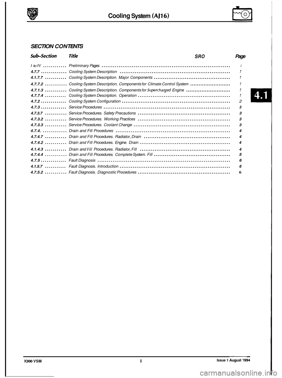
SECTION CON TENTS
Sub-section Title SRO Page
I to IV ............ Preliminary Pages .................................................................... i
4.7.7 ............. Cooling System Description ........................................................... 7
4.1.7.7 ........... Cooling System Description. Major Components .......................................... 7
4.7.7.2 ........... Cooling System Description. Components for Climate Control System ........................ 7
4.7.1.3 ........... Cooling System Description. Components for Superchargwl Engine .......................... 7
4.7.7.4 ........... Cooling System Description. Operation .................................................. 7
4.7.2 ............. Cooling System Configuration .......................................................... 2
4.7.3 ............. Service Procedures ................................................................... 3
4.7.3.7 ........... Service Procedures. Safety Precautions .................................................. 3
4.7.3.2
........... Service Procedures. Working Practices .................................................. 3
4.7.3.3
........... Service Procedures. Coolant Change .................................................... 3
4.7.4.
............ Drain and Fill Procedures ............................................................. 4
4.7.4.7
........... Drain and Fill Procedures. Radiator, Drain ............................................... 4
4.7.4.2
........... Drain and Fill Procedures. Engine. Drain ................................................. 4
4.1.4.3
........... Drain and Fill Procedures. Radiator, Fill ................................................. 4
4.7.4.4
........... Drain and Fill Procedures. Complete System. Fill .......................................... 5
4.7.5 ............. Fault Diagnosis ...................................................................... 6
4.1.5.7 ........... Fault Diagnosis. Introduction ........................................................... 6
4.7.5.2 ........... Fault Diagnosis. Diagnostic Procedures .................................................. 6
Issue 1 August 19! X300 VSM i
Page 55 of 521
€3 Cooling System (AJ16)
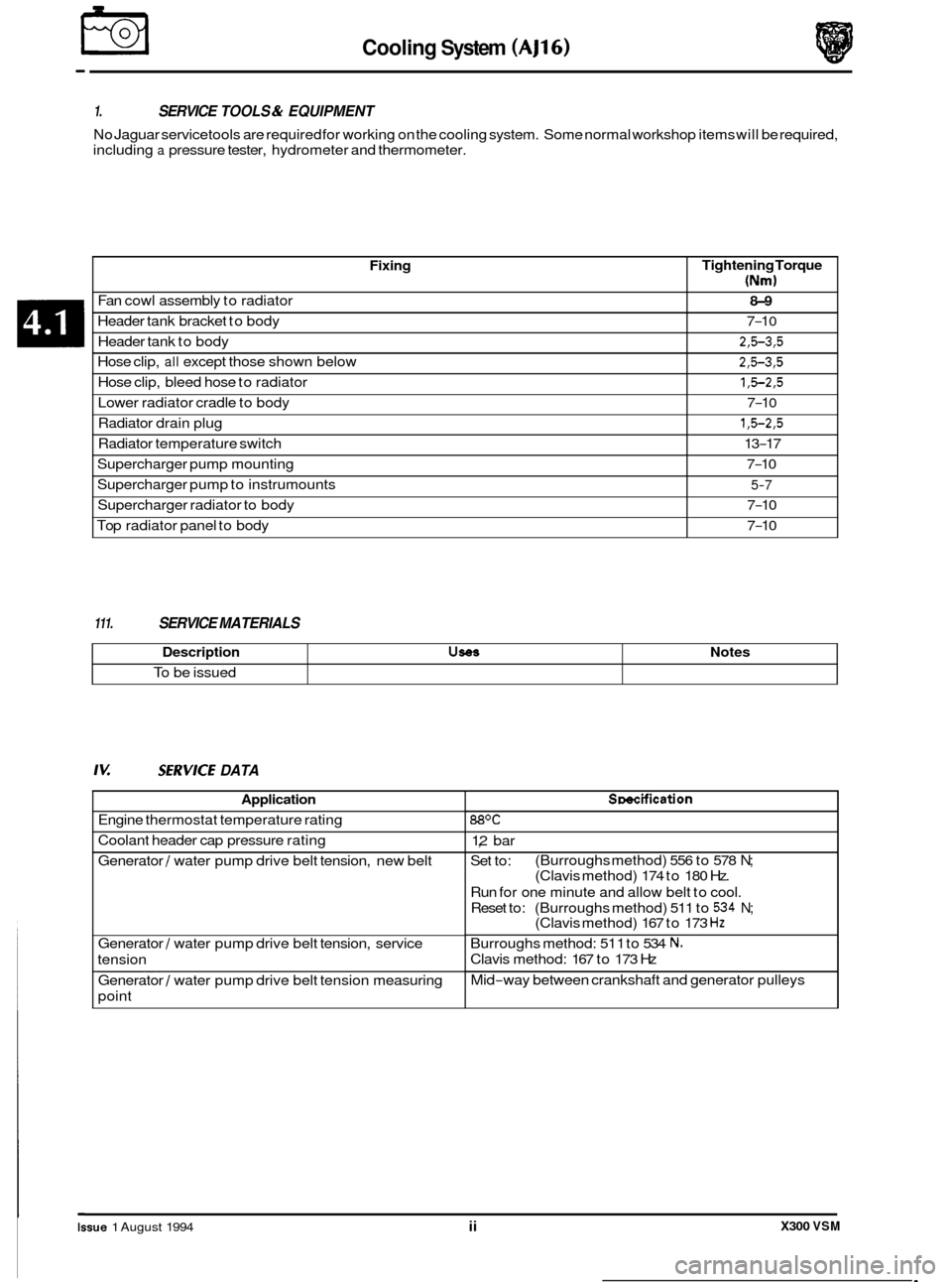
Fixing
Fan cowl assembly to radiator
Header tank bracket to body
Header tank to body
Hose clip,
all except those shown below
Hose clip, bleed hose to radiator
Radiator drain plug
Radiator temperature switch
Lower
radiator cradle to body
Supercharger pump mounting
Supercharger pump to instrumounts
Supercharger radiator to body
Top radiator panel to body
1. SERVICE TOOLS & EQUIPMENT
No Jaguar service tools are required for working on the cooling system. Some normal workshop items will be required,
including
a pressure tester, hydrometer and thermometer.
Tightening Torque
(Nm)
8-9
7-1 0
2,5-3,5
2,5-3,5
1,5-2,5
1,5-2,5
13-17
7
-1 0
7-10
5-7
7-10
7
-10
Description UseS
To be issued
111. SERVICE MATERIALS
Notes
Iv: SZRVICE DATA
Application
Engine thermostat temperature rating
Coolant header cap pressure rating
Generator
/ water pump drive belt tension, new belt
Generator
/ water pump drive belt tension, service
tension
_____ ~~ Generator / water
pump drive belt tension measuring
point
Smcification
88OC
1,2 bar
Set to:
Run for one minute and allow belt to cool.
Reset to: (Burroughs method) 511 to
534 N;
Burroughs method: 51 1 to 534 N.
Clavis method: 167 to 173 Hz
Mid
-way between crankshaft and generator pulleys
(Burroughs method)
556 to 578
N;
(Clavis method) 174 to 180 Hz.
(Clavis method) 167 to 173
Hz
0
0
0
0
X300 VSM Issue 1 August 1994 ii
Page 56 of 521
Cooling System (AJl6) m
4.1.1 COOLING SYSTEM DESCRIPTION
4.1.1.1 Major Components
o Main engine crossflow radiator, incorporating a concentric tube cooler for the power steering fluid mounted in
the right
-hand radiator side tank. Vehicles with automatic transmission have a transmission fluid cooler
mounted in the left
-hand radiator side tank; for 4,O liter supercharged engines a six-plate cooler is fitted; other
vehicles have
a tube-type cooler. Adouble-action temperature switch, for controlling the radiator cooling fans,
is mounted in the left
-hand radiator side tank.
0 Two electrically operated radiator cooling fans, mounted behind the main radiator.
0 Coolant circulating pump, belt driven from the engine crankshaft.
0 Coolant header tank with pressure relief cap and coolant level probe.
o Engine thermostat.
4.1.1.2
0 Heater matrix.
o Electrically operated coolant circulating pump, mounted on the left-hand side of the engine bulkhead.
o Solenoid operated valve, located adjacent to the coolant circulating pump.
Components for Climate Control System
4.1.1.3 Components for Supercharged Engine
0 0 Supercharger crossflow radiator, mounted in front of the main radiator. The supercharger radiator is reverse- circuited, i.e. the coolant inlet is at the bottom of the radiator.
0 Electrically operated coolant circulating pump, located at the left-hand side of the main radiator.
4.1.1.4 Operation
The configuration of the cooling system for normally aspirated and supercharged (4,O liter) engines is shown in Sub- section 4.1.2.
The cooling system is pressurized, which allows the system to operate at a higher temperature without overheating.
The header tank is fitted with a pressure relief cap to protect the system against overpressure.
Under cold start conditions, coolant is forced by the engine driven water pump through the cylinder block and cylinder
head to the thermostat housing. The thermostat is closed to give rapid engine warm up, hence the coolant is returned
directly to the water pump inlet. When normal engine operating temperature is reached, the thermostat opens and
coolant is diverted through the radiator before returning to the water pump inlet. In vehicles fitted with
a supercharger,
coolant is circulated through the supercharger radiator and intercooler by the supercharger water pump. The super- charger cooling circuit uses the same coolant header tank as the main engine cooling system.
The radiator cooling fans operate in series and parallel under the control of the double
-action radiator mounted tem- perature switch. The fans are also controlled by the climate control system on vehicles fitted with air conditioning.
Under hot operating conditions, the fans may continue to operate after the engine has been switched off. The fans
stop automatically when the coolant temperature has been reduced sufficiently.
The system also provides the coolant supply for the climate control system, which is described in Section
14.
X300 VSM 1 Issue 1 August 1994
Page 57 of 521
€3 Cooling System (AJ16)
4.1.2 COOLING SYSTEM CONFIGURATION
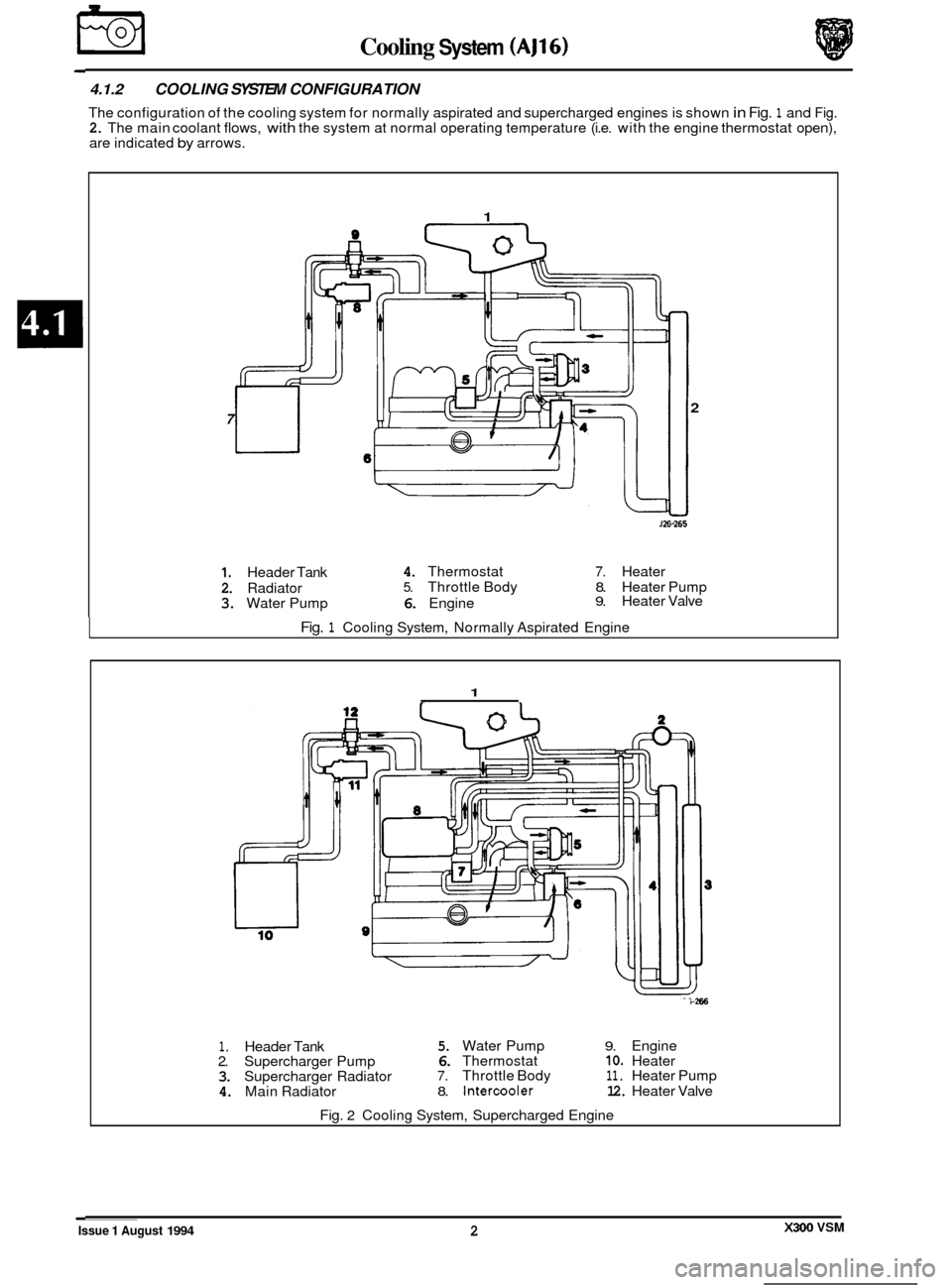
The configuration of the cooling system for normally aspirated and supercharged engines is shown in Fig. 1 and Fig. 2. The main coolant flows, with the system at normal operating temperature (i.e. with the engine thermostat open),
are indicated by arrows.
1
2 7
J26-265
1. Header Tank 4. Thermostat 7. Heater
2. Radiator 5. Throttle Body 8. Heater Pump
3. Water Pump 6. Engine 9. Heater Valve
Fig. 1 Cooling System, Normally Aspirated Engine
1
i-266
1. Header Tank 5. Water Pump 9. Engine
2. Supercharger Pump 6. Thermostat IO. Heater
3. Supercharger Radiator 7. Throttle Body 11. Heater Pump
4. Main Radiator 8. Intercooler 12. Heater Valve
Fig.
2 Cooling System, Supercharged Engine
Issue 1 August 1994 X300 VSM 2