mirror controls JAGUAR XJ6 1994 2.G Workshop Manual
[x] Cancel search | Manufacturer: JAGUAR, Model Year: 1994, Model line: XJ6, Model: JAGUAR XJ6 1994 2.GPages: 521, PDF Size: 17.35 MB
Page 10 of 521

Introduction i
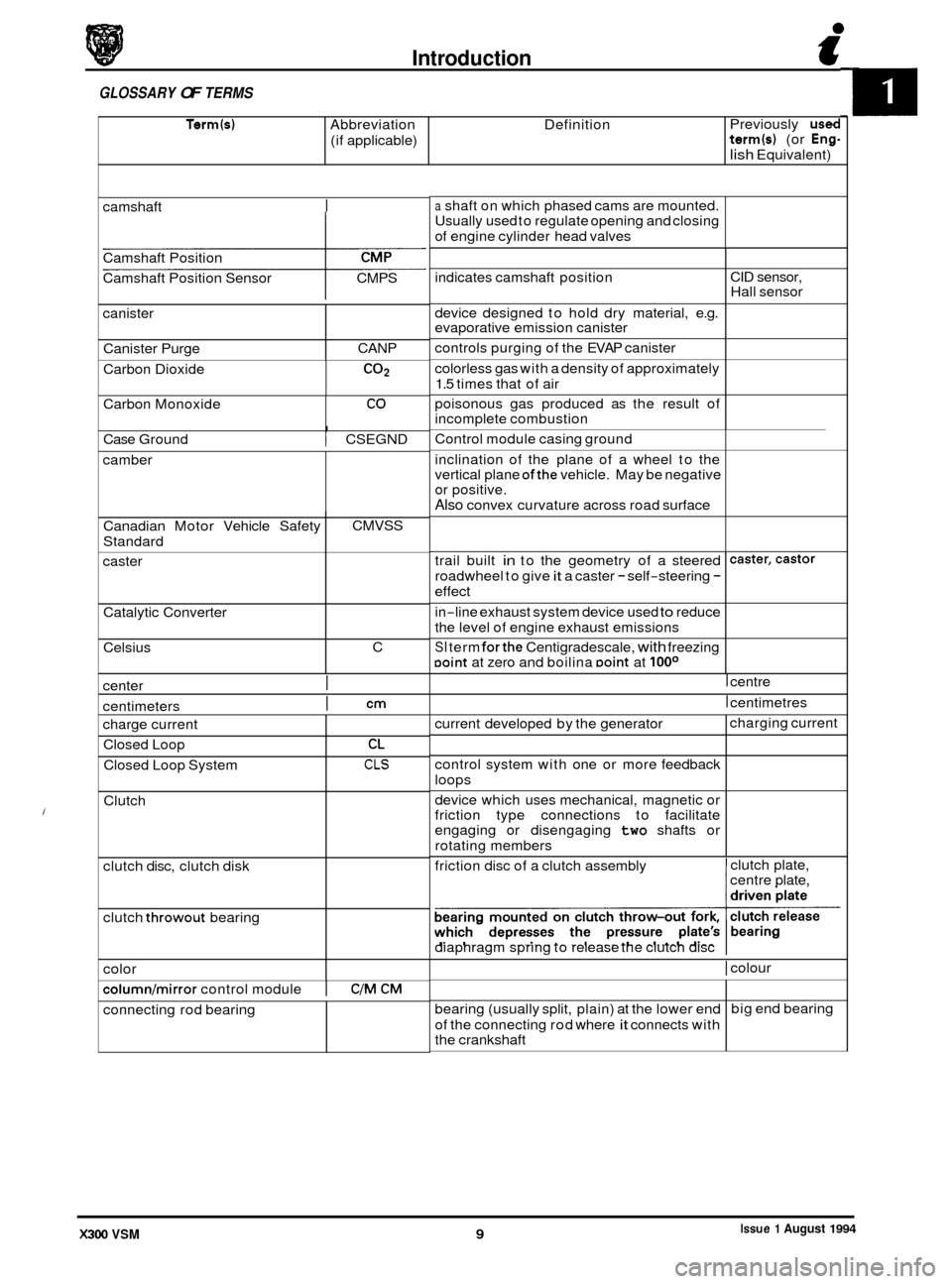
Term(s) Abbreviation Definition
(if applicable)
GLOSSARY OF TERMS
Previously used term(s) (or Eng-
lish Equivalent)
indicates camshaft position
device designed to hold dry material, e.g.
evaporative emission canister
controls purging of the EVAP canister
colorless gas with a density of approximately
1.5 times that of air
poisonous gas produced as the result of
incomplete combustion
camshaft
I
CID
sensor,
Hall sensor
Camshaft
Position
Camshaft Position Sensor CMPS
canister
Canister Purge CANP
Carbon Dioxide
CO2
I Case Ground I CSEGND
Carbon
Monoxide
camber
CO
Canadian Motor Vehicle Safety
Standard
caster
Catalytic Converter
Celsius
center
I
CMVSS
C
centimeters
I cm
trail built in to the geometry of a steered
roadwheel to give
it a caster - self-steering -
effect
caster,castor
color
columnlmirror control module I C/M CM
charge current
Closed Loop
Closed Loop System
Clutch
clutch disc, clutch disk
clutch
throwout bearing
connecting rod bearing
CL
CLS
a shaft on which phased cams are mounted.
Usually used to regulate opening and closing
of engine cylinder head valves
current developed by the generator
control system with one or more feedback
loops
device which uses mechanical, magnetic or
friction type connections to facilitate
engaging or disengaging
two shafts or
rotating members charging
current
Control
module casing ground
inclination of the plane of a wheel to the
vertical plane
ofthe vehicle. May be negative
or positive.
Also convex curvature across road surface
bearing (usually split, plain) at the lower end
of the connecting rod where
it connects with
the crankshaft big
end bearing
in
-line exhaust
system device used to reduce
the level of engine exhaust emissions
SI term forthe Centigradescale, with freezing Doint at zero and boilina Doint at looo
I centre
I centimetres
friction disc of a clutch assembly clutch
plate,
centre plate,
diaphragm spring to release the clutch disc
I colour
Issue 1 August 1994 X300 VSM 9
Page 318 of 521

Climate Control Systems
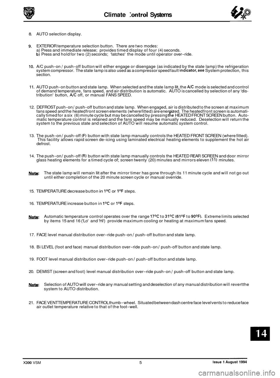
8. AUTO selection display.
9. EXTERIOR temperature selection button. There are two modes:
a) Press and immediate release; provides timed display of four (4) seconds.
b) Press and hold for two (2) seconds; 'latches' the mode until operator over-ride.
10. A/C push-on / push-off button will either engage or disengage (as indicated by the state lamp) the refrigeration
system compressor. The state lamp is also used as a compressor speed fault indicator,see System protection, this
section.
11. AUTO push-on button and state lamp. When selected and the state lamp lit, the A/C mode is selected and control
of demand temperature, fans speed, and air distribution is automatic. AUTO is cancelled by selection of any 'dis- tribution' button, A/C off, or manual FANS SPEED.
12. DEFROST push
-on / push-off button and state lamp. When engaged, air is distributed to the screen at maximum
fans speed and the heated front screen elements (where fitted) are ener ized. The heated front screen is automati- cally timed for a six (6) minute cycle but may be cancelled by pressing tfe HEATED FRONT SCREEN button. Auto- matic temperature control is retained and the fans speed may be manually reduced. Deselection will return the
system to the previous state and selection of AUTO will resume automatic system control.
13. The push
-on / push-off (F) button with state lamp manually controls the HEATED FRONT SCREEN (where fitted).
This facility allows rapid screen de-icing using laminated electrical heating elements to supplement the hot air
defrost.
14. The push-on / push-off (R) button with state lamp manually controls the HEATED REAR SCREEN and door mirror
glass heating elements for a timed cycle of; screen twenty (20) minutes and mirrors eleven (1 1) minutes.
m: The state lamp will remain lit after the mirror timer has gone through its 11 minute cycle and will not go out
until either completion of the 20 minute screen cycle or manual override.
15. TEMPERATURE decrease button
in IoC or I0F steps.
16. TEMPERATURE increase button in
IoC or I0F steps.
w: Automatic temperature control operates over the range 17OC to 31OC (61OF to 90OF). Extreme limits selected
by items 15 and 16 ('Lo' and 'Hi') provide maximum cooling or heating at maximum fans speed.
17. FACE level manual distribution over
-ride push-on / push-off button and state lamp.
0 18. Bi LEVEL (foot and face) manual distribution over-ride push-on / push-off button and state lamp.
19. FOOT level manual distribution over
-ride push-on / push-off button and state lamp.
20. DEMIST (screen and foot) level manual distribution over
-ride push-on / push-off button and state lamp.
!Y&Q: Selection of AUTO will over-ride any manual setting and deselection of any manual distribution will revertthe
system to AUTO distribution.
21. FACE VENTTEMPERATURE CONTROL thumb
-wheel. Situated between dash centre face level vents to reduce face
air outlet temperature relative to that of the foot-well.
Issue 1 August 1994 X300 VSM 5