engine JAGUAR XJ6 1997 2.G Owners Manual
[x] Cancel search | Manufacturer: JAGUAR, Model Year: 1997, Model line: XJ6, Model: JAGUAR XJ6 1997 2.GPages: 227, PDF Size: 7.2 MB
Page 100 of 227
headlights or heated rear window and confirm
that the engine rpm decreases at first and
then increases. This check monitors the ISC
motor as it is signalled by the computer to
increase idle speed due to additional
amperage required from the charging system.
As the headlights draw current from the
charging system, the alternator will create
resistance on the belt as it works to produce
the additional energy. If the rpm does not
increase, check the ISC motor.
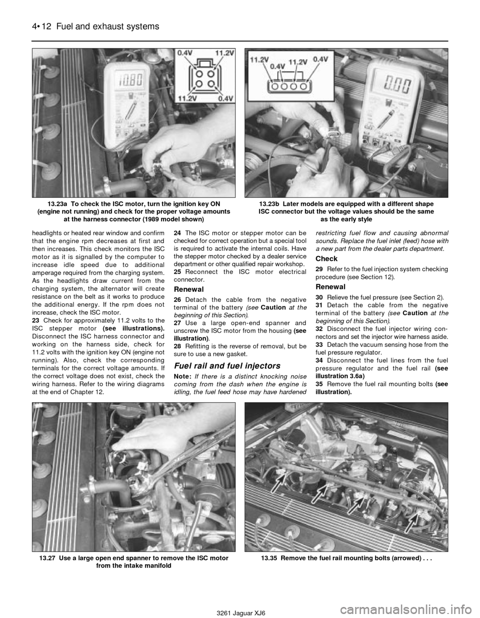
23Check for approximately 11.2 volts to the
ISC stepper motor (see illustrations).
Disconnect the ISC harness connector and
working on the harness side, check for
11.2 volts with the ignition key ON (engine not
running). Also, check the corresponding
terminals for the correct voltage amounts. If
the correct voltage does not exist, check the
wiring harness. Refer to the wiring diagrams
at the end of Chapter 12.24The ISC motor or stepper motor can be
checked for correct operation but a special tool
is required to activate the internal coils. Have
the stepper motor checked by a dealer service
department or other qualified repair workshop.
25Reconnect the ISC motor electrical
connector.
Renewal
26Detach the cable from the negative
terminal of the battery (see Cautionat the
beginning of this Section).
27Use a large open-end spanner and
unscrew the ISC motor from the housing (see
illustration).
28Refitting is the reverse of removal, but be
sure to use a new gasket.
Fuel rail and fuel injectors
Note:If there is a distinct knocking noise
coming from the dash when the engine is
idling, the fuel feed hose may have hardenedrestricting fuel flow and causing abnormal
sounds. Replace the fuel inlet (feed) hose with
a new part from the dealer parts department.
Check
29Refer to the fuel injection system checking
procedure (see Section 12).
Renewal
30Relieve the fuel pressure (see Section 2).
31Detach the cable from the negative
terminal of the battery (see Cautionat the
beginning of this Section).
32Disconnect the fuel injector wiring con-
nectors and set the injector wire harness aside.
33Detach the vacuum sensing hose from the
fuel pressure regulator.
34Disconnect the fuel lines from the fuel
pressure regulator and the fuel rail (see
illustration 3.6a)
35Remove the fuel rail mounting bolts (see
illustration).
4•12 Fuel and exhaust systems
3261 Jaguar XJ6 13.23a To check the ISC motor, turn the ignition key ON
(engine not running) and check for the proper voltage amounts
at the harness connector (1989 model shown)
13.23b Later models are equipped with a different shape
ISC connector but the voltage values should be the same
as the early style
13.27 Use a large open end spanner to remove the ISC motor
from the intake manifold13.35 Remove the fuel rail mounting bolts (arrowed) . . .
Page 101 of 227
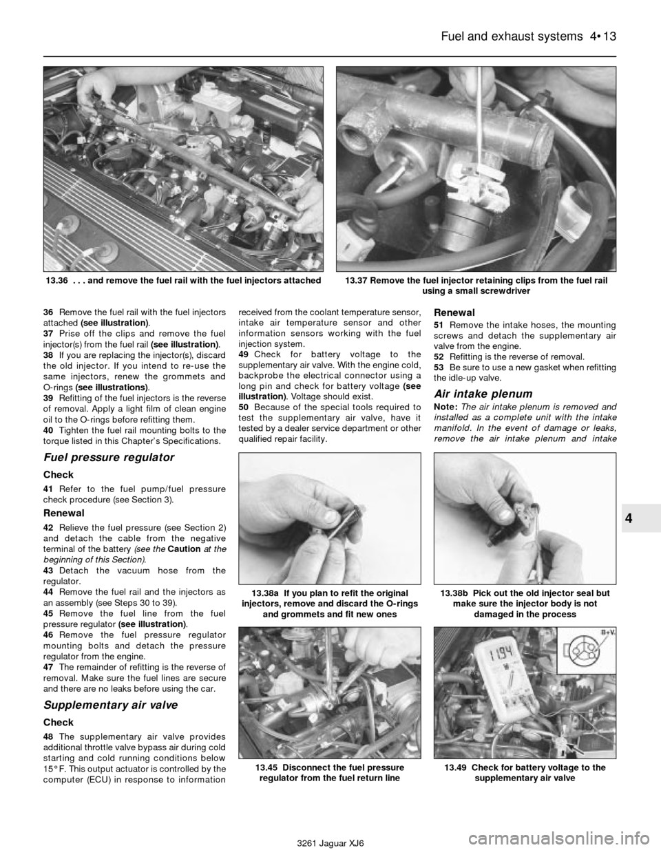
36Remove the fuel rail with the fuel injectors
attached (see illustration).
37Prise off the clips and remove the fuel
injector(s) from the fuel rail (see illustration).
38If you are replacing the injector(s), discard
the old injector. If you intend to re-use the
same injectors, renew the grommets and
O-rings (see illustrations).
39Refitting of the fuel injectors is the reverse
of removal. Apply a light film of clean engine
oil to the O-rings before refitting them.
40Tighten the fuel rail mounting bolts to the
torque listed in this Chapter’s Specifications.
Fuel pressure regulator
Check
41Refer to the fuel pump/fuel pressure
check procedure (see Section 3).
Renewal
42Relieve the fuel pressure (see Section 2)
and detach the cable from the negative
terminal of the battery (see the Cautionat the
beginning of this Section).
43Detach the vacuum hose from the
regulator.
44Remove the fuel rail and the injectors as
an assembly (see Steps 30 to 39).
45Remove the fuel line from the fuel
pressure regulator (see illustration).
46Remove the fuel pressure regulator
mounting bolts and detach the pressure
regulator from the engine.
47The remainder of refitting is the reverse of
removal. Make sure the fuel lines are secure
and there are no leaks before using the car.
Supplementary air valve
Check
48The supplementary air valve provides
additional throttle valve bypass air during cold
starting and cold running conditions below
15° F. This output actuator is controlled by the
computer (ECU) in response to informationreceived from the coolant temperature sensor,
intake air temperature sensor and other
information sensors working with the fuel
injection system.
49Check for battery voltage to the
supplementary air valve. With the engine cold,
backprobe the electrical connector using a
long pin and check for battery voltage (see
illustration). Voltage should exist.
50Because of the special tools required to
test the supplementary air valve, have it
tested by a dealer service department or other
qualified repair facility.
Renewal
51Remove the intake hoses, the mounting
screws and detach the supplementary air
valve from the engine.
52Refitting is the reverse of removal.
53Be sure to use a new gasket when refitting
the idle-up valve.
Air intake plenum
Note:The air intake plenum is removed and
installed as a complete unit with the intake
manifold. In the event of damage or leaks,
remove the air intake plenum and intake
Fuel and exhaust systems 4•13
4
3261 Jaguar XJ6 13.36 . . . and remove the fuel rail with the fuel injectors attached
13.37 Remove the fuel injector retaining clips from the fuel rail
using a small screwdriver
13.45 Disconnect the fuel pressure
regulator from the fuel return line
13.38b Pick out the old injector seal but
make sure the injector body is not
damaged in the process13.38a If you plan to refit the original
injectors, remove and discard the O-rings
and grommets and fit new ones
13.49 Check for battery voltage to the
supplementary air valve
Page 103 of 227
3261 Jaguar XJ6
5
Chapter 5
Engine electrical systems
Ignition system
Ignition timing (all models) . . . . . . . . . . . . . . . . . . . . . . . . . . . . . . . . . . . Not adjustable
Ignition coil resistance (at 68°F):
Primary resistance . . . . . . . . . . . . . . . . . . . . . . . . . . . . . . . . . . . . . . . 0.4 to 0.5 ohms
Secondary resistance . . . . . . . . . . . . . . . . . . . . . . . . . . . . . . . . . . . . . 6.0 to 6.5 k-ohms
Charging system
Charging voltage . . . . . . . . . . . . . . . . . . . . . . . . . . . . . . . . . . . . . . . . . . 13.9 to 15.1 volts
Standard amperage:
No load . . . . . . . . . . . . . . . . . . . . . . . . . . . . . . . . . . . . . . . . . . . . . . . . Less than 10 amps
Full load . . . . . . . . . . . . . . . . . . . . . . . . . . . . . . . . . . . . . . . . . . . . . . . 30 amps or more Amplifier - check and renewal . . . . . . . . . . . . . . . . . . . . . . . . . . . . . . 7
Alternator - removal and refitting . . . . . . . . . . . . . . . . . . . . . . . . . . . . 12
Battery cables - check and renewal . . . . . . . . . . . . . . . . . . . . . . . . . 4
Battery check, maintenance and charging . . . . . . . . . . . See Chapter 1
Battery - emergency jump starting . . . . . . . . . . . . . . . . . . . . . . . . . . 2
Battery - removal and refitting . . . . . . . . . . . . . . . . . . . . . . . . . . . . . . 3
Charging system - check . . . . . . . . . . . . . . . . . . . . . . . . . . . . . . . . . . 11
Charging system - general information and precautions . . . . . . . . . 10
CHECK ENGINE light . . . . . . . . . . . . . . . . . . . . . . . . . . . See Chapter 6
Distributor - removal and refitting . . . . . . . . . . . . . . . . . . . . . . . . . . . 9
Drivebelt check, adjustment and renewal . . . . . . . . . . . See Chapter 1General information . . . . . . . . . . . . . . . . . . . . . . . . . . . . . . . . . . . . . . 1
Ignition coil - check and renewal . . . . . . . . . . . . . . . . . . . . . . . . . . . . 8
Ignition system - check . . . . . . . . . . . . . . . . . . . . . . . . . . . . . . . . . . . 6
Ignition system - general information and precautions . . . . . . . . . . . 5
Spark plug renewal . . . . . . . . . . . . . . . . . . . . . . . . . . . . . See Chapter 1
Spark plug lead, distributor cap and rotor check
and renewal . . . . . . . . . . . . . . . . . . . . . . . . . . . . . . . . See Chapter 1
Starter motor - removal and refitting . . . . . . . . . . . . . . . . . . . . . . . . . 15
Starter motor - testing in vehicle . . . . . . . . . . . . . . . . . . . . . . . . . . . . 14
Starter solenoid - removal and refitting . . . . . . . . . . . . . . . . . . . . . . . 16
Starting system - general information and precautions . . . . . . . . . . 13
5•1
Specifications Contents
Easy,suitable for
novice with little
experienceFairly easy,suitable
for beginner with
some experienceFairly difficult,
suitable for competent
DIY mechanic
Difficult,suitable for
experienced DIY
mechanicVery difficult,
suitable for expert DIY
or professional
Degrees of difficulty
54321
1 General information
The engine electrical systems include all
ignition, charging and starting components.
Because of their engine related functions,
these components are discussed separately
from chassis electrical devices such as the
fuses, relays, lights, etc. (which are included in
Chapter 12).
Always observe the following precautions
when working on the electrical systems:
a) Be extremely careful when servicing
engine electrical components. They are
easily damaged if checked, connected or
handled improperly.
b) Never leave the ignition switch on for long
periods of time (10 minutes maximum)
with the engine off.c) Don’t disconnect the battery cables while
the engine is running.
d) Maintain correct polarity when connecting
a battery cable from another vehicle
during jump starting.
e) Always disconnect the negative cable first
and hook it up last or the battery may be
shorted by the tool being used to loosen
the cable clamps.
It’s also a good idea to review the safety-
related information regarding the engine
electrical systems in the Safety first section
near the front of this manual before beginning
any operation included in this Chapter.
2 Battery-
emergency jump starting
1
See “Jump starting”in “Roadside repairs”
at the front of this Manual.
3 Battery- removal and refitting
1
1Disconnect the negative terminal, then the
positive terminal from the battery. On 1989 to
1992 models, the battery is located in the
engine compartment on the passenger side
bulkhead and on 1993 and 1994 models, it is
located in the boot.
Caution: If the stereo in your vehicle is
equipped with an anti-theft system, make
sure you have the correct activation code
before disconnecting the battery.
2Remove the battery hold-down clamp.
3Lift out the battery. Be careful, it’s heavy.
4While the battery is out, inspect the carrier
(tray) for corrosion.
5If you are replacing the battery, make sure
that you get one that’s identical, with the
Page 104 of 227
same dimensions, amperage rating, cold
cranking rating, etc. as the original.
6Refitting is the reverse of removal.
4 Battery cables-
check and renewal
1
Caution: If the stereo in your vehicle is
equipped with an anti-theft system, make
sure you have the correct activation code
before disconnecting the battery.
1Periodically inspect the entire length of
each battery cable for damage, cracked or
burned insulation and corrosion. Poor battery
cable connections can cause starting
problems and decreased engine performance.
2Check the cable-to-terminal connections at
the ends of the cables for cracks, loose wire
strands and corrosion. The presence of white,
fluffy deposits under the insulation at the
cable terminal connection is a sign that the
cable is corroded and should be renewed.
Check the terminals for distortion, missing
mounting bolts and corrosion.
3When removing the cables, always
disconnect the negative cable first and hook it
up last or the battery may be shorted by the
tool used to loosen the cable clamps. Even if
only the positive cable is being renewed, be
sure to disconnect the negative cable from
the battery first (see Chapter 1 for further
information regarding battery cable removal).
4Disconnect the cables from the battery,
then trace each of them to their opposite ends
and detach them from the starter solenoid
and earth terminals. Note the routing of each
cable to ensure correct refitting.
5If you are replacing either or both of the old
cables, take them with you when buying new
items. It is vitally important that you replace
the cables with identical parts. Cables have
characteristics that make them easy to
identify: positive cables are usually red, larger
in cross-section and have a larger diameter
battery post clamp; earth cables are usually
black, smaller in cross-section and have a
slightly smaller diameter clamp for the
negative post.
6Clean the threads of the solenoid or earth
connection with a wire brush to remove rust
and corrosion. Apply a light coat of battery
terminal corrosion inhibitor, or petroleum jelly,
to the threads to prevent future corrosion.
7Attach the cable to the solenoid or earth
connection and tighten the mounting nut/bolt
securely.
8Before connecting a new cable to the
battery, make sure that it reaches the battery
post without having to be stretched.
9Connect the positive cable first, followed by
the negative cable.
5 Ignition system- general
information and precautions
1All models are equipped with a computerised
ignition system. The ignition system consists of
the ignition coil, the crankshaft position sensor,
the amplifier and the electronic control unit
(ECU). The ignition ECU controls the ignition
timing and advance characteristics for the
engine. The ignition timing is not adjustable,
therefore, changing the position of the distributor
will not change the timing in any way. Note:In
the event the distributor must be removed from
the engine, be sure to follow the precautions
described in Section 9 and mark the engine and
distributor with paint to ensure correct refitting. If
the distributor is not marked and Ihe crankshaft is
turned while the distributor is out of the engine,
have the distributor installed by a dealer service
department. The distributor must be installed
using a special alignment tool.
2The distributor is driven by the intermediate
shaft which also drives the power steering pump.
The crankshaft position sensor is located on the
front timing cover. It detects crank position by
pulsing an electronic signal to the ECU. This
signal is sent to the ECU to provide ignition
timing specifications.
3The computerised ignition system provides
complete control of the ignition timing by
determining the optimum timing in response to
engine speed, coolant temperature, throttle
position and vacuum pressure in the intake
manifold. These parameters are relayed to the
ECU by the crankshaft position sensor, throttle
potentiometer, coolant temperature sensor and
MAF sensor. Ignition timing is altered during
warm-up, idling and warm running conditions by
the ECU. This electronic ignition system also
consists of the ignition switch, battery, coil,
distributor, spark plug leads and spark plugs.
4Refer to a dealer parts department or car
accessory outlet for any questions concerning
the availability of the distributor parts and
assemblies. Testing the crankshaft position
sensor is covered in Chapter 6.
5When working on the ignition system, take
the following precautions:
a) Do not keep the ignition switch on for
more than 10 seconds if the engine will
not start.
b) Always connect a tachometer in
accordance with the manufacturer’s
instructions. Some tachometers may be
incompatible with this ignition system.
Consult a dealer service department
before buying a tachometer for use with
this vehicle.
c) Never allow the ignition coil terminals to
touch earth. Earthing the coil could result
in damage to the igniter and/or the
ignition coil.
d) Do not disconnect the battery when the
engine is running.
6 Ignition system- check
2
Warning: Because of the high
voltage generated by the
ignition system, extreme care
should be taken when working
on the ignition components. This not only
includes the amplifier, coil, distributor and
spark plug leads, but related components
such as connectors, tachometer and other
test equipment also.
1With the ignition switch turned to the “ON”
position, a “Battery” light or an “Oil Pressure”
light is a basic check for ignition and battery
supply to the ECU.
2Check all ignition wiring connections for
tightness, cuts, corrosion or any other signs of a
bad connection.
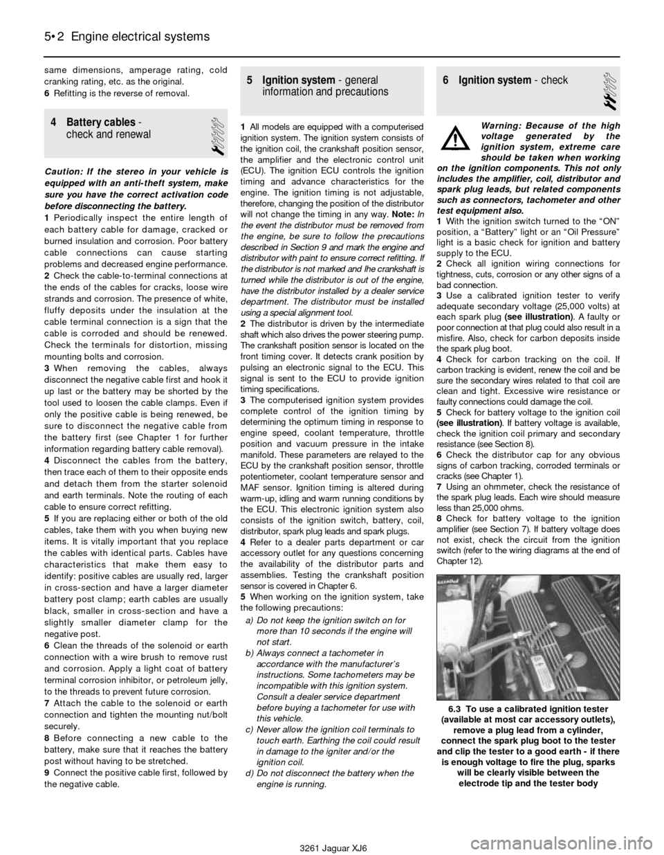
3Use a calibrated ignition tester to verify
adequate secondary voltage (25,000 volts) at
each spark plug (see illustration). A faulty or
poor connection at that plug could also result in a
misfire. Also, check for carbon deposits inside
the spark plug boot.
4Check for carbon tracking on the coil. If
carbon tracking is evident, renew the coil and be
sure the secondary wires related to that coil are
clean and tight. Excessive wire resistance or
faulty connections could damage the coil.
5Check for battery voltage to the ignition coil
(see illustration). If battery voltage is available,
check the ignition coil primary and secondary
resistance (see Section 8).
6Check the distributor cap for any obvious
signs of carbon tracking, corroded terminals or
cracks (see Chapter 1).
7Using an ohmmeter, check the resistance of
the spark plug leads. Each wire should measure
less than 25,000 ohms.
8Check for battery voltage to the ignition
amplifier (see Section 7). If battery voltage does
not exist, check the circuit from the ignition
switch (refer to the wiring diagrams at the end of
Chapter 12).
5•2 Engine electrical systems
6.3 To use a calibrated ignition tester
(available at most car accessory outlets),
remove a plug lead from a cylinder,
connect the spark plug boot to the tester
and clip the tester to a good earth - if there
is enough voltage to fire the plug, sparks
will be clearly visible between the
electrode tip and the tester body
3261 Jaguar XJ6
Page 105 of 227
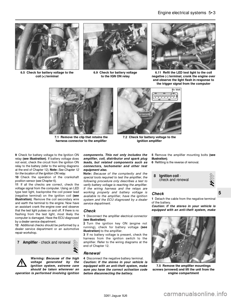
9Check for battery voltage to the Ignition ON
relay (see illustration). If battery voltage does
not exist, check the circuit from the ignition ON
relay to the battery (refer to the wiring diagrams
at the end of Chapter 12). Note:See Chapter 12
for the location of the Ignition ON relay.
10Check the operation of the crankshaft
position sensor (see Chapter 6).
11If all the checks are correct, check the
voltage signal from the computer. Using an LED
type test light, backprobe the coil power lead
(negative terminal) on the ignition coil (see
illustration). Remove the coil secondary wire
and earth the terminal to the engine. Now have
an assistant crank the engine over and observe
that the test light pulses on and off. If there is no
flashing from the test light, most likely the
computer is damaged. Have the ECU diagnosed
by a dealer service department.
12Additional checks should be performed by a
dealer service department or an automotive
repair workshop.
7 Amplifier- check and renewal
2
Warning: Because of the high
voltage generated by the
ignition system, extreme care
should be taken whenever an
operation is performed involving ignitioncomponents. This not only includes the
amplifier, coil, distributor and spark plug
leads, but related components such as
connectors, tachometer and other test
equipment also.
Note:Because of the complexity and the
special tools required to test the amplifier, the
following procedure only describes a test to
verify battery voltage is reaching the amplifier.
If the wiring harness and the relays are
working properly and battery voltage is
available to the amplifier, have the ignition
system and the ECU diagnosed by a dealer
service department.
Check
1Disconnect the amplifier electrical connector
(see illustration).
2Turn the ignition key ON (engine not
running), check for battery voltage (see
illustration) to the amplifier.
3If no battery voltage is present, check the
harness from the ignition switch to the
amplifier. Refer to the wiring diagrams at the
end of Chapter 12.
Renewal
4Disconnect the negative battery terminal.
Caution: If the stereo in your vehicle is
equipped with an anti-theft system, make
sure you have the correct activation code
before disconnecting the battery.5Remove the amplifier mounting bolts (see
illustration).
6Refitting is the reverse of removal.
8 Ignition coil-
check and renewal
2
Check
1Detach the cable from the negative terminal
of the battery.
Caution: If the stereo in your vehicle is
equipped with an anti-theft system, make
Engine electrical systems 5•3
5
6.5 Check for battery voltage to the
coil (+) terminal6.9 Check for battery voltage
to the IGN ON relay6.11 Refit the LED test light to the coil
negative (-) terminal, crank the engine over
and observe the light flash in response to
the trigger signal from the computer
7.1 Remove the clip that retains the
harness connector to the amplifier7.2 Check for battery voltage to the
ignition amplifier
7.5 Remove the amplifier mountings
screws (arrowed) and lift the unit from the
engine compartment
3261 Jaguar XJ6
Page 106 of 227

sure you have the correct activation code
before disconnecting the battery.
2Disconnect the electrical connectors and
the coil wire from the coil.
3Using an ohmmeter, check the coil
resistance:
a) Measure the resistance between the
positive and negative terminals (see
illustration). Compare your reading with
the specified coil primary resistance listed
in this Chapter’s Specifications.
b) Measure the resistance between the
positive terminal and the high tension (HT)
terminal(see illustration). Compare your
reading with the specified coil secondary
resistance listed in this Chapter’s
Specifications.
4If either of the above tests yield resistance
values outside the specified amount, renew
the coil.
Renewal
5Detach the battery negative cable.
Caution: If the stereo in your vehicle is
equipped with an anti-theft system, make
sure you have the correct activation code
before disconnecting the battery. 6Label and disconnect the electrical wires
from the coil terminals.
7Remove the coil mounting fasteners (see
illustration).
8Refitting is the reverse of removal.
9 Distributor-
removal and refitting
2
Note:The timing on this ignition system cannot
be adjusted by turning the distributor. Ignition
timing is maintained by the ECU at all times. In
the event the distributor must be removed from
the engine, be sure to follow the precautions
described in this section and mark the engine
and distributor with paint to ensure correct
refitting. If the distributor is not marked, and the
crankshaft is turned while the distributor is out of
the engine, have the distributor installed by a
dealer service department. The distributor must
be installed using a special alignment tool.
Removal
1Detach the battery negative cable. Caution: If the stereo in your vehicle is
equipped with an anti-theft system, make
sure you have the correct activation code
before disconnecting the battery.
2Disconnect the electrical connectors from
the distributor.
3Look for a raised “1” on the distributor cap.
This marks the location for the number one
cylinder spark plug lead terminal. If the cap
does not have a mark for the number one
terminal, locate the number one spark plug
and trace the wire back to the terminal on the
cap.
4Remove the distributor cap (see Chapter 1)
and rotate the engine until the rotor is pointing
toward the number one spark plug terminal.
5Make a mark on the edge of the distributor
base directly below the rotor tip and in line
with it. Also, mark the distributor base and the
engine block to ensure that the distributor is
installed correctly (see illustrations).
6Remove the distributor hold-down bolt,
then pull the distributor out to remove it.
Caution: DO NOT turn the crankshaft while
the distributor is out of the engine, or the
alignment marks will be useless.
5•4 Engine electrical systems
8.3a To check the primary resistance of
the coil, measure the resistance between
the positive and the negative terminals8.3b To check the secondary resistance of
the coil, measure the resistance between
the positive terminal and the HT terminal8.7 Remove the nuts from the coil
mounting bracket (arrowed)
3261 Jaguar XJ6
9.5a Paint or scribe a mark (arrowed) on the edge of the
distributor housing below the rotor tip to ensure that the rotor is
pointing in the same direction when the distributor is reinstalled9.5b Paint or scribe another mark across the cylinder head and
the distributor body (arrowed) to ensure that the distributor is
aligned correctly when it is reinstalled
Page 107 of 227
Refitting
7Insert the distributor into the engine in
exactly the same relationship to the block that
it was in when removed.
8If the distributor does not seat completely,
recheck the alignment marks between the
distributor base and the block to verify that
the distributor is in the same position it was in
before removal. Also check the rotor to see if
it’s aligned with the mark you made on the
edge of the distributor base.
9Refit the distributor hold-down bolt(s).
10The remainder of refitting is the reverse of
removal.
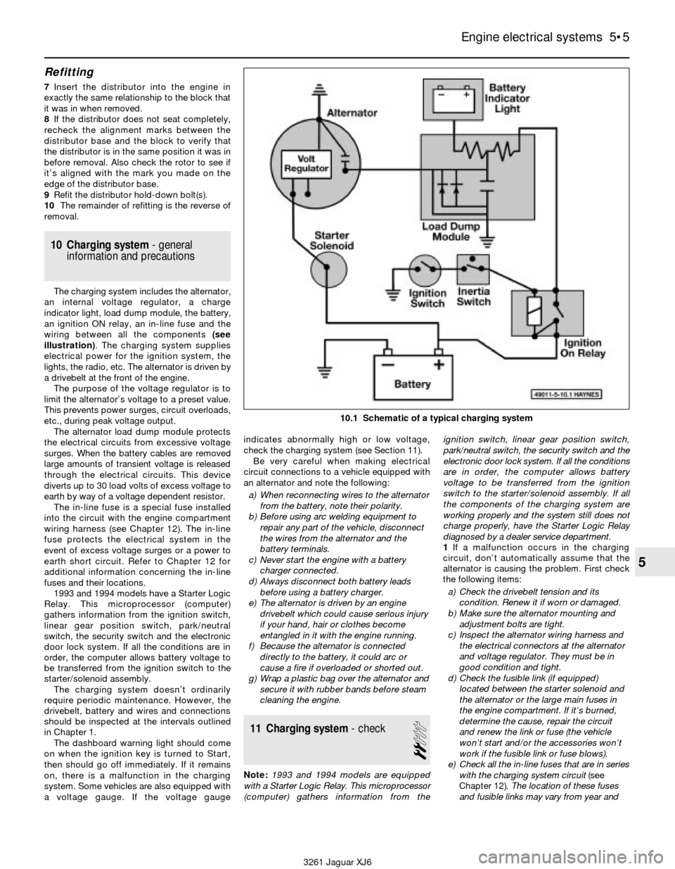
10 Charging system- general
information and precautions
The charging system includes the alternator,
an internal voltage regulator, a charge
indicator light, load dump module, the battery,
an ignition ON relay, an in-line fuse and the
wiring between all the components (see
illustration). The charging system supplies
electrical power for the ignition system, the
lights, the radio, etc. The alternator is driven by
a drivebelt at the front of the engine.
The purpose of the voltage regulator is to
limit the alternator’s voltage to a preset value.
This prevents power surges, circuit overloads,
etc., during peak voltage output.
The alternator load dump module protects
the electrical circuits from excessive voltage
surges. When the battery cables are removed
large amounts of transient voltage is released
through the electrical circuits. This device
diverts up to 30 load volts of excess voltage to
earth by way of a voltage dependent resistor.
The in-line fuse is a special fuse installed
into the circuit with the engine compartment
wiring harness (see Chapter 12). The in-line
fuse protects the electrical system in the
event of excess voltage surges or a power to
earth short circuit. Refer to Chapter 12 for
additional information concerning the in-line
fuses and their locations.
1993 and 1994 models have a Starter Logic
Relay. This microprocessor (computer)
gathers information from the ignition switch,
linear gear position switch, park/neutral
switch, the security switch and the electronic
door lock system. If all the conditions are in
order, the computer allows battery voltage to
be transferred from the ignition switch to the
starter/solenoid assembly.
The charging system doesn’t ordinarily
require periodic maintenance. However, the
drivebelt, battery and wires and connections
should be inspected at the intervals outlined
in Chapter 1.
The dashboard warning light should come
on when the ignition key is turned to Start,
then should go off immediately. If it remains
on, there is a malfunction in the charging
system. Some vehicles are also equipped with
a voltage gauge. If the voltage gaugeindicates abnormally high or low voltage,
check the charging system (see Section 11).
Be very careful when making electrical
circuit connections to a vehicle equipped with
an alternator and note the following:
a) When reconnecting wires to the alternator
from the battery, note their polarity.
b) Before using arc welding equipment to
repair any part of the vehicle, disconnect
the wires from the alternator and the
battery terminals.
c) Never start the engine with a battery
charger connected.
d) Always disconnect both battery leads
before using a battery charger.
e) The alternator is driven by an engine
drivebelt which could cause serious injury
if your hand, hair or clothes become
entangled in it with the engine running.
f) Because the alternator is connected
directly to the battery, it could arc or
cause a fire if overloaded or shorted out.
g) Wrap a plastic bag over the alternator and
secure it with rubber bands before steam
cleaning the engine.
11 Charging system- check
2
Note:1993 and 1994 models are equipped
with a Starter Logic Relay. This microprocessor
(computer) gathers information from theignition switch, linear gear position switch,
park/neutral switch, the security switch and the
electronic door lock system. If all the conditions
are in order, the computer allows battery
voltage to be transferred from the ignition
switch to the starter/solenoid assembly. If all
the components of the charging system are
working properly and the system still does not
charge properly, have the Starter Logic Relay
diagnosed by a dealer service department.
1If a malfunction occurs in the charging
circuit, don’t automatically assume that the
alternator is causing the problem. First check
the following items:
a) Check the drivebelt tension and its
condition. Renew it if worn or damaged.
b) Make sure the alternator mounting and
adjustment bolts are tight.
c) Inspect the alternator wiring harness and
the electrical connectors at the alternator
and voltage regulator. They must be in
good condition and tight.
d) Check the fusible link (if equipped)
located between the starter solenoid and
the alternator or the large main fuses in
the engine compartment. If it’s burned,
determine the cause, repair the circuit
and renew the link or fuse (the vehicle
won’t start and/or the accessories won’t
work if the fusible link or fuse blows).
e) Check all the in-line fuses that are in series
with the charging system circuit (see
Chapter 12).The location of these fuses
and fusible links may vary from year and
Engine electrical systems 5•5
5
10.1 Schematic of a typical charging system
3261 Jaguar XJ6
Page 108 of 227
model but the designations are the same.
Refer to the wiring diagrams at the end of
Chapter 12.
f) Start the engine and check the alternator
for abnormal noises (a shrieking or
squealing sound indicates a bad bushing).
g) Check the specific gravity of the battery
electrolyte. If it’s low, charge the battery
(doesn’t apply to maintenance free
batteries).
h) Make sure that the battery is fully charged
(one bad cell in a battery can cause
overcharging by the alternator).
i) Disconnect the battery cables (negative
first, then positive). Caution:If the stereo
in your vehicle is equipped with an anti-
theft system, make sure you have the
correct activation code before
disconnecting the battery. Inspect the
battery posts and the cable clamps for
corrosion. Clean them thoroughly if
necessary (see Chapter 1). Reconnect the
positive cable, then the negative cable.
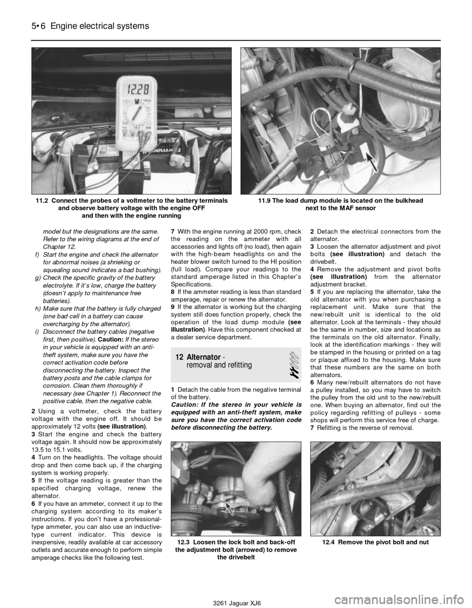
2Using a voltmeter, check the battery
voltage with the engine off. It should be
approximately 12 volts (see illustration).
3Start the engine and check the battery
voltage again. It should now be approximately
13.5 to 15.1 volts.
4Turn on the headlights. The voltage should
drop and then come back up, if the charging
system is working properly.
5If the voltage reading is greater than the
specified charging voltage, renew the
alternator.
6If you have an ammeter, connect it up to the
charging system according to its maker’s
instructions. If you don’t have a professional-
type ammeter, you can also use an inductive-
type current indicator. This device is
inexpensive, readily available at car accessory
outlets and accurate enough to perform simple
amperage checks like the following test.7With the engine running at 2000 rpm, check
the reading on the ammeter with all
accessories and lights off (no load), then again
with the high-beam headlights on and the
heater blower switch turned to the HI position
(full load). Compare your readings to the
standard amperage listed in this Chapter’s
Specifications.
8If the ammeter reading is less than standard
amperage, repair or renew the alternator.
9If the alternator is working but the charging
system still does function properly, check the
operation of the load dump module (see
illustration). Have this component checked at
a dealer service department.
12 Alternator-
removal and refitting
2
1Detach the cable from the negative terminal
of the battery.
Caution: If the stereo in your vehicle is
equipped with an anti-theft system, make
sure you have the correct activation code
before disconnecting the battery.2Detach the electrical connectors from the
alternator.
3Loosen the alternator adjustment and pivot
bolts (see illustration) and detach the
drivebelt.
4Remove the adjustment and pivot bolts
(see illustration)from the alternator
adjustment bracket.
5If you are replacing the alternator, take the
old alternator with you when purchasing a
replacement unit. Make sure that the
new/rebuilt unit is identical to the old
alternator. Look at the terminals - they should
be the same in number, size and locations as
the terminals on the old alternator. Finally,
look at the identification markings - they will
be stamped in the housing or printed on a tag
or plaque affixed to the housing. Make sure
that these numbers are the same on both
alternators.
6Many new/rebuilt alternators do not have
a pulley installed, so you may have to switch
the pulley from the old unit to the new/rebuilt
one. When buying an alternator, find out the
policy regarding refitting of pulleys - some
shops will perform this service free of charge.
7Refitting is the reverse of removal.
5•6 Engine electrical systems
12.3 Loosen the lock bolt and back-off
the adjustment bolt (arrowed) to remove
the drivebelt12.4 Remove the pivot bolt and nut
3261 Jaguar XJ6 11.2 Connect the probes of a voltmeter to the battery terminals
and observe battery voltage with the engine OFF
and then with the engine running
11.9 The load dump module is located on the bulkhead
next to the MAF sensor
Page 109 of 227
8After the alternator is installed, adjust the
drivebelt tension (see Chapter 1).
9Check the charging voltage to verify proper
operation of the alternator (see Section 11).
13 Starting system- general
information and precautions
The sole function of the starting system is
to crank the engine over quickly enough to
allow it to start.
The starting system consists of the battery,
the starter motor, the starter solenoid, the
starter relay and the electrical circuit
connecting the components. The solenoid is
mounted directly on the starter motor.
The solenoid/starter motor assembly is
installed on the upper part of the engine, next
to the transmission bellhousing.
When the ignition key is turned to the
START position, the starter solenoid is
actuated through the starter control circuit.
The starter solenoid then connects the battery
to the starter. The battery supplies the
electrical energy to the starter motor, which
does the actual work of cranking the engine.
The starter on a vehicle equipped with an
automatic transmission can be operated only
when the transmission selector lever is in Park
or Neutral.
These vehicles are equipped with either a
Bosch or Lucas starter assembly. The Lucas
unit is distinguished by the separate earth
strap from the solenoid to the starter body.
Bosch starter assemblies are equipped with a
solid metal earthing bar.
The starting system circuit is equipped with
a relay. The relay allows the ignition switch to
power the starter solenoid.
Always observe the following precautions
when working on the starting system:
a) Excessive cranking of the starter motor
can overheat it and cause serious
damage. Never operate the starter motor
for more than 15 seconds at a time
without pausing to allow it to cool for at
least two minutes.
b) The starter is connected directly to the
battery and could arc or cause a fire if
mishandled, overloaded or short circuited.
c) Always detach the cable from the
negative terminal of the battery before
working on the starting system.
Caution:If the stereo in your vehicle is
equipped with an anti-theft system, make
sure you have the correct activation code
before disconnecting the battery.
14 Starter motor-
testing in vehicle
2
1Make sure that the battery is charged and
that all cables, both at the battery and starter
solenoid terminals, are clean and secure.2If the starter motor does not turn at all when
the switch is operated, make sure that the
shift lever is in Neutral or Park (automatic
transmission) or that the clutch pedal is
depressed (manual transmission).
3If the starter motor spins but the engine is
not cranking, the overrunning clutch in the
starter motor is slipping and the starter motor
must be renewed.
4If, when the switch is actuated, the starter
motor does not operate at all but the solenoid
clicks, then the problem lies with either the
battery, the main solenoid contacts or the
starter motor itself (or the engine is seized).
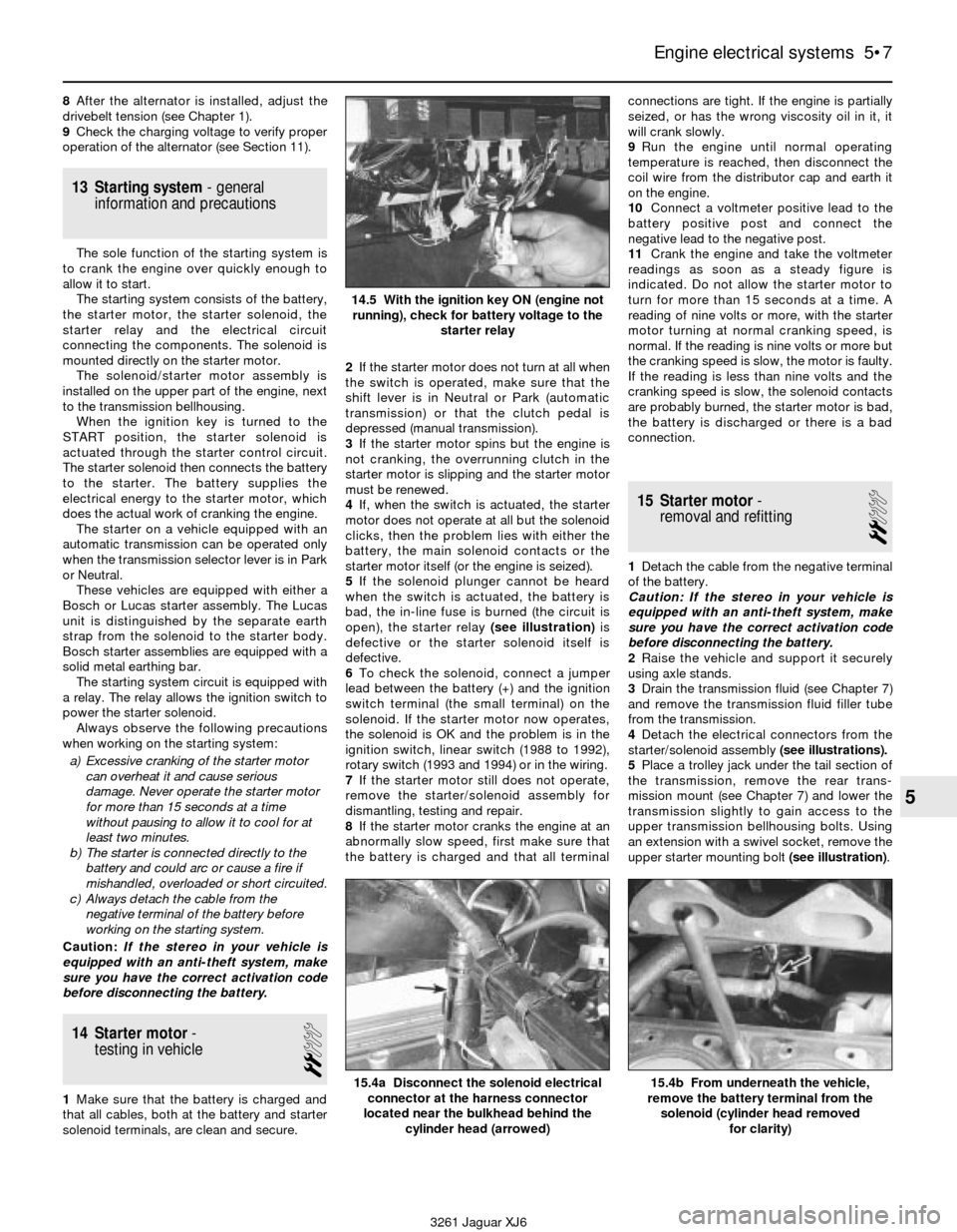
5If the solenoid plunger cannot be heard
when the switch is actuated, the battery is
bad, the in-line fuse is burned (the circuit is
open), the starter relay (see illustration)is
defective or the starter solenoid itself is
defective.
6To check the solenoid, connect a jumper
lead between the battery (+) and the ignition
switch terminal (the small terminal) on the
solenoid. If the starter motor now operates,
the solenoid is OK and the problem is in the
ignition switch, linear switch (1988 to 1992),
rotary switch (1993 and 1994) or in the wiring.
7If the starter motor still does not operate,
remove the starter/solenoid assembly for
dismantling, testing and repair.
8If the starter motor cranks the engine at an
abnormally slow speed, first make sure that
the battery is charged and that all terminalconnections are tight. If the engine is partially
seized, or has the wrong viscosity oil in it, it
will crank slowly.
9Run the engine until normal operating
temperature is reached, then disconnect the
coil wire from the distributor cap and earth it
on the engine.
10Connect a voltmeter positive lead to the
battery positive post and connect the
negative lead to the negative post.
11Crank the engine and take the voltmeter
readings as soon as a steady figure is
indicated. Do not allow the starter motor to
turn for more than 15 seconds at a time. A
reading of nine volts or more, with the starter
motor turning at normal cranking speed, is
normal. If the reading is nine volts or more but
the cranking speed is slow, the motor is faulty.
If the reading is less than nine volts and the
cranking speed is slow, the solenoid contacts
are probably burned, the starter motor is bad,
the battery is discharged or there is a bad
connection.
15 Starter motor-
removal and refitting
2
1Detach the cable from the negative terminal
of the battery.
Caution: If the stereo in your vehicle is
equipped with an anti-theft system, make
sure you have the correct activation code
before disconnecting the battery.
2Raise the vehicle and support it securely
using axle stands.
3Drain the transmission fluid (see Chapter 7)
and remove the transmission fluid filler tube
from the transmission.
4Detach the electrical connectors from the
starter/solenoid assembly (see illustrations).
5Place a trolley jack under the tail section of
the transmission, remove the rear trans-
mission mount (see Chapter 7) and lower the
transmission slightly to gain access to the
upper transmission bellhousing bolts. Using
an extension with a swivel socket, remove the
upper starter mounting bolt (see illustration).
Engine electrical systems 5•7
5
14.5 With the ignition key ON (engine not
running), check for battery voltage to the
starter relay
15.4a Disconnect the solenoid electrical
connector at the harness connector
located near the bulkhead behind the
cylinder head (arrowed)15.4b From underneath the vehicle,
remove the battery terminal from the
solenoid (cylinder head removed
for clarity)
3261 Jaguar XJ6
Page 110 of 227

6Working forward of the transmission, reach
up into the engine bellhousing area, under the
intake manifold and remove the lower starter
mounting bolt.
7Tilt the starter down and carefully lower the
starter assembly through the front, ahead of
the transmission.
8Refitting is the reverse of removal.16 Starter solenoid-
removal and refitting
2
1Remove the starter motor (see Section 15).
2Scribe or paint a mark across the starter
motor and solenoid assembly.3Disconnect the strap from the solenoid to
the starter motor terminal (if equipped).
4Remove the screws which secure the
solenoid to the starter drive end housing (see
illustration).
5Separate the solenoid from the starter.
6Refitting is the reverse of removal. Be sure
to align the paint or scribe mark.
5•8 Engine electrical systems
3261 Jaguar XJ6 15.5 The upper starter bolt can be reached from underneath the
vehicle using a long extension and swivel socket
(cylinder head removed for clarity)
16.4 Remove the three solenoid mounting screws (arrowed) and
separate the solenoid from the starter assembly