brake fluid JAGUAR XJ6 1997 2.G Owner's Manual
[x] Cancel search | Manufacturer: JAGUAR, Model Year: 1997, Model line: XJ6, Model: JAGUAR XJ6 1997 2.GPages: 227, PDF Size: 7.2 MB
Page 128 of 227
Refitting
8Place the disc on the hub and refit the disc
retaining screw. Tighten the screw securely.
9Refit the caliper mounting bracket, using a
new safety wire on the mounting bolts.
10Refit the brake pads and caliper (see
Section 3). Tighten all fasteners to the torque
listed in this Chapter’s Specifications.
11Refit the wheel and wheel nuts, then lower
the vehicle to the ground. Tighten the wheel
nuts to the specified torque (see Chapter 1
Specifications). Depress the brake pedal a
few times to bring the brake pads into contact
with the disc.
12Adjust the handbrake shoes, if necessary.
13Check the operation of the brakes
carefully, if possible before driving the vehicle
on public roads.
6 Master cylinder- removal,
overhaul and refitting
3
Note:Although master cylinder parts and
rebuild kits are available for most models, we
recommend replacing the master cylinder with
a new or remanufactured unit, if possible.
Removal
1The master cylinder is connected to the
brake servo, which is attached to the pedal
box, in front of the bulkhead on the driver’s
side of the engine compartment.
2Remove as much fluid as you can from the
reservoir with a syringe.
3Place rags under the line fittings and
prepare caps or plastic bags to cover the
ends of the lines once they are disconnected.
Caution: Brake fluid will damage paint.
Cover all body parts and be careful not to
spill fluid during this procedure.
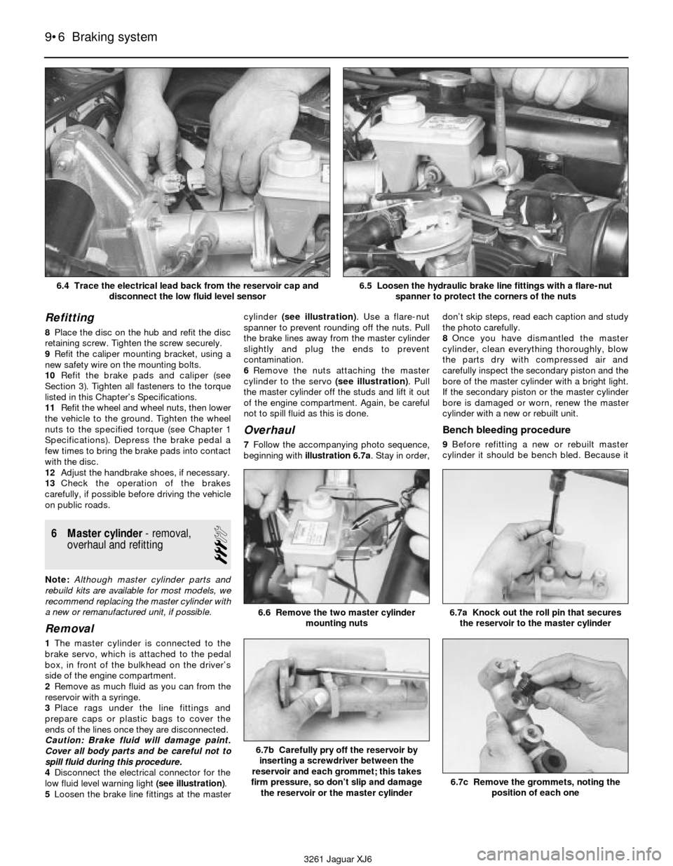
4Disconnect the electrical connector for the
low fluid level warning light (see illustration).
5Loosen the brake line fittings at the mastercylinder (see illustration). Use a flare-nut
spanner to prevent rounding off the nuts. Pull
the brake lines away from the master cylinder
slightly and plug the ends to prevent
contamination.
6Remove the nuts attaching the master
cylinder to the servo (see illustration). Pull
the master cylinder off the studs and lift it out
of the engine compartment. Again, be careful
not to spill fluid as this is done.
Overhaul
7Follow the accompanying photo sequence,
beginning with illustration 6.7a. Stay in order,don’t skip steps, read each caption and study
the photo carefully.
8Once you have dismantled the master
cylinder, clean everything thoroughly, blow
the parts dry with compressed air and
carefully inspect the secondary piston and the
bore of the master cylinder with a bright light.
If the secondary piston or the master cylinder
bore is damaged or worn, renew the master
cylinder with a new or rebuilt unit.
Bench bleeding procedure
9Before refitting a new or rebuilt master
cylinder it should be bench bled. Because it
9•6 Braking system
6.7a Knock out the roll pin that secures
the reservoir to the master cylinder
6.7b Carefully pry off the reservoir by
inserting a screwdriver between the
reservoir and each grommet; this takes
firm pressure, so don’t slip and damage
the reservoir or the master cylinder
6.7c Remove the grommets, noting the
position of each one
6.6 Remove the two master cylinder
mounting nuts
3261 Jaguar XJ6 6.4 Trace the electrical lead back from the reservoir cap and
disconnect the low fluid level sensor
6.5 Loosen the hydraulic brake line fittings with a flare-nut
spanner to protect the corners of the nuts
Page 129 of 227

Braking system 9•7
9
6.7d Pry off the end cap6.7e Locate the stopper pin (arrowed)
inside the forward grommet hole . . .6.7f . . . insert a punch into the pocket of
the primary piston, place the master
cylinder vertically as shown, push down
on the master cylinder to depress the
pistons and pull out the stopper pin
with a magnet
6.7g Remove the primary piston6.7h Remove the secondary piston6.7i If the secondary piston is stuck, rap
the master cylinder on a wood block to
dislodge it
3261 Jaguar XJ6
6.7j Remove the seals and cups from the
pistons - be very careful not to scratch the
piston surface - then wash the secondary
piston with clean brake fluid and inspect it;
if the secondary piston is damaged, you
must renew the master cylinder with a new
or rebuilt unit (a new primary piston is
included with the rebuild kit)6.7l The master cylinder assembly
1 Roll pin
2 Reservoir
3 Grommets
4 End plate
5 Primary piston
6 Secondary piston stopper pin
7 Secondary piston6.7k Refit the new O-ring seals and cups
as shown; make sure the cups on the
primary piston (the one on the left) face
forward as shown (toward the spring), and
the cups on the secondary piston (the one
on the right) face out, away from the piston
(the one on the left faces toward the
primary piston, the one on the right faces
toward the spring)
Page 130 of 227

will be necessary to apply pressure to the
master cylinder piston and, at the same time,
control flow from the brake line outlets, it is
recommended that the master cylinder be
mounted in a vice. Use caution not to clamp
the vice too tightly, or the master cylinder
body might crack.
10Insert threaded plugs into the brake line
outlet holes and snug them down so that
there will be no air leakage past them, but not
so tight that they cannot be easily loosened.
11Fill the reservoir with brake fluid of the
recommended type (see Recommended
lubricants and fluidsin Chapter 1).
12Remove one plug and push the piston
assembly into the master cylinder bore to
expel the air from the master cylinder. A large
Phillips screwdriver can be used to push on
the piston assembly.
13To prevent air from being drawn back into
the master cylinder, the plug must be
replaced and tightened before releasing the
pressure on the piston assembly.
14Repeat the procedure until only brake
fluid is expelled from the brake line outlet
hole. When only brake fluid is expelled, repeat
the procedure with the other outlet hole and
plug. Be sure to keep the master cylinder
reservoir filled with brake fluid to prevent the
introduction of air into the system.
15Since high pressure is not involved in the
bench bleeding procedure, an alternative to
the removal and renewal of the plugs witheach stroke of the piston assembly is
available. Before pushing in on the piston
assembly, remove the plug as described inStep 12. Before releasing the piston, however,
instead of replacing the plug, simply put your
finger tightly over the hole to keep air from
9•8 Braking system
6.7m Apply some clean brake fluid to the
secondary piston and refit it with the slot
oriented with the stopper pin hole, so that
the stopper pin will go through the slot6.7n Apply a coat of clean brake fluid to
the primary piston and refit it into the bore6.7o Using the same technique as in
illustration 6.7f, depress the pistons and
refit the stopper pin
6.7p Refit the end plate as shown, with the
bend in the plate flange aligned with the
groove in the master cylinder flange6.7q Using a hammer and punch, stake
the end plate as shown (there’s a dimple in
the side of the plate for this purpose)6.7r Refit the grommets
3261 Jaguar XJ6
6.7s Align the reservoir pipes with the
grommets as shown . . .
6.7u Refit the reservoir roll pin . . .6.7v . . . and tap it into place
6.7t . . . and squeeze the reservoir and
master cylinder together; make sure the
reservoir is fully seated
Page 131 of 227
being drawn back into the master cylinder.
Wait several seconds for brake fluid to be
drawn from the reservoir into the piston bore,
then depress the piston again, removing your
finger as brake fluid is expelled. Be sure to put
your finger back over the hole each time
before releasing the piston, and when the
bleeding procedure is complete for that outlet,
renew the plug and snug it up before going on
to the other port.
Refitting
16Refit the master cylinder over the studs on
the brake servo and tighten the mounting nuts
only finger tight at this time.
17Thread the brake line fittings into the
master cylinder. Since the master cylinder is
still a bit loose, it can be moved slightly to
allow the fitting threads to start easily. Do not
strip the threads as the fittings are tightened.
18Tighten the brake fittings securely and the
mounting nuts to the torque listed in this
Chapter’s Specifications.
19Fill the master cylinder reservoir with fluid,
then bleed the master cylinder and the brake
system (see Section 9).
20To bleed the master cylinder on the
vehicle, have an assistant pump the brake
pedal several times and then hold the pedal to
the floor. Loosen the fitting nut to allow air and
fluid to escape, then tighten the nut. Repeat
this procedure on both fittings until the fluid is
clear of air bubbles. Test the operation of the
brake system carefully before placing the
vehicle into service.
7 Brake servo-
general information,
removal and refitting
2
General information
1A hydraulic brake servo system assists
braking when the brake pedal is depressed.
The booster unit, located between the brake
pedal box and the master cylinder, is operated
by hydraulic pressure generated by an engine-
driven pump (on early models) or by an electric
pump (on later models). When the engine isrunning, the pump supplies hydraulic pressure
to an accumulator. The accumulator stores and
regulates the pressure to the hydraulic brake
servo. When you depress the brake pedal, the
pressure in the booster helps actuate the
master cylinder, reducing pedal effort.
2The hydraulic brake servo isn’t rebuildable;
if it fails, it must be replaced. Basic operation
can be checked (see Chapter 1, Section 15),
but in-depth testing of the system requires
special tools, so diagnosis is beyond the
scope of the home mechanic. If the system
fails, take it to a dealer service department or
other qualified repair workshop for repairs.
However, if the unit must be replaced, you
can do it yourself as follows.
Removal and refitting
3With the engine off, discharge the hydraulic
accumulator by depressing the brake pedal
several times until it feels hard to depress.
4Remove the master cylinder (see Section 6).
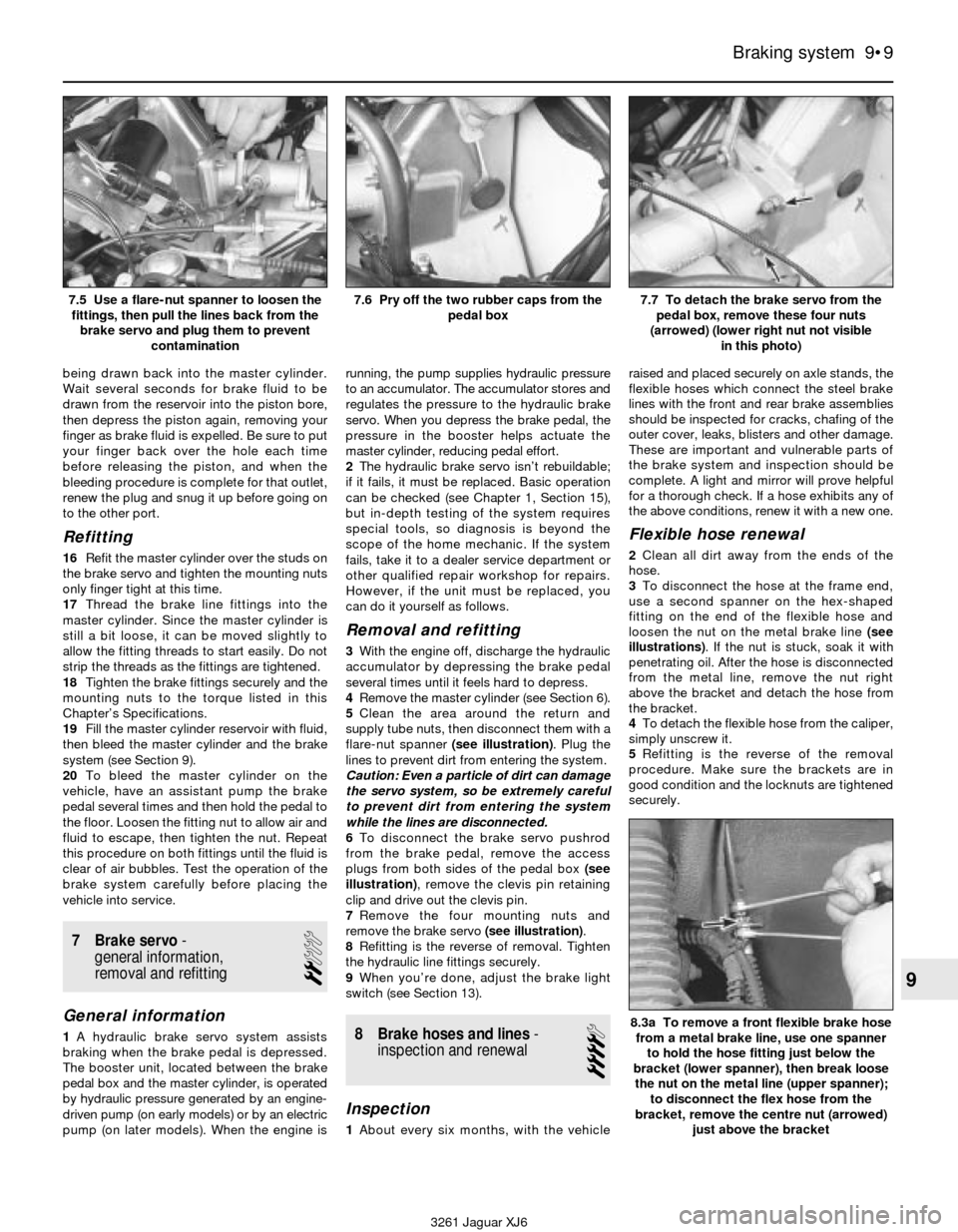
5Clean the area around the return and
supply tube nuts, then disconnect them with a
flare-nut spanner (see illustration). Plug the
lines to prevent dirt from entering the system.
Caution: Even a particle of dirt can damage
the servo system, so be extremely careful
to prevent dirt from entering the system
while the lines are disconnected.
6To disconnect the brake servo pushrod
from the brake pedal, remove the access
plugs from both sides of the pedal box (see
illustration), remove the clevis pin retaining
clip and drive out the clevis pin.
7Remove the four mounting nuts and
remove the brake servo (see illustration).
8Refitting is the reverse of removal. Tighten
the hydraulic line fittings securely.
9When you’re done, adjust the brake light
switch (see Section 13).
8 Brake hoses and lines-
inspection and renewal
4
Inspection
1About every six months, with the vehicleraised and placed securely on axle stands, the
flexible hoses which connect the steel brake
lines with the front and rear brake assemblies
should be inspected for cracks, chafing of the
outer cover, leaks, blisters and other damage.
These are important and vulnerable parts of
the brake system and inspection should be
complete. A light and mirror will prove helpful
for a thorough check. If a hose exhibits any of
the above conditions, renew it with a new one.
Flexible hose renewal
2Clean all dirt away from the ends of the
hose.
3To disconnect the hose at the frame end,
use a second spanner on the hex-shaped
fitting on the end of the flexible hose and
loosen the nut on the metal brake line (see
illustrations). If the nut is stuck, soak it with
penetrating oil. After the hose is disconnected
from the metal line, remove the nut right
above the bracket and detach the hose from
the bracket.
4To detach the flexible hose from the caliper,
simply unscrew it.
5Refitting is the reverse of the removal
procedure. Make sure the brackets are in
good condition and the locknuts are tightened
securely.
Braking system 9•9
9
7.5 Use a flare-nut spanner to loosen the
fittings, then pull the lines back from the
brake servo and plug them to prevent
contamination7.6 Pry off the two rubber caps from the
pedal box7.7 To detach the brake servo from the
pedal box, remove these four nuts
(arrowed) (lower right nut not visible
in this photo)
8.3a To remove a front flexible brake hose
from a metal brake line, use one spanner
to hold the hose fitting just below the
bracket (lower spanner), then break loose
the nut on the metal line (upper spanner);
to disconnect the flex hose from the
bracket, remove the centre nut (arrowed)
just above the bracket
3261 Jaguar XJ6
Page 132 of 227
6Carefully check to make sure the
suspension and steering components do not
make contact with the hoses. Have an
assistant push on the vehicle and also turn the
steering wheel from lock-to-lock during
inspection.
7Bleed the brake system (see Section 9).
Metal brake line renewal
8When replacing brake lines, use the proper
parts only. Do not use copper line for any
brake system connections. Purchase steel
brake lines from a dealer or motor factors..
9Unless you’re using factory renewal brake
lines, you may need a tubing bender to bend
the lines to the proper shape.
10First, remove the line you intend to renew,
lay it on a clean workbench and measure it
carefully. Obtain a new line of the same length
and bend it to match the pattern of the old
line.
Warning: Do not crimp or
damage the line. No bend should
have a smaller radius than
9/16-inch. Make sure the
protective coating on the new line is
undamaged at the bends.
11When refitting the new line, make sure it’s
well supported by the brackets, the routing
matches the original and there’s plenty of
clearance between moving or hot
components.
12After refitting, check the master cylinder
fluid level and add fluid as necessary. Bleed
the brake system as outlined in Section 9 and
test the brakes carefully before driving the
vehicle. Be sure there are no leaks.
9 Brake hydraulic system-
bleeding
2
Warning: Wear eye protection
when bleeding the brake
system. If the fluid comes in
contact with your eyes,
immediately rinse them with water and
seek medical attention.Note:Bleeding the hydraulic system is
necessary to remove any air which has entered
the system during removal and refitting of a
hose, line, caliper or master cylinder.
1It will probably be necessary to bleed the
system at all four brakes if air has entered the
system due to low fluid level or if the brake
lines have been disconnected at the master
cylinder.
2If a brake line was disconnected at only one
wheel, then only that caliper or wheel cylinder
must be bled.
3If a brake line is disconnected at a fitting
located between the master cylinder and any
of the brakes, that part of the system served
by the disconnected line must be bled.
4Bleed the right rear, the left rear, the right
front and the left front caliper, in that order,
when the entire system is involved.
5Remove any residual vacuum from the
servo and pressure in the anti-lock braking
system (if equipped) by applying the brake
about 30 times with the engine off.
6Remove the master cylinder reservoir cover
and fill the reservoir with brake fluid. Refit the
cover. Note:Check the fluid level often during
the bleeding operation and add fluid as
necessary to prevent the fluid level from falling
low enough to allow air into the master
cylinder.
7Have an assistant on hand, as well as a
supply of new brake fluid, an empty clear
plastic container, a length of 3/16-inch clear
tubing to fit over the bleed screws and a
spanner to open and close the bleed screws.
8Beginning at the right rear wheel, loosen the
bleed screw slightly, then tighten it to a point
where it is snug but can still be loosened
quickly and easily.
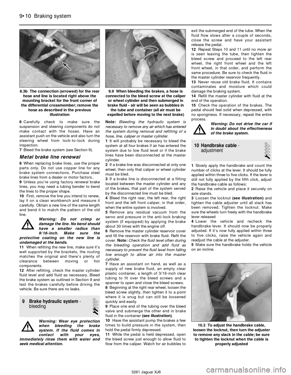
9Place one end of the tubing over the bleed
valve and submerge the other end in brake
fluid in the container (see illustration).
10Have the assistant pump the brakes a few
times to build pressure in the system, then
hold the pedal firmly depressed.
11While the pedal is held depressed, open
the bleed screw just enough to allow fluid to
flow from the caliper. Watch for air bubbles toexit the submerged end of the tube. When the
fluid flow slows after a couple of seconds,
close the screw and have your assistant
release the pedal.
12Repeat Steps 10 and 11 until no more air
is seen leaving the tube, then tighten the
bleed screw and proceed to the left rear
wheel, the right front wheel and the left
front wheel, in that order, and perform the
same procedure. Be sure to check the fluid in
the master cylinder reservoir frequently.
13Never reuse old brake fluid. It contains
contaminates and moisture which could
damage the braking system.
14Refill the master cylinder with fluid at the
end of the operation.
15Check the operation of the brakes. The
pedal should feel solid when depressed, with
no sponginess. If necessary, repeat the entire
process.
Warning: Do not drive the car if
in doubt about the effectiveness
of the brake system.
10 Handbrake cable-
adjustment
1
1Slowly apply the handbrake and count the
number of clicks at the lever. It should be fully
applied within three to five clicks. If the lever is
still not fully applied by the fifth click, adjust
the handbrake cable as follows:
2Raise the vehicle and place it securely on
axle stands.
3Loosen the locknut (see illustration)and
tighten the cable adjuster until all slack has
been removed. Tighten the locknut. Make
sure the wheels turn freely with the handbrake
lever released
4Lower the vehicle and recheck the
handbrake lever. It should now be properly
adjusted. If it’s now fully applied within three
to five clicks, raise the vehicle again and
readjust the cable at the adjuster.
5Make sure the handbrake holds the vehicle
on an incline.
9•10 Braking system
8.3b The connection (arrowed) for the rear
hose and line is located right above the
mounting bracket for the front corner of
the differential crossmember; remove the
hose as described in the previous
illustration9.9 When bleeding the brakes, a hose is
connected to the bleed screw at the caliper
or wheel cylinder and then submerged in
brake fluid - air will be seen as bubbles in
the tube and container (all air must be
expelled before moving to the next brake)
10.3 To adjust the handbrake cable,
loosen the locknut, then turn the adjuster
to remove any slack in the cable; be sure
to tighten the locknut when the cable is
properly adjusted
3261 Jaguar XJ6
Page 142 of 227
and support it securely on axle stands.
Remove the wheel.
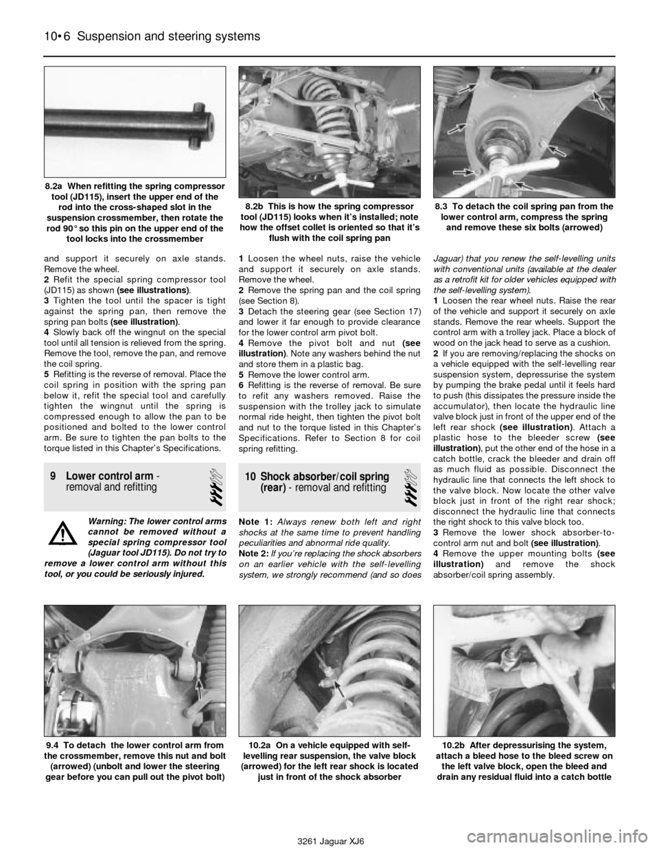
2Refit the special spring compressor tool
(JD115) as shown (see illustrations).
3Tighten the tool until the spacer is tight
against the spring pan, then remove the
spring pan bolts (see illustration).
4Slowly back off the wingnut on the special
tool until all tension is relieved from the spring.
Remove the tool, remove the pan, and remove
the coil spring.
5Refitting is the reverse of removal. Place the
coil spring in position with the spring pan
below it, refit the special tool and carefully
tighten the wingnut until the spring is
compressed enough to allow the pan to be
positioned and bolted to the lower control
arm. Be sure to tighten the pan bolts to the
torque listed in this Chapter’s Specifications.
9 Lower control arm-
removal and refitting
3
Warning: The lower control arms
cannot be removed without a
special spring compressor tool
(Jaguar tool JD115). Do not try to
remove a lower control arm without this
tool, or you could be seriously injured.1Loosen the wheel nuts, raise the vehicle
and support it securely on axle stands.
Remove the wheel.
2Remove the spring pan and the coil spring
(see Section 8).
3Detach the steering gear (see Section 17)
and lower it far enough to provide clearance
for the lower control arm pivot bolt.
4Remove the pivot bolt and nut (see
illustration). Note any washers behind the nut
and store them in a plastic bag.
5Remove the lower control arm.
6Refitting is the reverse of removal. Be sure
to refit any washers removed. Raise the
suspension with the trolley jack to simulate
normal ride height, then tighten the pivot bolt
and nut to the torque listed in this Chapter’s
Specifications. Refer to Section 8 for coil
spring refitting.
10 Shock absorber/coil spring
(rear)- removal and refitting
3
Note 1: Always renew both left and right
shocks at the same time to prevent handling
peculiarities and abnormal ride quality.
Note 2:If you’re replacing the shock absorbers
on an earlier vehicle with the self-levelling
system, we strongly recommend (and so doesJaguar) that you renew the self-levelling units
with conventional units (available at the dealer
as a retrofit kit for older vehicles equipped with
the self-levelling system).
1Loosen the rear wheel nuts. Raise the rear
of the vehicle and support it securely on axle
stands. Remove the rear wheels. Support the
control arm with a trolley jack. Place a block of
wood on the jack head to serve as a cushion.
2If you are removing/replacing the shocks on
a vehicle equipped with the self-levelling rear
suspension system, depressurise the system
by pumping the brake pedal until it feels hard
to push (this dissipates the pressure inside the
accumulator), then locate the hydraulic line
valve block just in front of the upper end of the
left rear shock (see illustration). Attach a
plastic hose to the bleeder screw (see
illustration), put the other end of the hose in a
catch bottle, crack the bleeder and drain off
as much fluid as possible. Disconnect the
hydraulic line that connects the left shock to
the valve block. Now locate the other valve
block just in front of the right rear shock;
disconnect the hydraulic line that connects
the right shock to this valve block too.
3Remove the lower shock absorber-to-
control arm nut and bolt (see illustration).
4Remove the upper mounting bolts (see
illustration)and remove the shock
absorber/coil spring assembly.
10•6 Suspension and steering systems
9.4 To detach the lower control arm from
the crossmember, remove this nut and bolt
(arrowed) (unbolt and lower the steering
gear before you can pull out the pivot bolt)10.2a On a vehicle equipped with self-
levelling rear suspension, the valve block
(arrowed) for the left rear shock is located
just in front of the shock absorber10.2b After depressurising the system,
attach a bleed hose to the bleed screw on
the left valve block, open the bleed and
drain any residual fluid into a catch bottle
3261 Jaguar XJ6 8.2a When refitting the spring compressor
tool (JD115), insert the upper end of the
rod into the cross-shaped slot in the
suspension crossmember, then rotate the
rod 90° so this pin on the upper end of the
tool locks into the crossmember
8.2b This is how the spring compressor
tool (JD115) looks when it’s installed; note
how the offset collet is oriented so that it’s
flush with the coil spring pan8.3 To detach the coil spring pan from the
lower control arm, compress the spring
and remove these six bolts (arrowed)
Page 206 of 227

3261 Jaguar XJ6
General repair proceduresREF•5
Whenever servicing, repair or overhaul work
is carried out on the car or its components, it
is necessary to observe the following
procedures and instructions. This will assist in
carrying out the operation efficiently and to a
professional standard of workmanship.
Joint mating faces and gaskets
When separating components at their
mating faces, never insert screwdrivers or
similar implements into the joint between the
faces in order to prise them apart. This can
cause severe damage which results in oil
leaks, coolant leaks, etc upon reassembly.
Separation is usually achieved by tapping
along the joint with a soft-faced hammer in
order to break the seal. However, note that
this method may not be suitable where
dowels are used for component location.
Where a gasket is used between the mating
faces of two components, ensure that it is
renewed on reassembly, and fit it dry unless
otherwise stated in the repair procedure. Make
sure that the mating faces are clean and dry,
with all traces of old gasket removed. When
cleaning a joint face, use a tool which is not
likely to score or damage the face, and remove
any burrs or nicks with an oilstone or fine file.
Make sure that tapped holes are cleaned
with a pipe cleaner, and keep them free of
jointing compound, if this is being used,
unless specifically instructed otherwise.
Ensure that all orifices, channels or pipes
are clear, and blow through them, preferably
using compressed air.
Oil seals
Oil seals can be removed by levering them
out with a wide flat-bladed screwdriver or
similar tool. Alternatively, a number of self-
tapping screws may be screwed into the seal,
and these used as a purchase for pliers or
similar in order to pull the seal free.
Whenever an oil seal is removed from its
working location, either individually or as part
of an assembly, it should be renewed.
The very fine sealing lip of the seal is easily
damaged, and will not seal if the surface it
contacts is not completely clean and free from
scratches, nicks or grooves. If the original
sealing surface of the component cannot be
restored, and the manufacturer has not made
provision for slight relocation of the seal
relative to the sealing surface, the component
should be renewed.
Protect the lips of the seal from any surface
which may damage them in the course of
fitting. Use tape or a conical sleeve where
possible. Lubricate the seal lips with oil before
fitting and, on dual-lipped seals, fill the space
between the lips with grease.
Unless otherwise stated, oil seals must be
fitted with their sealing lips toward the
lubricant to be sealed.
Use a tubular drift or block of wood of the
appropriate size to install the seal and, if the
seal housing is shouldered, drive the seal
down to the shoulder. If the seal housing isunshouldered, the seal should be fitted with
its face flush with the housing top face (unless
otherwise instructed).
Screw threads and fastenings
Seized nuts, bolts and screws are quite a
common occurrence where corrosion has set
in, and the use of penetrating oil or releasing
fluid will often overcome this problem if the
offending item is soaked for a while before
attempting to release it. The use of an impact
driver may also provide a means of releasing
such stubborn fastening devices, when used
in conjunction with the appropriate
screwdriver bit or socket. If none of these
methods works, it may be necessary to resort
to the careful application of heat, or the use of
a hacksaw or nut splitter device.
Studs are usually removed by locking two
nuts together on the threaded part, and then
using a spanner on the lower nut to unscrew
the stud. Studs or bolts which have broken off
below the surface of the component in which
they are mounted can sometimes be removed
using a stud extractor. Always ensure that a
blind tapped hole is completely free from oil,
grease, water or other fluid before installing
the bolt or stud. Failure to do this could cause
the housing to crack due to the hydraulic
action of the bolt or stud as it is screwed in.
When tightening a castellated nut to accept
a split pin, tighten the nut to the specified
torque, where applicable, and then tighten
further to the next split pin hole. Never
slacken the nut to align the split pin hole,
unless stated in the repair procedure.
When checking or retightening a nut or bolt
to a specified torque setting, slacken the nut
or bolt by a quarter of a turn, and then
retighten to the specified setting. However,
this should not be attempted where angular
tightening has been used.
For some screw fastenings, notably
cylinder head bolts or nuts, torque wrench
settings are no longer specified for the latter
stages of tightening, “angle-tightening” being
called up instead. Typically, a fairly low torque
wrench setting will be applied to the
bolts/nuts in the correct sequence, followed
by one or more stages of tightening through
specified angles.
Locknuts, locktabs and washers
Any fastening which will rotate against a
component or housing during tightening
should always have a washer between it and
the relevant component or housing.
Spring or split washers should always be
renewed when they are used to lock a critical
component such as a big-end bearing
retaining bolt or nut. Locktabs which are
folded over to retain a nut or bolt should
always be renewed.
Self-locking nuts can be re-used in non-
critical areas, providing resistance can be felt
when the locking portion passes over the bolt
or stud thread. However, it should be noted
that self-locking stiffnuts tend to lose theireffectiveness after long periods of use, and
should be renewed as a matter of course.
Split pins must always be replaced with
new ones of the correct size for the hole.
When thread-locking compound is found
on the threads of a fastener which is to be re-
used, it should be cleaned off with a wire
brush and solvent, and fresh compound
applied on reassembly.
Special tools
Some repair procedures in this manual
entail the use of special tools such as a press,
two or three-legged pullers, spring
compressors, etc. Wherever possible, suitable
readily-available alternatives to the
manufacturer’s special tools are described,
and are shown in use. In some instances,
where no alternative is possible, it has been
necessary to resort to the use of a
manufacturer’s tool, and this has been done
for reasons of safety as well as the efficient
completion of the repair operation. Unless you
are highly-skilled and have a thorough
understanding of the procedures described,
never attempt to bypass the use of any
special tool when the procedure described
specifies its use. Not only is there a very great
risk of personal injury, but expensive damage
could be caused to the components involved.
Environmental considerations
When disposing of used engine oil, brake
fluid, antifreeze, etc, give due consideration to
any detrimental environmental effects. Do not,
for instance, pour any of the above liquids
down drains into the general sewage system,
or onto the ground to soak away. Many local
council refuse tips provide a facility for waste
oil disposal, as do some garages. If none of
these facilities are available, consult your local
Environmental Health Department, or the
National Rivers Authority, for further advice.
With the universal tightening-up of
legislation regarding the emission of
environmentally-harmful substances from
motor vehicles, most current vehicles have
tamperproof devices fitted to the main
adjustment points of the fuel system. These
devices are primarily designed to prevent
unqualified persons from adjusting the fuel/air
mixture, with the chance of a consequent
increase in toxic emissions. If such devices
are encountered during servicing or overhaul,
they should, wherever possible, be renewed
or refitted in accordance with the vehicle
manufacturer’s requirements or current
legislation.
Note: It is
antisocial and
illegal to dump oil
down the drain.
To find the
location of your
local oil recycling
bank, call this
number free.
Page 208 of 227

3261 Jaguar XJ6
Tools and working facilitiesREF•7
Special tools
The tools in this list are those which are not
used regularly, are expensive to buy, or which
need to be used in accordance with their
manufacturers’ instructions. Unless relatively
difficult mechanical jobs are undertaken
frequently, it will not be economic to buy
many of these tools. Where this is the case,
you could consider clubbing together with
friends (or joining a motorists’ club) to make a
joint purchase, or borrowing the tools against
a deposit from a local garage or tool hire
specialist. It is worth noting that many of the
larger DIY superstores now carry a large
range of special tools for hire at modest rates.
The following list contains only those tools
and instruments freely available to the public,
and not those special tools produced by the
vehicle manufacturer specifically for its dealer
network. You will find occasional references
to these manufacturers’ special tools in the
text of this manual. Generally, an alternative
method of doing the job without the vehicle
manufacturers’ special tool is given. However,
sometimes there is no alternative to using
them. Where this is the case and the relevant
tool cannot be bought or borrowed, you will
have to entrust the work to a dealer.
MValve spring compressor
MValve grinding tool
MPiston ring compressor
MPiston ring removal/installation tool
MCylinder bore hone
MBalljoint separator
MCoil spring compressors (where applicable)
MTwo/three-legged hub and bearing puller
MImpact screwdriver
MMicrometer and/or vernier calipers
MDial gauge
MStroboscopic timing light
MDwell angle meter/tachometer
MUniversal electrical multi-meter
MCylinder compression gauge
MHand-operated vacuum pump and gauge
MClutch plate alignment set
MBrake shoe steady spring cup removal tool
MBush and bearing removal/installation set
MStud extractors
MTap and die set
MLifting tackle
MTrolley jack
Buying tools
Reputable motor accessory shops and
superstores often offer excellent quality tools
at discount prices, so it pays to shop around.
Remember, you don’t have to buy the most
expensive items on the shelf, but it is always
advisable to steer clear of the very cheap
tools. Beware of ‘bargains’ offered on market
stalls or at car boot sales. There are plenty of
good tools around at reasonable prices, but
always aim to purchase items which meet the
relevant national safety standards. If in doubt,
ask the proprietor or manager of the shop for
advice before making a purchase.
Care and maintenance of tools
Having purchased a reasonable tool kit, it is
necessary to keep the tools in a clean and
serviceable condition. After use, always wipe
off any dirt, grease and metal particles using a
clean, dry cloth, before putting the tools away.
Never leave them lying around after they have
been used. A simple tool rack on the garage
or workshop wall for items such as
screwdrivers and pliers is a good idea. Store
all normal spanners and sockets in a metal
box. Any measuring instruments, gauges,
meters, etc, must be carefully stored where
they cannot be damaged or become rusty.
Take a little care when tools are used.
Hammer heads inevitably become marked,
and screwdrivers lose the keen edge on their
blades from time to time. A little timely
attention with emery cloth or a file will soon
restore items like this to a good finish.
Working facilities
Not to be forgotten when discussing tools
is the workshop itself. If anything more than
routine maintenance is to be carried out, a
suitable working area becomes essential.
It is appreciated that many an owner-
mechanic is forced by circumstances to
remove an engine or similar item without the
benefit of a garage or workshop. Having done
this, any repairs should always be done under
the cover of a roof.
Wherever possible, any dismantling should
be done on a clean, flat workbench or table at
a suitable working height.
Any workbench needs a vice; one with a jaw
opening of 100 mm is suitable for most jobs.
As mentioned previously, some clean dry
storage space is also required for tools, as well
as for any lubricants, cleaning fluids, touch-up
paints etc, which become necessary.
Another item which may be required, and
which has a much more general usage, is an
electric drill with a chuck capacity of at least 8
mm. This, together with a good range of twist
drills, is virtually essential for fitting
accessories.
Last, but not least, always keep a supply of
old newspapers and clean, lint-free rags
available, and try to keep any working area as
clean as possible.
Stroboscopic timing light Stud extractor setCompression tester
Dial test indicator (“dial gauge”)Micrometer set
Page 209 of 227

3261 Jaguar XJ6
REF•8MOT test checks
This is a guide to getting your vehicle through the MOT test.
Obviously it will not be possible to examine the vehicle to the same
standard as the professional MOT tester. However, working through
the following checks will enable you to identify any problem areas
before submitting the vehicle for the test.
Where a testable component is in borderline condition, the tester
has discretion in deciding whether to pass or fail it. The basis of such
discretion is whether the tester would be happy for a close relative or
friend to use the vehicle with the component in that condition. If the
vehicle presented is clean and evidently well cared for, the tester may
be more inclined to pass a borderline component than if the vehicle is
scruffy and apparently neglected.
It has only been possible to summarise the test requirements here,
based on the regulations in force at the time of printing. Test standards
are becoming increasingly stringent, although there are some
exemptions for older vehicles. For full details obtain a copy of the Haynes
publication Pass the MOT! (available from stockists of Haynes manuals).
An assistant will be needed to help carry out some of these checks.
The checks have been sub-divided into four categories, as follows:
HandbrakeMTest the operation of the handbrake.
Excessive travel (too many clicks) indicates
incorrect brake or cable adjustment.
MCheck that the handbrake cannot be
released by tapping the lever sideways. Check
the security of the lever mountings.
Footbrake
MDepress the brake pedal and check that it
does not creep down to the floor, indicating a
master cylinder fault. Release the pedal, wait
a few seconds, then depress it again. If the
pedal travels nearly to the floor before firm
resistance is felt, brake adjustment or repair is
necessary. If the pedal feels spongy, there is
air in the hydraulic system which must be
removed by bleeding.MCheck that the brake pedal is secure and in
good condition. Check also for signs of fluid
leaks on the pedal, floor or carpets, which
would indicate failed seals in the brake master
cylinder.
MCheck the servo unit (when applicable) by
operating the brake pedal several times, then
keeping the pedal depressed and starting the
engine. As the engine starts, the pedal will
move down slightly. If not, the vacuum hose or
the servo itself may be faulty.
Steering wheel and column
MExamine the steering wheel for fractures or
looseness of the hub, spokes or rim.
MMove the steering wheel from side to side
and then up and down. Check that the
steering wheel is not loose on the column,
indicating wear or a loose retaining nut.
Continue moving the steering wheel as before,
but also turn it slightly from left to right.
MCheck that the steering wheel is not loose
on the column, and that there is no abnormalmovement of the steering wheel, indicating
wear in the column support bearings or
couplings.
Windscreen and mirrors
MThe windscreen must be free of cracks or
other significant damage within the driver’s
field of view. (Small stone chips are
acceptable.) Rear view mirrors must be
secure, intact, and capable of being adjusted.
1Checks carried out
FROM THE DRIVER’S SEAT
1Checks carried out
FROM THE DRIVER’S
SEAT2Checks carried out
WITH THE VEHICLE
ON THE GROUND3Checks carried out
WITH THE VEHICLE
RAISED AND THE
WHEELS FREE TO
TURN4Checks carried out on
YOUR VEHICLE’S
EXHAUST EMISSION
SYSTEM
Page 210 of 227

3261 Jaguar XJ6
MOT test checksREF•9
Seat belts and seats
Note: The following checks are applicable to
all seat belts, front and rear.
MExamine the webbing of all the belts
(including rear belts if fitted) for cuts, serious
fraying or deterioration. Fasten and unfasten
each belt to check the buckles. If applicable,
check the retracting mechanism. Check the
security of all seat belt mountings accessible
from inside the vehicle.
MThe front seats themselves must be
securely attached and the backrests must
lock in the upright position.
Doors
MBoth front doors must be able to be opened
and closed from outside and inside, and must
latch securely when closed.
Vehicle identification
MNumber plates must be in good condition,
secure and legible, with letters and numbers
correctly spaced – spacing at (A) should be
twice that at (B).
MThe VIN plate and/or homologation plate
must be legible.
Electrical equipment
MSwitch on the ignition and check the
operation of the horn.
MCheck the windscreen washers and wipers,
examining the wiper blades; renew damaged
or perished blades. Also check the operation
of the stop-lights.
MCheck the operation of the sidelights and
number plate lights. The lenses and reflectors
must be secure, clean and undamaged.
MCheck the operation and alignment of the
headlights. The headlight reflectors must not
be tarnished and the lenses must be
undamaged.
MSwitch on the ignition and check the
operation of the direction indicators (including
the instrument panel tell-tale) and the hazard
warning lights. Operation of the sidelights and
stop-lights must not affect the indicators - if it
does, the cause is usually a bad earth at the
rear light cluster.
MCheck the operation of the rear foglight(s),
including the warning light on the instrument
panel or in the switch.
Footbrake
MExamine the master cylinder, brake pipes
and servo unit for leaks, loose mountings,
corrosion or other damage.
MThe fluid reservoir must be secure and the
fluid level must be between the upper (A) and
lower (B) markings.MInspect both front brake flexible hoses for
cracks or deterioration of the rubber. Turn the
steering from lock to lock, and ensure that the
hoses do not contact the wheel, tyre, or any
part of the steering or suspension mechanism.
With the brake pedal firmly depressed, check
the hoses for bulges or leaks under pressure.
Steering and suspension
MHave your assistant turn the steering wheel
from side to side slightly, up to the point where
the steering gear just begins to transmit this
movement to the roadwheels. Check for
excessive free play between the steering
wheel and the steering gear, indicating wear or
insecurity of the steering column joints, the
column-to-steering gear coupling, or the
steering gear itself.
MHave your assistant turn the steering wheel
more vigorously in each direction, so that the
roadwheels just begin to turn. As this is done,
examine all the steering joints, linkages,
fittings and attachments. Renew any
component that shows signs of wear or
damage. On vehicles with power steering,
check the security and condition of the
steering pump, drivebelt and hoses.
MCheck that the vehicle is standing level,
and at approximately the correct ride height.
Shock absorbers
MDepress each corner of the vehicle in turn,
then release it. The vehicle should rise and
then settle in its normal position. If the vehicle
continues to rise and fall, the shock absorber
is defective. A shock absorber which has
seized will also cause the vehicle to fail.
2Checks carried out
WITH THE VEHICLE ON THE
GROUND