ESP JAGUAR XJ6 1997 2.G Workshop Manual
[x] Cancel search | Manufacturer: JAGUAR, Model Year: 1997, Model line: XJ6, Model: JAGUAR XJ6 1997 2.GPages: 227, PDF Size: 7.2 MB
Page 2 of 227

3261 Jaguar XJ6
LIVING WITH YOUR JAGUAR XJ6
IntroductionPage 0•4
Notes for UK readersPage 0•4
Safety first!Page 0•5
Roadside repairs
IntroductionPage 0•6
If your car won’t startPage 0•6
Jump startingPage 0•7
Wheel changingPage 0•8
Identifying leaksPage 0•9
TowingPage 0•9
Weekly checks
IntroductionPage 0•10
Underbonnet check points Page 0•10
Engine oil levelPage 0•11
Coolant levelPage 0•11
Brake fluid levelPage 0•12
Screen washer fluid level Page 0•12
Power steering fluid level Page 0•13
Wiper bladesPage 0•13
Tyre condition and pressure Page 0•14
BatteryPage 0•15
Bulbs and fusesPage 0•15
Lubricants, fluids and tyre pressuresPage 0•16
MAINTENANCE
Routine maintenance and servicingPage 1•1
Servicing specificationsPage 1•2
Maintenance schedulePage 1•3
Maintenance procedures Page 1•6
Contents
Page 4 of 227
These models are equipped with dual overhead cam in-line six-
cylinder engines. The engines feature a computer-controlled ignition
system and electronic fuel injection. Transmissions are a four-speed
automatic equipped with a lock-up torque converter. The transmission
is mounted to the back of the engine, and power is transmitted to the
fully independent rear axle through a two-piece propshaft. The
differential is bolted solidly to a frame crossmember and drives the
wheels through driveshafts equipped with inner and outer U-joints.
The front suspension is fitted with upper and lower control arms, coil
springs and shock absorbers. The rear suspension is an independent
type suspension which also have coil spring/shock absorber
assemblies and a lower control arm. The rear driveshaft acts as the
upper control arm.
Power-assisted Anti-lock Brake Systems (ABS) with four-wheel disc
brakes are standard equipment on all Jaguar XJ6 models covered in
this manual. Power rack-and-pinion steering is also standard
equipment.
Your Jaguar manual
The aim of this manual is to help you get the best value from your
vehicle. It can do so in several ways. It can help you decide what work
must be done (even should you choose to get it done by a garage). It
will also provide information on routine maintenance and servicing, and
give a logical course of action and diagnosis when random faults
occur. However, it is hoped that you will use the manual by tackling the
work yourself. On simpler jobs it may even be quicker than booking the
car into a garage and going there twice, to leave and collect it. Perhaps
most important, a lot of money can be saved by avoiding the costs a
garage must charge to cover its labour and overheads.
The manual has drawings and descriptions to show the function of
the various components so that their layout can be understood. Tasks
are described and photographed in a clear step-by-step sequence.
Notes for UK readers
Because this manual was originally written in the US, its layout
differs from our UK-originated manuals. The preliminary and reference
sections have been re-written specifically for the UK market, and the
maintenance schedule has been amended to suit UK vehicles.
However, it will be noticed that some references to componentsremain in the US style; the UK equivalent of US components and
various other US words is given in the Section headed “Use of
English”. It should be remembered that the project vehicle used in the
main Chapters of this manual was a left-hand drive US model;
therefore, the position of the steering wheel, steering column and
pedals, etc. will be on the opposite side of the vehicle on UK models.
References to “right” and “left” will need to be considered carefully to
decide which applies to UK models (eg the headlight dipped beams
should be adjusted to dip to the left of the headlight vertical line
described in Chapter 12, instead of to the right on US models). In other
instances, no reference is made to the location of a particular item, but
that item may be located on the opposite side of the vehicle on UK
models. Reference to the underbonnet photos at the start of Chapter 1
will give the reader the location of the engine compartment
components on UK models.
All specifications in the main Chapters of the manual appear in
Imperial form; the equivalent metric values can be calculated using the
“Conversion factors”page.
The only other major difference between UK and US models is in the
level of emission control equipment fitted to the vehicle. To meet the
strict emission standards present in the US, all vehicles for that market
are fitted with various emission control systems (see Chapter 6), most
of which are not fitted to the corresponding UK model, especially so on
early models. Therefore, a lot of the information contained in Chapter 6
is not applicable to UK models.
Acknowledgements
Thanks are due to Jean Preis, Rich Wilson and Ray Marcuse of
Silver Star Jaguar (Thousand Oaks, CA), Rick Calaci of Conejo Imports
(Newbury Park, CA) and Jim Strohmeier and Jonathan Lund of British
Motor Cars (Thousand Oaks, CA), for providing valuable technical
information. Technical writers who contributed to this project include
Jeff Kibler, Robert Maddox and Jay Storer.
We take great pride in the accuracy of information given in this
manual, but vehicle manufacturers make alterations and design
changes during the production run of a particular vehicle of which
they do not inform us. No liability can be accepted by the authors
or publishers for loss, damage or injury caused by any errors in, or
omissions from, the information given.
0•4Introduction
3261 Jaguar XJ6
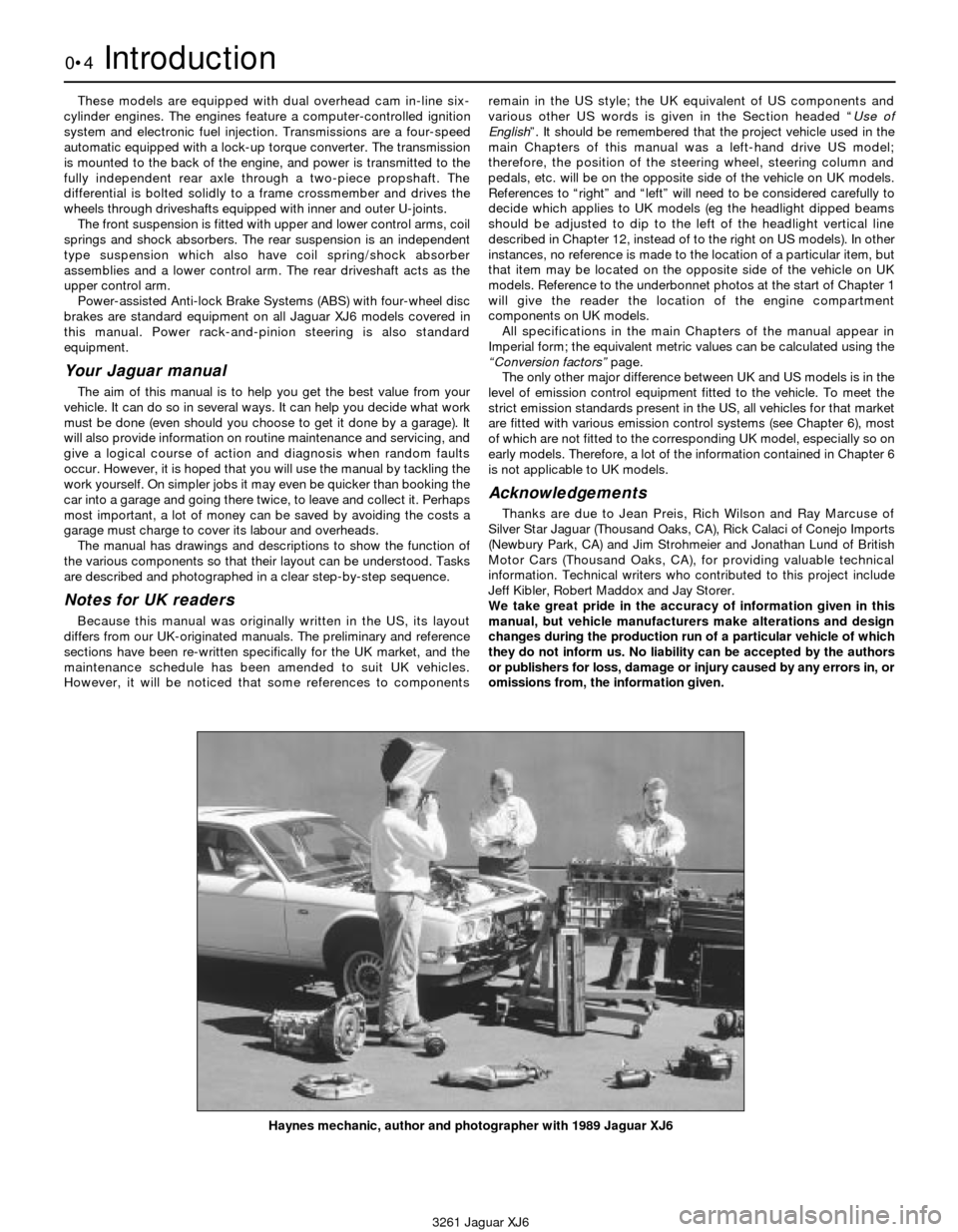
Haynes mechanic, author and photographer with 1989 Jaguar XJ6
Page 5 of 227
3261 Jaguar XJ6
Safety first!0•5
Working on your car can be dangerous.
This page shows just some of the potential
risks and hazards, with the aim of creating a
safety-conscious attitude.
General hazards
Scalding
• Don’t remove the radiator or expansion
tank cap while the engine is hot.
• Engine oil, automatic transmission fluid or
power steering fluid may also be dangerously
hot if the engine has recently been running.
Burning
• Beware of burns from the exhaust system
and from any part of the engine. Brake discs
and drums can also be extremely hot
immediately after use.
Crushing
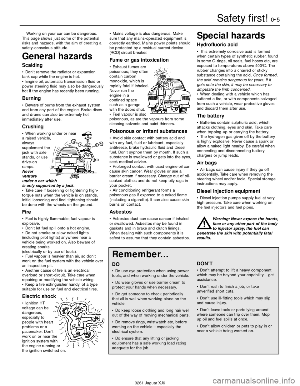
• When working under or near
a raised vehicle,
always
supplement the
jack with axle
stands, or use
drive-on
ramps.
Never
venture
under a car which
is only supported by a jack.
• Take care if loosening or tightening high-
torque nuts when the vehicle is on stands.
Initial loosening and final tightening should
be done with the wheels on the ground.
Fire
• Fuel is highly flammable; fuel vapour is
explosive.
• Don’t let fuel spill onto a hot engine.
• Do not smoke or allow naked lights
(including pilot lights) anywhere near a
vehicle being worked on. Also beware of
creating sparks
(electrically or by use of tools).
• Fuel vapour is heavier than air, so don’t
work on the fuel system with the vehicle over
an inspection pit.
• Another cause of fire is an electrical
overload or short-circuit. Take care when
repairing or modifying the vehicle wiring.
• Keep a fire extinguisher handy, of a type
suitable for use on fuel and electrical fires.
Electric shock
• Ignition HT
voltage can be
dangerous,
especially to
people with heart
problems or a
pacemaker. Don’t
work on or near the
ignition system with
the engine running or
the ignition switched on.• Mains voltage is also dangerous. Make
sure that any mains-operated equipment is
correctly earthed. Mains power points should
be protected by a residual current device
(RCD) circuit breaker.
Fume or gas intoxication
• Exhaust fumes are
poisonous; they often
contain carbon
monoxide, which is
rapidly fatal if inhaled.
Never run the
engine in a
confined space
such as a garage
with the doors shut.
• Fuel vapour is also
poisonous, as are the vapours from some
cleaning solvents and paint thinners.
Poisonous or irritant substances
• Avoid skin contact with battery acid and
with any fuel, fluid or lubricant, especially
antifreeze, brake hydraulic fluid and Diesel
fuel. Don’t syphon them by mouth. If such a
substance is swallowed or gets into the eyes,
seek medical advice.
• Prolonged contact with used engine oil can
cause skin cancer. Wear gloves or use a
barrier cream if necessary. Change out of oil-
soaked clothes and do not keep oily rags in
your pocket.
• Air conditioning refrigerant forms a
poisonous gas if exposed to a naked flame
(including a cigarette). It can also cause skin
burns on contact.
Asbestos
• Asbestos dust can cause cancer if inhaled
or swallowed. Asbestos may be found in
gaskets and in brake and clutch linings.
When dealing with such components it is
safest to assume that they contain asbestos.
Special hazards
Hydrofluoric acid
• This extremely corrosive acid is formed
when certain types of synthetic rubber, found
in some O-rings, oil seals, fuel hoses etc, are
exposed to temperatures above 400
0C. The
rubber changes into a charred or sticky
substance containing the acid. Once formed,
the acid remains dangerous for years. If it
gets onto the skin, it may be necessary to
amputate the limb concerned.
• When dealing with a vehicle which has
suffered a fire, or with components salvaged
from such a vehicle, wear protective gloves
and discard them after use.
The battery
• Batteries contain sulphuric acid, which
attacks clothing, eyes and skin. Take care
when topping-up or carrying the battery.
• The hydrogen gas given off by the battery
is highly explosive. Never cause a spark or
allow a naked light nearby. Be careful when
connecting and disconnecting battery
chargers or jump leads.
Air bags
• Air bags can cause injury if they go off
accidentally. Take care when removing the
steering wheel and/or facia. Special storage
instructions may apply.
Diesel injection equipment
• Diesel injection pumps supply fuel at very
high pressure. Take care when working on
the fuel injectors and fuel pipes.
Warning: Never expose the hands,
face or any other part of the body
to injector spray; the fuel can
penetrate the skin with potentially fatal
results.
Remember...
DO
• Do use eye protection when using power
tools, and when working under the vehicle.
• Do wear gloves or use barrier cream to
protect your hands when necessary.
• Do get someone to check periodically
that all is well when working alone on the
vehicle.
• Do keep loose clothing and long hair well
out of the way of moving mechanical parts.
• Do remove rings, wristwatch etc, before
working on the vehicle – especially the
electrical system.
• Do ensure that any lifting or jacking
equipment has a safe working load rating
adequate for the job.
A few tips
DON’T
• Don’t attempt to lift a heavy component
which may be beyond your capability – get
assistance.
• Don’t rush to finish a job, or take
unverified short cuts.
• Don’t use ill-fitting tools which may slip
and cause injury.
• Don’t leave tools or parts lying around
where someone can trip over them. Mop
up oil and fuel spills at once.
• Don’t allow children or pets to play in or
near a vehicle being worked on.
Page 9 of 227
3261 Jaguar XJ6
Roadside repairs0•9
When all else fails, you may find yourself
having to get a tow home – or of course you
may be helping somebody else. Long-distance
recovery should only be done by a garage or
breakdown service. For shorter distances, DIY
towing using another car is easy enough, but
observe the following points:
MUse a proper tow-rope – they are not
expensive. The vehicle being towed must
display an ‘ON TOW’ sign in its rear window.
MAlways turn the ignition key to the ‘on’
position when the vehicle is being towed, so
that the steering lock is released, and that the
direction indicator and brake lights will work.
MOnly attach the tow-rope to the towing
eyes provided. On some models with energy-
absorbing bumpers there are no front towing
eyes; on these vehicles the tow-rope shouldbe attached around the rear arm of the lower
control arm so that the rope passes on the
inside of the coil spring.
MBefore being towed, release the handbrake
and select neutral on the transmission.
MNote that greater-than-usual pedal
pressure will be required to operate the
brakes, since the vacuum servo unit is only
operational with the engine running.
MOn models with power steering, greater-
than-usual steering effort will also be required.
MThe driver of the car being towed must
keep the tow-rope taut at all times to avoid
snatching.
MMake sure that both drivers know the route
before setting off.
MOnly drive at moderate speeds and keep
the distance towed to a minimum. Drivesmoothly and allow plenty of time for slowing
down at junctions.
MOn models with automatic transmission,
special precautions apply. If in doubt, do not
tow, or transmission damage may result.
Caution: On models with automatic
transmission, if the vehicle is to be towed
with its rear wheels on the ground, and
extra 1.7 litres of fluid should be added to
the transmission, prior to towing (this extra
fluid must be drained before driving the
vehicle). Even with the extra fluid added to
the transmission, do not tow the vehicle at
speeds in excess of 30 mph (50 kmh) or for
a distance of greater than 15 miles (25 km).
If towing speed/distance are to exceed
these limits, then the vehicle must be
towed with its rear wheels off the ground.
Towing
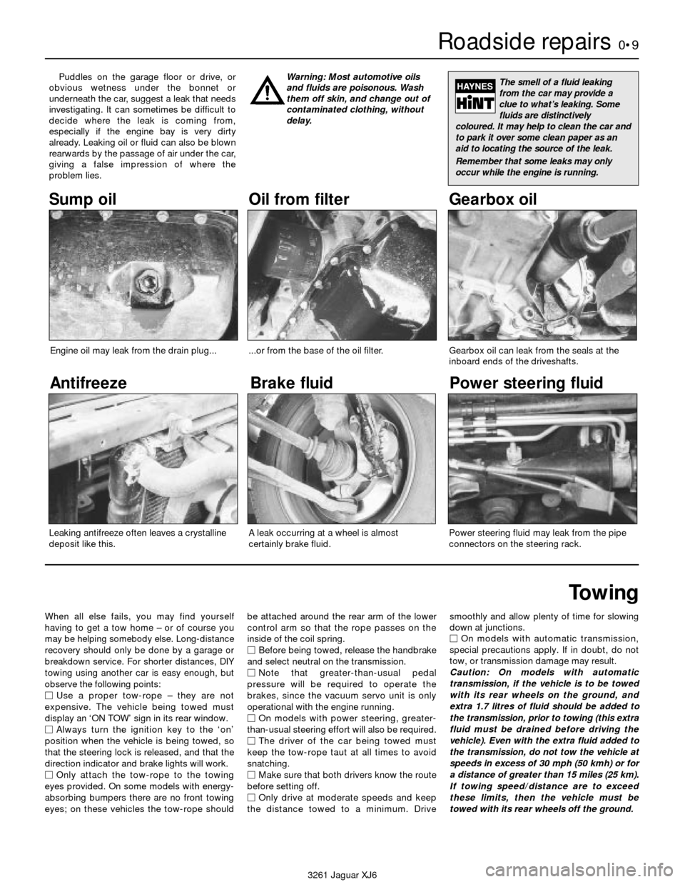
Puddles on the garage floor or drive, or
obvious wetness under the bonnet or
underneath the car, suggest a leak that needs
investigating. It can sometimes be difficult to
decide where the leak is coming from,
especially if the engine bay is very dirty
already. Leaking oil or fluid can also be blown
rearwards by the passage of air under the car,
giving a false impression of where the
problem lies.Warning: Most automotive oils
and fluids are poisonous. Wash
them off skin, and change out of
contaminated clothing, without
delay.The smell of a fluid leaking
from the car may provide a
clue to what’s leaking. Some
fluids are distinctively
coloured. It may help to clean the car and
to park it over some clean paper as an
aid to locating the source of the leak.
Remember that some leaks may only
occur while the engine is running.
Sump oil Gearbox oil
Brake fluid
Power steering fluid
Oil from filter
Antifreeze
Engine oil may leak from the drain plug......or from the base of the oil filter.
Leaking antifreeze often leaves a crystalline
deposit like this.Gearbox oil can leak from the seals at the
inboard ends of the driveshafts.
A leak occurring at a wheel is almost
certainly brake fluid.Power steering fluid may leak from the pipe
connectors on the steering rack.
Page 14 of 227
3261 Jaguar XJ6
0•14Weekly checks
Tyre condition and pressure
It is very important that tyres are in good
condition, and at the correct pressure - having
a tyre failure at any speed is highly dangerous.
Tyre wear is influenced by driving style - harsh
braking and acceleration, or fast cornering,
will all produce more rapid tyre wear. As a
general rule, the front tyres wear out faster
than the rears. Interchanging the tyres from
front to rear ("rotating" the tyres) may result in
more even wear. However, if this is
completely effective, you may have the
expense of replacing all four tyres at once!
Remove any nails or stones embedded in the
tread before they penetrate the tyre to cause
deflation. If removal of a nail does reveal thatthe tyre has been punctured, refit the nail so
that its point of penetration is marked. Then
immediately change the wheel, and have the
tyre repaired by a tyre dealer.
Regularly check the tyres for damage in the
form of cuts or bulges, especially in the
sidewalls. Periodically remove the wheels,
and clean any dirt or mud from the inside and
outside surfaces. Examine the wheel rims for
signs of rusting, corrosion or other damage.
Light alloy wheels are easily damaged by
"kerbing" whilst parking; steel wheels may
also become dented or buckled. A new wheel
is very often the only way to overcome severe
damage.New tyres should be balanced when they are
fitted, but it may become necessary to re-
balance them as they wear, or if the balance
weights fitted to the wheel rim should fall off.
Unbalanced tyres will wear more quickly, as
will the steering and suspension components.
Wheel imbalance is normally signified by
vibration, particularly at a certain speed
(typically around 50 mph). If this vibration is
felt only through the steering, then it is likely
that just the front wheels need balancing. If,
however, the vibration is felt through the
whole car, the rear wheels could be out of
balance. Wheel balancing should be carried
out by a tyre dealer or garage.
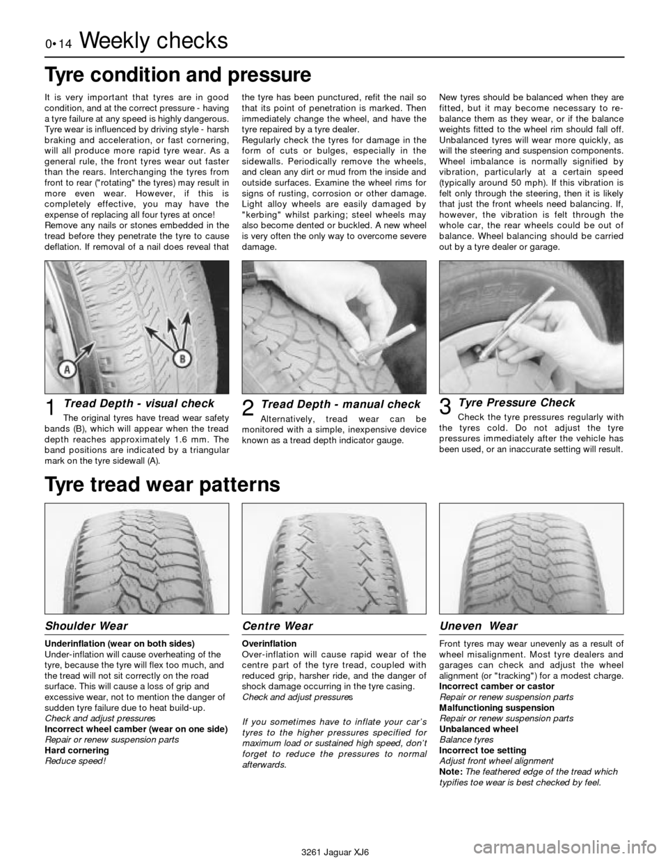
Tread Depth - visual check
The original tyres have tread wear safety
bands (B), which will appear when the tread
depth reaches approximately 1.6 mm. The
band positions are indicated by a triangular
mark on the tyre sidewall (A).1Tread Depth - manual check
Alternatively, tread wear can be
monitored with a simple, inexpensive device
known as a tread depth indicator gauge.2Tyre Pressure Check
Check the tyre pressures regularly with
the tyres cold. Do not adjust the tyre
pressures immediately after the vehicle has
been used, or an inaccurate setting will result.3
Tyre tread wear patterns
Shoulder Wear
Underinflation (wear on both sides)
Under-inflation will cause overheating of the
tyre, because the tyre will flex too much, and
the tread will not sit correctly on the road
surface. This will cause a loss of grip and
excessive wear, not to mention the danger of
sudden tyre failure due to heat build-up.
Check and adjust pressures
Incorrect wheel camber (wear on one side)
Repair or renew suspension parts
Hard cornering
Reduce speed!
Centre Wear
Overinflation
Over-inflation will cause rapid wear of the
centre part of the tyre tread, coupled with
reduced grip, harsher ride, and the danger of
shock damage occurring in the tyre casing.
Check and adjust pressures
If you sometimes have to inflate your car’s
tyres to the higher pressures specified for
maximum load or sustained high speed, don’t
forget to reduce the pressures to normal
afterwards.
Uneven Wear
Front tyres may wear unevenly as a result of
wheel misalignment. Most tyre dealers and
garages can check and adjust the wheel
alignment (or "tracking") for a modest charge.
Incorrect camber or castor
Repair or renew suspension parts
Malfunctioning suspension
Repair or renew suspension parts
Unbalanced wheel
Balance tyres
Incorrect toe setting
Adjust front wheel alignment
Note: The feathered edge of the tread which
typifies toe wear is best checked by feel.
Page 27 of 227
leak be found, renew the offending gasket or
oil seal by referring to the appropriate
Chapters in this manual.
2Also check the security and condition of all
the engine-related pipes and hoses. Ensure
that all cable ties or securing clips are in place
and in good condition. Clips which are broken
or missing can lead to chafing of the hoses,
pipes or wiring, which could cause more
serious problems in the future.
3Carefully check the radiator hoses and
heater hoses along their entire length. Renew
any hose which is cracked, swollen or
deteriorated. Cracks will show up better if
the hose is squeezed. Pay close attention
to the hose clips that secure the hoses to the
cooling system components. Hose clips can
pinch and puncture hoses, resulting in cooling
system leaks.
4Inspect all the cooling system components
(hoses, joint faces etc.) for leaks. A leak in the
cooling system will usually show up as white-
or rust-coloured deposits on the area
adjoining the leak. Where any problems of this
nature are found on system components,
renew the component or gasket with
reference to Chapter 3.
5From within the engine compartment,
check the security of all fuel hose attachments
and pipe unions, and inspect the fuel hoses
and vacuum hoses for kinks, chafing and
deterioration.
6Also check the condition of the power
steering fluid hoses and pipes.
8 Automatic transmission
fluid level check
1
1The level of the automatic transmission fluid
should be carefully maintained. Low fluid level
can lead to slipping or loss of drive, while
overfilling can cause foaming, loss of fluid and
transmission damage.
2The transmission fluid level should only be
checked when the transmission is at its
normal operating temperature.
Caution: If the vehicle has just been driven
for a long time at high speed or in city
traffic in hot weather, or if it has been
pulling a trailer, an accurate fluid level
reading cannot be obtained. Allow the fluid
to cool down for about 30 minutes.
3If the vehicle has not been driven, park the
vehicle on level ground, set the handbrake,
then start the engine and bring it to operating
temperature. While the engine is idling,
depress the brake pedal and move the
selector lever through all the gear ranges,
beginning and ending in Park.
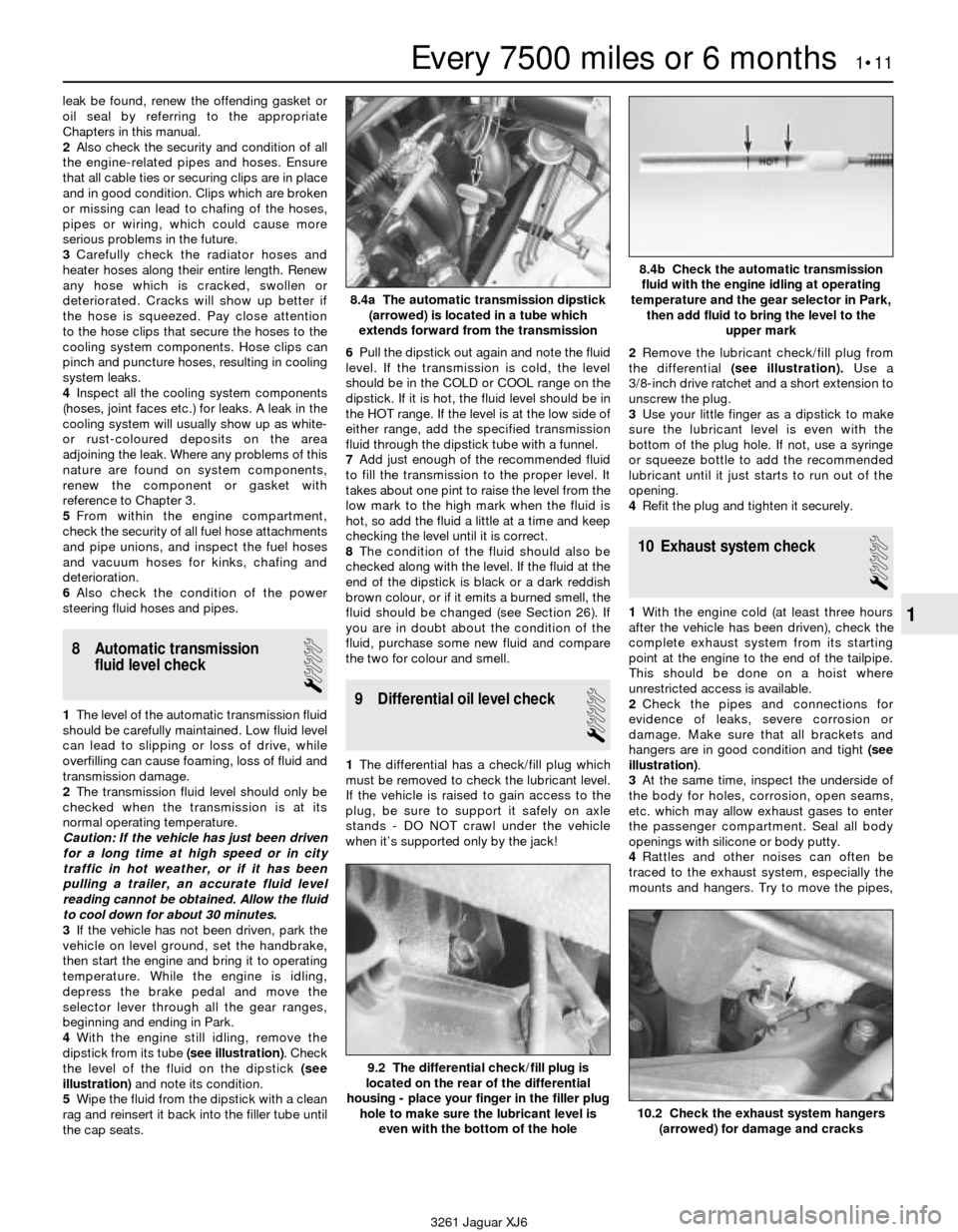
4With the engine still idling, remove the
dipstick from its tube (see illustration). Check
the level of the fluid on the dipstick (see
illustration)and note its condition.
5Wipe the fluid from the dipstick with a clean
rag and reinsert it back into the filler tube until
the cap seats.6Pull the dipstick out again and note the fluid
level. If the transmission is cold, the level
should be in the COLD or COOL range on the
dipstick. If it is hot, the fluid level should be in
the HOT range. If the level is at the low side of
either range, add the specified transmission
fluid through the dipstick tube with a funnel.
7Add just enough of the recommended fluid
to fill the transmission to the proper level. It
takes about one pint to raise the level from the
low mark to the high mark when the fluid is
hot, so add the fluid a little at a time and keep
checking the level until it is correct.
8The condition of the fluid should also be
checked along with the level. If the fluid at the
end of the dipstick is black or a dark reddish
brown colour, or if it emits a burned smell, the
fluid should be changed (see Section 26). If
you are in doubt about the condition of the
fluid, purchase some new fluid and compare
the two for colour and smell.9 Differential oil level check
1
1The differential has a check/fill plug which
must be removed to check the lubricant level.
If the vehicle is raised to gain access to the
plug, be sure to support it safely on axle
stands - DO NOT crawl under the vehicle
when it’s supported only by the jack!2Remove the lubricant check/fill plug from
the differential (see illustration).Use a
3/8-inch drive ratchet and a short extension to
unscrew the plug.
3Use your little finger as a dipstick to make
sure the lubricant level is even with the
bottom of the plug hole. If not, use a syringe
or squeeze bottle to add the recommended
lubricant until it just starts to run out of the
opening.
4Refit the plug and tighten it securely.
10 Exhaust system check
1
1With the engine cold (at least three hours
after the vehicle has been driven), check the
complete exhaust system from its starting
point at the engine to the end of the tailpipe.
This should be done on a hoist where
unrestricted access is available.
2Check the pipes and connections for
evidence of leaks, severe corrosion or
damage. Make sure that all brackets and
hangers are in good condition and tight (see
illustration).
3At the same time, inspect the underside of
the body for holes, corrosion, open seams,
etc. which may allow exhaust gases to enter
the passenger compartment. Seal all body
openings with silicone or body putty.
4Rattles and other noises can often be
traced to the exhaust system, especially the
mounts and hangers. Try to move the pipes,
Every 7500 miles or 6 months 1•11
1
9.2 The differential check/fill plug is
located on the rear of the differential
housing - place your finger in the filler plug
hole to make sure the lubricant level is
even with the bottom of the hole
10.2 Check the exhaust system hangers
(arrowed) for damage and cracks
3261 Jaguar XJ6
8.4a The automatic transmission dipstick
(arrowed) is located in a tube which
extends forward from the transmission
8.4b Check the automatic transmission
fluid with the engine idling at operating
temperature and the gear selector in Park,
then add fluid to bring the level to the
upper mark
Page 40 of 227
attached to the bolt threaded into the
front of the crankshaft. Apply pressure on
the bolt in a clockwise direction only.
Never turn the bolt anti-clockwise.
b) A remote starter switch, which may save
some time, can also be used. Follow the
instructions included with the switch.
Once the piston is close to TDC, use a
socket and ratchet as described in the
previous paragraph.
c) If an assistant is available to turn the
ignition switch to the Start position in
short bursts, you can get the piston close
to TDC without a remote starter switch.
Make sure your assistant is out of the car,
away from the ignition switch, then use a
socket and ratchet as described in
Paragraph a) to complete the procedure.
5Note the position of the terminal for the
number one spark plug lead on the distributor
cap. If the terminal isn’t marked, follow the
plug lead from the number one cylinder spark
plug to the cap.
6Use a felt-tip pen or chalk to make a mark
on the distributor body directly under the
number one terminal (see Chapter 5).
7Detach the cap from the distributor and set
it aside (see Chapter 1 if necessary).
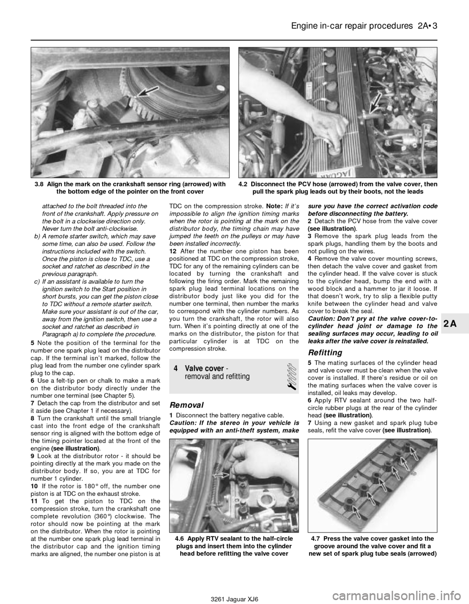
8Turn the crankshaft until the small triangle
cast into the front edge of the crankshaft
sensor ring is aligned with the bottom edge of
the timing pointer located at the front of the
engine(see illustration).
9Look at the distributor rotor - it should be
pointing directly at the mark you made on the
distributor body. If so, you are at TDC for
number 1 cylinder.
10If the rotor is 180° off, the number one
piston is at TDC on the exhaust stroke.
11To get the piston to TDC on the
compression stroke, turn the crankshaft one
complete revolution (360°) clockwise. The
rotor should now be pointing at the mark
on the distributor. When the rotor is pointing
at the number one spark plug lead terminal in
the distributor cap and the ignition timing
marks are aligned, the number one piston is atTDC on the compression stroke. Note:If it’s
impossible to align the ignition timing marks
when the rotor is pointing at the mark on the
distributor body, the timing chain may have
jumped the teeth on the pulleys or may have
been installed incorrectly.
12After the number one piston has been
positioned at TDC on the compression stroke,
TDC for any of the remaining cylinders can be
located by turning the crankshaft and
following the firing order. Mark the remaining
spark plug lead terminal locations on the
distributor body just like you did for the
number one terminal, then number the marks
to correspond with the cylinder numbers. As
you turn the crankshaft, the rotor will also
turn. When it’s pointing directly at one of the
marks on the distributor, the piston for that
particular cylinder is at TDC on the
compression stroke.
4 Valve cover-
removal and refitting
1
Removal
1Disconnect the battery negative cable.
Caution: If the stereo in your vehicle is
equipped with an anti-theft system, makesure you have the correct activation code
before disconnecting the battery.
2Detach the PCV hose from the valve cover
(see illustration).
3Remove the spark plug leads from the
spark plugs, handling them by the boots and
not pulling on the wires.
4Remove the valve cover mounting screws,
then detach the valve cover and gasket from
the cylinder head. If the valve cover is stuck
to the cylinder head, bump the end with a
wood block and a hammer to jar it loose. If
that doesn’t work, try to slip a flexible putty
knife between the cylinder head and valve
cover to break the seal.
Caution: Don’t pry at the valve cover-to-
cylinder head joint or damage to the
sealing surfaces may occur, leading to oil
leaks after the valve cover is reinstalled.
Refitting
5The mating surfaces of the cylinder head
and valve cover must be clean when the valve
cover is installed. If there’s residue or oil on
the mating surfaces when the valve cover is
installed, oil leaks may develop.
6Apply RTV sealant around the two half-
circle rubber plugs at the rear of the cylinder
head (see illustration).
7Using a new gasket and spark plug tube
seals, refit the valve cover (see illustration).
Engine in-car repair procedures 2A•3
2A
4.6 Apply RTV sealant to the half-circle
plugs and insert them into the cylinder
head before refitting the valve cover4.7 Press the valve cover gasket into the
groove around the valve cover and fit a
new set of spark plug tube seals (arrowed)
3261 Jaguar XJ6 3.8 Align the mark on the crankshaft sensor ring (arrowed) with
the bottom edge of the pointer on the front cover
4.2 Disconnect the PCV hose (arrowed) from the valve cover, then
pull the spark plug leads out by their boots, not the leads
Page 48 of 227

12Remove the four bolts in each camshaft
inner sprocket (see illustration). The bolts are
secured by sheetmetal “washer” plates. Bend
down the locking tabs with a hammer and
screwdriver tip to remove the bolts.
Caution: Stuff rags below the sprockets
while removing the bolts to prevent a bolt
from falling down into the front cover.
13Remove the two bolts retaining the upper
chain guide to the cylinder head (see
illustration).
14Pull the inner sprockets from each
camshaft (see illustration). Each camshaft
sprocket is comprised of an inner and outer,
each with a set of fine splines that lock them
together. The outer sprockets, with the teeth,
can rotate on the camshafts until the inner
sprocket bolts are tightened.
15Pull the outer sprockets from the
camshafts and allow the chain slacken.
16At this point the camshafts can be
carefully lifted straight up and off the cylinder
head. Take care not to nick any of the lobes or
journals during removal.
17Use a magnet to remove the lifters,
keeping them in order in a divided, numbered
box (see illustration). They must be returned
to their original location if reusing the original
camshafts!
18Removing the lifters exposes the
adjusting shims, sitting in a pocket in eachvalve spring retainer (see illustration). Keep
the shims with their matching lifters. Measure
the thickness of each shim with a micrometer
and record the measurements.
Inspection
19After the camshaft has been removed
from the engine, cleaned with solvent and
dried, inspect the bearing journals for uneven
wear, pitting and evidence of seizure. If the
journals are damaged, the bearing surfaces in
the cylinder head and caps may be damaged
as well, requiring renewal of the cylinder head.
20Measure the bearing journals with a
micrometer to determine if they are excessivelyworn or out-of-round (see illustration).
Compare the measurements to Specifications.
21Check the camshaft lobes for heat
discolouration, score marks, chipped areas,
pitting and uneven wear. Measure the lobe
heights with a micrometer and record the
measurements (see illustrations). If there is
variance of more than 0.005-inch, the
camshaft and lifters must be renewed. If the
lobes are in good condition, the camshaft can
be reused.
22Inspect the top, bottom and side surfaces
of the lifters for wear, grooving or scoring. If
the lifters are damaged, the camshaft and its
lifters must be renewed as a set.
Engine in-car repair procedures 2A•11
2A
10.13 Remove the two bolts and the upper
timing chain guide (arrowed)10.14 Pull the inner sprocket from the
outer sprocket of each camshaft
10.17 A magnet can be used to remove
the lifters (arrowed)10.18 The valve adjustment shims
(arrowed) fit into a pocket in the valve
spring retainer - use a magnet to remove
the shims and keep them with their
respective lifters10.20 Measure the bearing journals with a
micrometer to check diameter - measure
at several places around the journal to
check for taper or out-of-round
3261 Jaguar XJ6 10.12 Bend back the locking tabs
(arrowed) and remove the camshaft
sprocket bolts
10.21a Measure the camshaft lobe at its
greatest dimension . . .10.21b . . . and subtract the camshaft lobe
diameter at its smallest dimension to
obtain the lobe lift
Page 57 of 227
Engine block
Deck warpage limit . . . . . . . . . . . . . . . . . . . . . . . . . . . . . . . . . . . . . . . . . 0.076 mm (0.003 inch)
Cylinder bore diameter
Standard
Size group A . . . . . . . . . . . . . . . . . . . . . . . . . . . . . . . . . . . . . . . . . . 90.990 to 91.003 mm (3.5823 to 3.5828 inches)
Size group B . . . . . . . . . . . . . . . . . . . . . . . . . . . . . . . . . . . . . . . . . . 91.005 to 91.018 mm (3.5829 to 3.5834 inches)
Oversize
0.25 mm (0.010 inch) OS . . . . . . . . . . . . . . . . . . . . . . . . . . . . . . . . 91.259 to 91.272 mm (3.5929 to 3.5934 inches)
0.50 mm (0.020 inch) OS . . . . . . . . . . . . . . . . . . . . . . . . . . . . . . . . 91.513 to 91.526 mm (3.6029 to 3.6034 inches)
Pistons and rings
Piston-to-bore clearance . . . . . . . . . . . . . . . . . . . . . . . . . . . . . . . . . . . . 0.017 to 0.043 mm (0.0007 to 0.0017 inch)
Piston ring end gap
No.1 (top) compression ring . . . . . . . . . . . . . . . . . . . . . . . . . . . . . . . . 0.40 to 0.66 mm (0.016 to 0.026 inch)
No.2 (middle) compression ring . . . . . . . . . . . . . . . . . . . . . . . . . . . . . 0.40 to 0.66 mm (0.016 to 0.026 inch)
Oil ring . . . . . . . . . . . . . . . . . . . . . . . . . . . . . . . . . . . . . . . . . . . . . . . . . 0.30 to 0.55 mm (0.012 to 0.022 inch)
Piston ring groove clearance
No. 1 (top) compression ring . . . . . . . . . . . . . . . . . . . . . . . . . . . . . . . 0.040 to 0.076 mm (0.0016 to 0.0030 inch)
No. 2 (middle) compression ring . . . . . . . . . . . . . . . . . . . . . . . . . . . . . 0.040 to 0.076 mm (0.0016 to 0.0030 inch)
Torque wrench settingsNm lbf ft
Main bearing cap bolts . . . . . . . . . . . . . . . . . . . . . . . . . . . . . . . . . . . . . . 136 to 142 100 to 105
Connecting rod cap nuts . . . . . . . . . . . . . . . . . . . . . . . . . . . . . . . . . . . . 50 to 60 37 to 44
* Note:Refer to Part A for additional torque specifications.
2B•2 Engine removal and overhaul procedures
3261 Jaguar XJ6
1 General information
Included in this portion of Chapter 2 are the
general overhaul procedures for the cylinder
head and internal engine components.
The information ranges from advice
concerning preparation for an overhaul and
the purchase of replacement parts to detailed,
step-by-step procedures covering removal
and refitting of internal engine components
and the inspection of parts.
The following Sections have been written
based on the assumption that the engine has
been removed from the vehicle. For
information concerning in-vehicle engine
repair, as well as removal and refitting of the
external components necessary for the
overhaul, see Part A of this Chapter.
The Specifications included in this Part are
only those necessary for the inspection and
overhaul procedures which follow. Refer to
Part A for additional Specifications.
2 Engine overhaul-
general information
It’s not always easy to determine when, or if,
an engine should be completely overhauled,
as a number of factors must be considered.
High mileage is not necessarily an indication
that an overhaul is needed, while low mileage
doesn’t preclude the need for an overhaul.
Frequency of servicing is probably the most
important consideration. An engine that’s had
regular and frequent oil and filter changes, as
well as other required maintenance, will most
likely give many thousands of miles of reliableservice. Conversely, a neglected engine may
require an overhaul very early in its life.
Excessive oil consumption is an indication
that piston rings, valve seals and/or valve
guides are in need of attention. Make sure that
oil leaks aren’t responsible before deciding
that the rings and/or guides are bad. Perform a
cylinder compression check to determine the
extent of the work required (see Section 4).
Also check the vacuum readings under various
conditions (see Section 3).
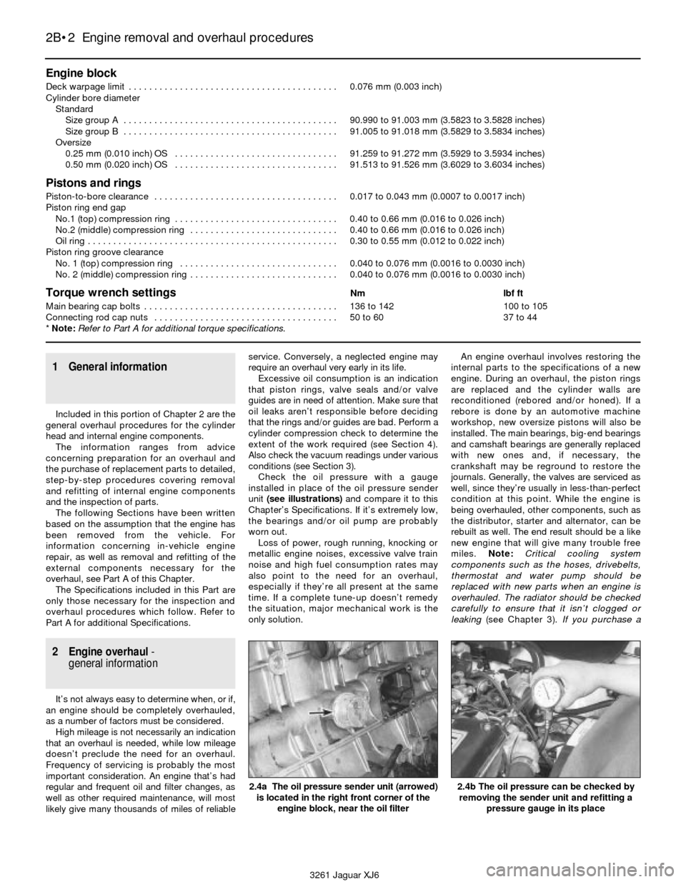
Check the oil pressure with a gauge
installed in place of the oil pressure sender
unit (see illustrations)and compare it to this
Chapter’s Specifications. If it’s extremely low,
the bearings and/or oil pump are probably
worn out.
Loss of power, rough running, knocking or
metallic engine noises, excessive valve train
noise and high fuel consumption rates may
also point to the need for an overhaul,
especially if they’re all present at the same
time. If a complete tune-up doesn’t remedy
the situation, major mechanical work is the
only solution.An engine overhaul involves restoring the
internal parts to the specifications of a new
engine. During an overhaul, the piston rings
are replaced and the cylinder walls are
reconditioned (rebored and/or honed). If a
rebore is done by an automotive machine
workshop, new oversize pistons will also be
installed. The main bearings, big-end bearings
and camshaft bearings are generally replaced
with new ones and, if necessary, the
crankshaft may be reground to restore the
journals. Generally, the valves are serviced as
well, since they’re usually in less-than-perfect
condition at this point. While the engine is
being overhauled, other components, such as
the distributor, starter and alternator, can be
rebuilt as well. The end result should be a like
new engine that will give many trouble free
miles. Note:Critical cooling system
components such as the hoses, drivebelts,
thermostat and water pump should be
replaced with new parts when an engine is
overhauled. The radiator should be checked
carefully to ensure that it isn’t clogged or
leaking (see Chapter 3).If you purchase a
2.4a The oil pressure sender unit (arrowed)
is located in the right front corner of the
engine block, near the oil filter2.4b The oil pressure can be checked by
removing the sender unit and refitting a
pressure gauge in its place
Page 58 of 227
rebuilt engine or short block, some rebuilders
will not warranty their engines unless the
radiator has been professionally flushed. Also,
we don’t recommend overhauling the oil
pump - always refit a new one when an engine
is rebuilt.
Before beginning the engine overhaul, read
through the entire procedure to familiarise
yourself with the scope and requirements of
the job. Overhauling an engine isn’t difficult,
but it is time-consuming. Plan on the vehicle
being tied up for a minimum of two weeks,
especially if parts must be taken to an
automotive machine workshop for repair or
reconditioning. Check on availability of parts
and make sure that any necessary special
tools and equipment are obtained in advance.
Most work can be done with typical hand
tools, although a number of precision
measuring tools are required for inspecting
parts to determine if they must be renewed.
Often an automotive machine workshop will
handle the inspection of parts and offer
advice concerning reconditioning and
renewal. Note:Always wait until the engine
has been completely dismantled and all
components, especially the engine block,
have been inspected before deciding what
service and repair operations must be
performed by an automotive machine
workshop. Since the engine block’s condition
will be the major factor to consider when
determining whether to overhaul the original
engine or buy a rebuilt one, never purchase
parts or have machine work done on other
components until the engine block has been
thoroughly inspected. As a general rule, time
is the primary cost of an overhaul, so it
doesn’t pay to refit worn or substandard
parts.
If it turns out that a number of major
components are beyond reconditioning, it
may be cost effective to buy a factory-rebuilt
engine from a Jaguar dealership.
As a final note, to ensure maximum life and
minimum trouble from a rebuilt engine,
everything must be assembled with care in a
spotlessly-clean environment.
3 Vacuum gauge
diagnostic checks
2
A vacuum gauge provides valuable
information about what is going on in the
engine at a low cost. You can check for worn
rings or cylinder walls, leaking cylinder head or
intake manifold gaskets, incorrect carburettor
adjustments, restricted exhaust, stuck or
burned valves, weak valve springs, improper
ignition or valve timing and ignition problems.
Unfortunately, vacuum gauge readings are
easy to misinterpret, so they should be used
with other tests to confirm the diagnosis.
Both the absolute readings and the rate of
needle movement are important for accurate
interpretation. Most gauges measure vacuumin inches of mercury (in-Hg). As vacuum
increases (or atmospheric pressure decreases),
the reading will decrease. Also, for every
1000 foot increase in elevation above sea level;
the gauge readings will decrease about one
inch of mercury.
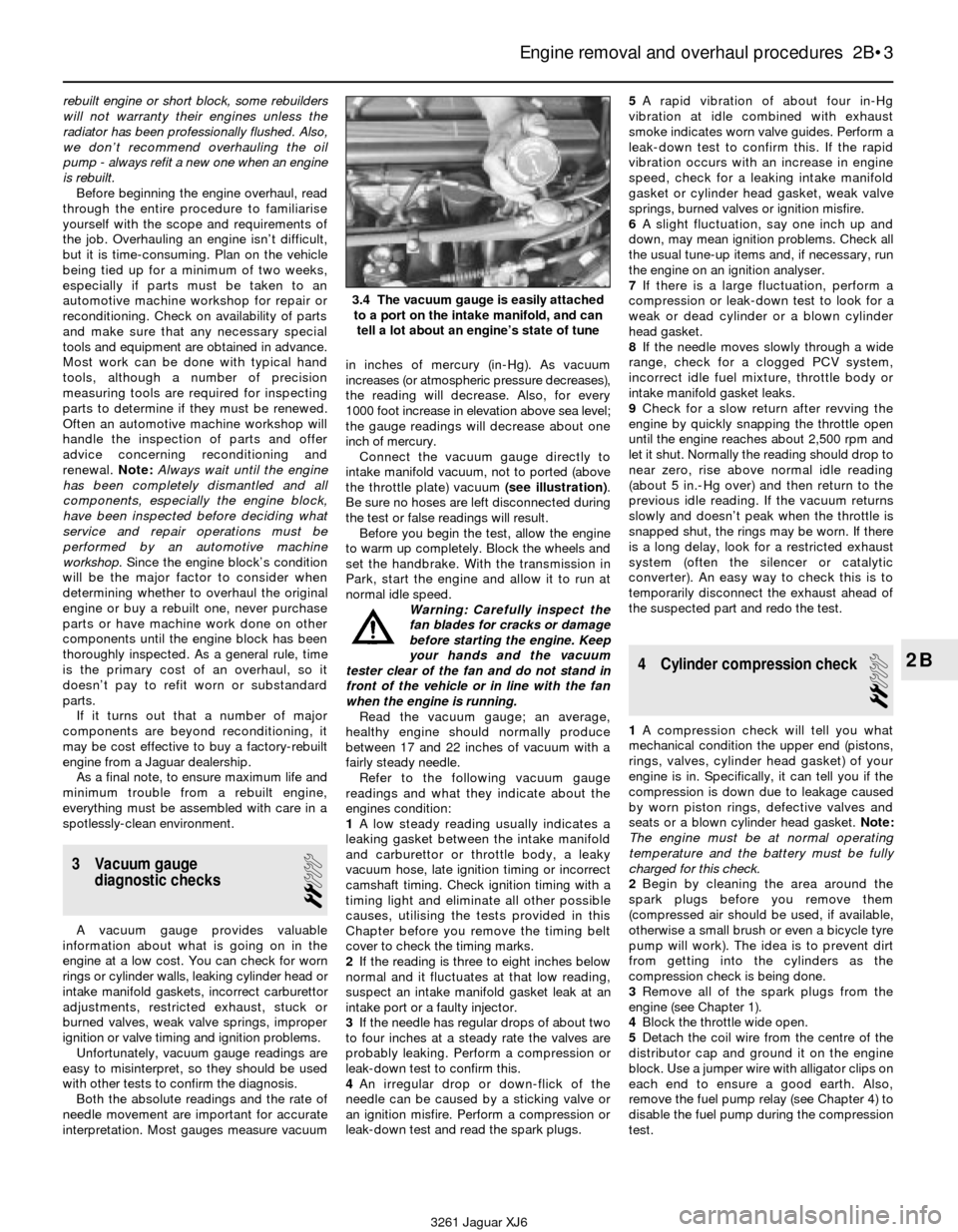
Connect the vacuum gauge directly to
intake manifold vacuum, not to ported (above
the throttle plate) vacuum (see illustration).
Be sure no hoses are left disconnected during
the test or false readings will result.
Before you begin the test, allow the engine
to warm up completely. Block the wheels and
set the handbrake. With the transmission in
Park, start the engine and allow it to run at
normal idle speed.
Warning: Carefully inspect the
fan blades for cracks or damage
before starting the engine. Keep
your hands and the vacuum
tester clear of the fan and do not stand in
front of the vehicle or in line with the fan
when the engine is running.
Read the vacuum gauge; an average,
healthy engine should normally produce
between 17 and 22 inches of vacuum with a
fairly steady needle.
Refer to the following vacuum gauge
readings and what they indicate about the
engines condition:
1A low steady reading usually indicates a
leaking gasket between the intake manifold
and carburettor or throttle body, a leaky
vacuum hose, late ignition timing or incorrect
camshaft timing. Check ignition timing with a
timing light and eliminate all other possible
causes, utilising the tests provided in this
Chapter before you remove the timing belt
cover to check the timing marks.
2If the reading is three to eight inches below
normal and it fluctuates at that low reading,
suspect an intake manifold gasket leak at an
intake port or a faulty injector.
3If the needle has regular drops of about two
to four inches at a steady rate the valves are
probably leaking. Perform a compression or
leak-down test to confirm this.
4An irregular drop or down-flick of the
needle can be caused by a sticking valve or
an ignition misfire. Perform a compression or
leak-down test and read the spark plugs.5A rapid vibration of about four in-Hg
vibration at idle combined with exhaust
smoke indicates worn valve guides. Perform a
leak-down test to confirm this. If the rapid
vibration occurs with an increase in engine
speed, check for a leaking intake manifold
gasket or cylinder head gasket, weak valve
springs, burned valves or ignition misfire.
6A slight fluctuation, say one inch up and
down, may mean ignition problems. Check all
the usual tune-up items and, if necessary, run
the engine on an ignition analyser.
7If there is a large fluctuation, perform a
compression or leak-down test to look for a
weak or dead cylinder or a blown cylinder
head gasket.
8If the needle moves slowly through a wide
range, check for a clogged PCV system,
incorrect idle fuel mixture, throttle body or
intake manifold gasket leaks.
9Check for a slow return after revving the
engine by quickly snapping the throttle open
until the engine reaches about 2,500 rpm and
let it shut. Normally the reading should drop to
near zero, rise above normal idle reading
(about 5 in.-Hg over) and then return to the
previous idle reading. If the vacuum returns
slowly and doesn’t peak when the throttle is
snapped shut, the rings may be worn. If there
is a long delay, look for a restricted exhaust
system (often the silencer or catalytic
converter). An easy way to check this is to
temporarily disconnect the exhaust ahead of
the suspected part and redo the test.
4 Cylinder compression check
2
1A compression check will tell you what
mechanical condition the upper end (pistons,
rings, valves, cylinder head gasket) of your
engine is in. Specifically, it can tell you if the
compression is down due to leakage caused
by worn piston rings, defective valves and
seats or a blown cylinder head gasket. Note:
The engine must be at normal operating
temperature and the battery must be fully
charged for this check.
2Begin by cleaning the area around the
spark plugs before you remove them
(compressed air should be used, if available,
otherwise a small brush or even a bicycle tyre
pump will work). The idea is to prevent dirt
from getting into the cylinders as the
compression check is being done.
3Remove all of the spark plugs from the
engine (see Chapter 1).
4Block the throttle wide open.
5Detach the coil wire from the centre of the
distributor cap and ground it on the engine
block. Use a jumper wire with alligator clips on
each end to ensure a good earth. Also,
remove the fuel pump relay (see Chapter 4) to
disable the fuel pump during the compression
test.
Engine removal and overhaul procedures 2B•3
2B
3.4 The vacuum gauge is easily attached
to a port on the intake manifold, and can
tell a lot about an engine’s state of tune
3261 Jaguar XJ6