Rack and pinion JAGUAR XJ6 1997 2.G Workshop Manual
[x] Cancel search | Manufacturer: JAGUAR, Model Year: 1997, Model line: XJ6, Model: JAGUAR XJ6 1997 2.GPages: 227, PDF Size: 7.2 MB
Page 4 of 227
These models are equipped with dual overhead cam in-line six-
cylinder engines. The engines feature a computer-controlled ignition
system and electronic fuel injection. Transmissions are a four-speed
automatic equipped with a lock-up torque converter. The transmission
is mounted to the back of the engine, and power is transmitted to the
fully independent rear axle through a two-piece propshaft. The
differential is bolted solidly to a frame crossmember and drives the
wheels through driveshafts equipped with inner and outer U-joints.
The front suspension is fitted with upper and lower control arms, coil
springs and shock absorbers. The rear suspension is an independent
type suspension which also have coil spring/shock absorber
assemblies and a lower control arm. The rear driveshaft acts as the
upper control arm.
Power-assisted Anti-lock Brake Systems (ABS) with four-wheel disc
brakes are standard equipment on all Jaguar XJ6 models covered in
this manual. Power rack-and-pinion steering is also standard
equipment.
Your Jaguar manual
The aim of this manual is to help you get the best value from your
vehicle. It can do so in several ways. It can help you decide what work
must be done (even should you choose to get it done by a garage). It
will also provide information on routine maintenance and servicing, and
give a logical course of action and diagnosis when random faults
occur. However, it is hoped that you will use the manual by tackling the
work yourself. On simpler jobs it may even be quicker than booking the
car into a garage and going there twice, to leave and collect it. Perhaps
most important, a lot of money can be saved by avoiding the costs a
garage must charge to cover its labour and overheads.
The manual has drawings and descriptions to show the function of
the various components so that their layout can be understood. Tasks
are described and photographed in a clear step-by-step sequence.
Notes for UK readers
Because this manual was originally written in the US, its layout
differs from our UK-originated manuals. The preliminary and reference
sections have been re-written specifically for the UK market, and the
maintenance schedule has been amended to suit UK vehicles.
However, it will be noticed that some references to componentsremain in the US style; the UK equivalent of US components and
various other US words is given in the Section headed “Use of
English”. It should be remembered that the project vehicle used in the
main Chapters of this manual was a left-hand drive US model;
therefore, the position of the steering wheel, steering column and
pedals, etc. will be on the opposite side of the vehicle on UK models.
References to “right” and “left” will need to be considered carefully to
decide which applies to UK models (eg the headlight dipped beams
should be adjusted to dip to the left of the headlight vertical line
described in Chapter 12, instead of to the right on US models). In other
instances, no reference is made to the location of a particular item, but
that item may be located on the opposite side of the vehicle on UK
models. Reference to the underbonnet photos at the start of Chapter 1
will give the reader the location of the engine compartment
components on UK models.
All specifications in the main Chapters of the manual appear in
Imperial form; the equivalent metric values can be calculated using the
“Conversion factors”page.
The only other major difference between UK and US models is in the
level of emission control equipment fitted to the vehicle. To meet the
strict emission standards present in the US, all vehicles for that market
are fitted with various emission control systems (see Chapter 6), most
of which are not fitted to the corresponding UK model, especially so on
early models. Therefore, a lot of the information contained in Chapter 6
is not applicable to UK models.
Acknowledgements
Thanks are due to Jean Preis, Rich Wilson and Ray Marcuse of
Silver Star Jaguar (Thousand Oaks, CA), Rick Calaci of Conejo Imports
(Newbury Park, CA) and Jim Strohmeier and Jonathan Lund of British
Motor Cars (Thousand Oaks, CA), for providing valuable technical
information. Technical writers who contributed to this project include
Jeff Kibler, Robert Maddox and Jay Storer.
We take great pride in the accuracy of information given in this
manual, but vehicle manufacturers make alterations and design
changes during the production run of a particular vehicle of which
they do not inform us. No liability can be accepted by the authors
or publishers for loss, damage or injury caused by any errors in, or
omissions from, the information given.
0•4Introduction
3261 Jaguar XJ6
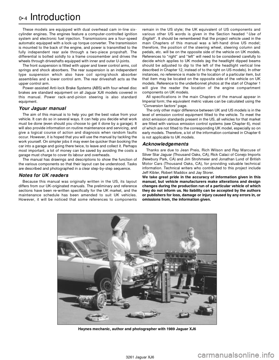
Haynes mechanic, author and photographer with 1989 Jaguar XJ6
Page 137 of 227
3261 Jaguar XJ6
10
Chapter 10
Suspension and steering systems
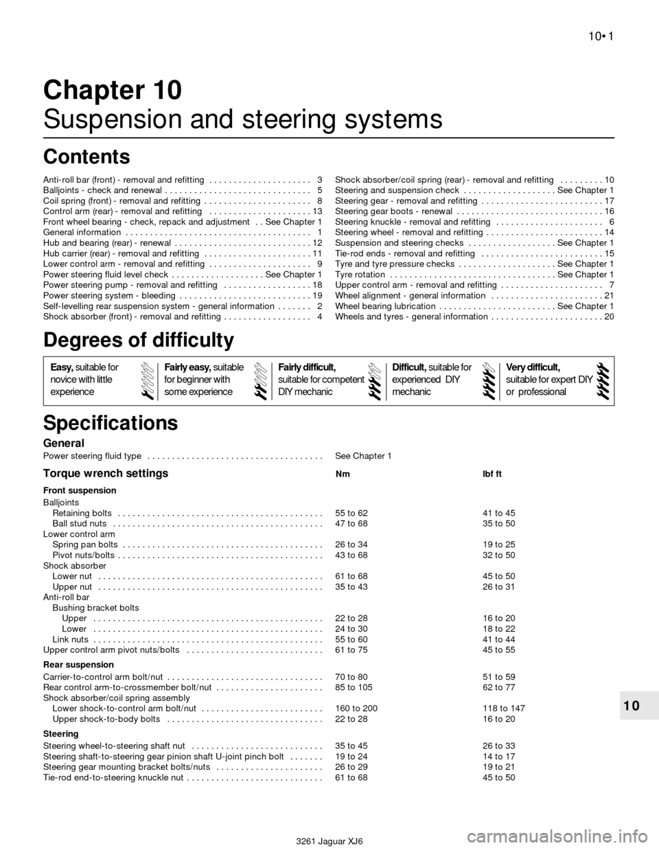
General
Power steering fluid type . . . . . . . . . . . . . . . . . . . . . . . . . . . . . . . . . . . . See Chapter 1
Torque wrench settingsNm lbf ft
Front suspension
Balljoints
Retaining bolts . . . . . . . . . . . . . . . . . . . . . . . . . . . . . . . . . . . . . . . . . . 55 to 62 41 to 45
Ball stud nuts . . . . . . . . . . . . . . . . . . . . . . . . . . . . . . . . . . . . . . . . . . . 47 to 68 35 to 50
Lower control arm
Spring pan bolts . . . . . . . . . . . . . . . . . . . . . . . . . . . . . . . . . . . . . . . . . 26 to 34 19 to 25
Pivot nuts/bolts . . . . . . . . . . . . . . . . . . . . . . . . . . . . . . . . . . . . . . . . . . 43 to 68 32 to 50
Shock absorber
Lower nut . . . . . . . . . . . . . . . . . . . . . . . . . . . . . . . . . . . . . . . . . . . . . . 61 to 68 45 to 50
Upper nut . . . . . . . . . . . . . . . . . . . . . . . . . . . . . . . . . . . . . . . . . . . . . . 35 to 43 26 to 31
Anti-roll bar
Bushing bracket bolts
Upper . . . . . . . . . . . . . . . . . . . . . . . . . . . . . . . . . . . . . . . . . . . . . . . 22 to 28 16 to 20
Lower . . . . . . . . . . . . . . . . . . . . . . . . . . . . . . . . . . . . . . . . . . . . . . . 24 to 30 18 to 22
Link nuts . . . . . . . . . . . . . . . . . . . . . . . . . . . . . . . . . . . . . . . . . . . . . . . 55 to 60 41 to 44
Upper control arm pivot nuts/bolts . . . . . . . . . . . . . . . . . . . . . . . . . . . . 61 to 75 45 to 55
Rear suspension
Carrier-to-control arm bolt/nut . . . . . . . . . . . . . . . . . . . . . . . . . . . . . . . . 70 to 80 51 to 59
Rear control arm-to-crossmember bolt/nut . . . . . . . . . . . . . . . . . . . . . . 85 to 105 62 to 77
Shock absorber/coil spring assembly
Lower shock-to-control arm bolt/nut . . . . . . . . . . . . . . . . . . . . . . . . . 160 to 200 118 to 147
Upper shock-to-body bolts . . . . . . . . . . . . . . . . . . . . . . . . . . . . . . . . 22 to 28 16 to 20
Steering
Steering wheel-to-steering shaft nut . . . . . . . . . . . . . . . . . . . . . . . . . . . 35 to 45 26 to 33
Steering shaft-to-steering gear pinion shaft U-joint pinch bolt . . . . . . . 19 to 24 14 to 17
Steering gear mounting bracket bolts/nuts . . . . . . . . . . . . . . . . . . . . . . 26 to 29 19 to 21
Tie-rod end-to-steering knuckle nut . . . . . . . . . . . . . . . . . . . . . . . . . . . . 61 to 68 45 to 50 Anti-roll bar (front) - removal and refitting . . . . . . . . . . . . . . . . . . . . . 3
Balljoints - check and renewal . . . . . . . . . . . . . . . . . . . . . . . . . . . . . . 5
Coil spring (front) - removal and refitting . . . . . . . . . . . . . . . . . . . . . . 8
Control arm (rear) - removal and refitting . . . . . . . . . . . . . . . . . . . . . 13
Front wheel bearing - check, repack and adjustment . . See Chapter 1
General information . . . . . . . . . . . . . . . . . . . . . . . . . . . . . . . . . . . . . . 1
Hub and bearing (rear) - renewal . . . . . . . . . . . . . . . . . . . . . . . . . . . . 12
Hub carrier (rear) - removal and refitting . . . . . . . . . . . . . . . . . . . . . . 11
Lower control arm - removal and refitting . . . . . . . . . . . . . . . . . . . . . 9
Power steering fluid level check . . . . . . . . . . . . . . . . . . . See Chapter 1
Power steering pump - removal and refitting . . . . . . . . . . . . . . . . . . 18
Power steering system - bleeding . . . . . . . . . . . . . . . . . . . . . . . . . . . 19
Self-levelling rear suspension system - general information . . . . . . . 2
Shock absorber (front) - removal and refitting . . . . . . . . . . . . . . . . . . 4Shock absorber/coil spring (rear) - removal and refitting . . . . . . . . . 10
Steering and suspension check . . . . . . . . . . . . . . . . . . . See Chapter 1
Steering gear - removal and refitting . . . . . . . . . . . . . . . . . . . . . . . . . 17
Steering gear boots - renewal . . . . . . . . . . . . . . . . . . . . . . . . . . . . . . 16
Steering knuckle - removal and refitting . . . . . . . . . . . . . . . . . . . . . . 6
Steering wheel - removal and refitting . . . . . . . . . . . . . . . . . . . . . . . . 14
Suspension and steering checks . . . . . . . . . . . . . . . . . . See Chapter 1
Tie-rod ends - removal and refitting . . . . . . . . . . . . . . . . . . . . . . . . . 15
Tyre and tyre pressure checks . . . . . . . . . . . . . . . . . . . . See Chapter 1
Tyre rotation . . . . . . . . . . . . . . . . . . . . . . . . . . . . . . . . . . See Chapter 1
Upper control arm - removal and refitting . . . . . . . . . . . . . . . . . . . . . 7
Wheel alignment - general information . . . . . . . . . . . . . . . . . . . . . . . 21
Wheel bearing lubrication . . . . . . . . . . . . . . . . . . . . . . . . See Chapter 1
Wheels and tyres - general information . . . . . . . . . . . . . . . . . . . . . . . 20
10•1
Specifications Contents
Easy,suitable for
novice with little
experienceFairly easy,suitable
for beginner with
some experienceFairly difficult,
suitable for competent
DIY mechanic
Difficult,suitable for
experienced DIY
mechanicVery difficult,
suitable for expert DIY
or professional
Degrees of difficulty
54321
Page 139 of 227
1 General information
Warning: Whenever any of the
suspension or steering fasteners
are loosened or removed, they
must be inspected and if
necessary, replaced with new ones of the
same part number or of original equipment
quality and design. Torque wrench settings
must be followed for proper reassembly
and component retention. Never attempt
to heat, straighten or weld any suspension
or steering component. Instead, renew any
bent or damaged part.
The front suspension (see illustrations)
consists of unequal-length upper and lower
control arms, shock absorbers and coil
springs. The upper ends of the shocks are
attached to the body; the lower ends
are attached to the lower control arms. The
upper ends of the coil springs are seated
against the suspension crossmember; the
lower ends are seated against removable
plates which are bolted to the lower control
arms. The steering knuckles are attached to
balljoints in the upper and lower control arms.
An anti-roll bar is attached to the suspension
crossmember with a pair of bushing brackets
and to the lower control arms via a connecting
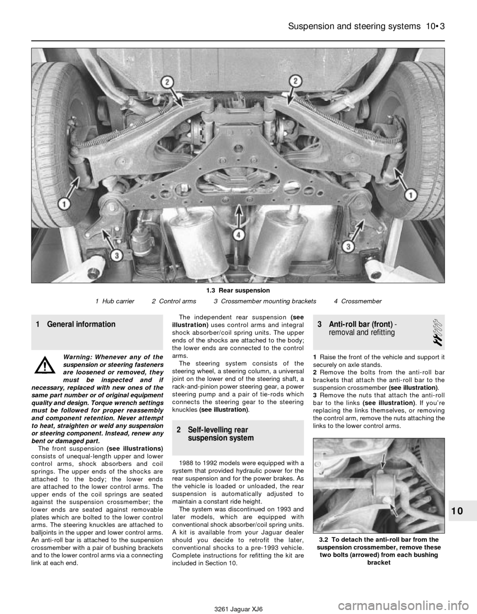
link at each end.The independent rear suspension (see
illustration)uses control arms and integral
shock absorber/coil spring units. The upper
ends of the shocks are attached to the body;
the lower ends are connected to the control
arms.
The steering system consists of the
steering wheel, a steering column, a universal
joint on the lower end of the steering shaft, a
rack-and-pinion power steering gear, a power
steering pump and a pair of tie-rods which
connects the steering gear to the steering
knuckles (see illustration).
2 Self-levelling rear
suspension system
1988 to 1992 models were equipped with a
system that provided hydraulic power for the
rear suspension and for the power brakes. As
the vehicle is loaded or unloaded, the rear
suspension is automatically adjusted to
maintain a constant ride height.
The system was discontinued on 1993 and
later models, which are equipped with
conventional shock absorber/coil spring units.
A kit is available from your Jaguar dealer
should you decide to retrofit the later,
conventional shocks to a pre-1993 vehicle.
Complete instructions for refitting the kit are
included in Section 10.
3 Anti-roll bar (front)-
removal and refitting
2
1Raise the front of the vehicle and support it
securely on axle stands.
2Remove the bolts from the anti-roll bar
brackets that attach the anti-roll bar to the
suspension crossmember (see illustration).
3Remove the nuts that attach the anti-roll
bar to the links (see illustration). If you’re
replacing the links themselves, or removing
the control arm, remove the nuts attaching the
links to the lower control arms.
Suspension and steering systems 10•3
10
1.3 Rear suspension
1 Hub carrier 2 Control arms 3 Crossmember mounting brackets 4 Crossmember
3.2 To detach the anti-roll bar from the
suspension crossmember, remove these
two bolts (arrowed) from each bushing
bracket
3261 Jaguar XJ6
Page 146 of 227

17 Steering gear-
removal and refitting
3
Warning: On models with an
airbag, do not apply excessive
force or severe shock to the
steering column shaft, or
accidental deployment of the airbag could
occur.
1Using a large syringe or hand pump, empty
the power steering fluid reservoir.
2Loosen the wheel nuts, raise the vehicle
and support it securely on axle stands.
Remove the wheels.
3Mark the relationship of the steering shaft
U-joint to the steering gear pinion shaft (see
illustration)to ensure proper alignment when
they’re reassembled. Remove the nut and bolt
that clamp the U-joint to the pinion shaft.
4Disconnect the power steering pressure
and return lines from the steering gear. Place
a container under the lines to catch spilledfluid. Plug the lines to prevent excessive fluid
loss and contamination. Discard the sealing
washers (new ones should be used when
reassembling).
5Disconnect the tie-rod ends from the
steering knuckle arms (see Section 17).
6Remove the nuts and bolts from the steering
gear mounting brackets (see illustration).
7Remove the steering gear assembly,
detaching the U-joint as you lower it. Don’t
damage the steering gear dust boots.
8Refitting is the reverse of removal. Ensure the
marks you made on the U-joint and the pinion
shaft are aligned before you tighten the U-joint
clamp bolt and nut. Tighten the mounting bolts,
the tie-rod end nuts and the U-joint shaft
clamping bolts to the specified torque.
9After lowering the vehicle, fill the reservoir
with the recommended fluid (see Chapter 1).
10Bleed the power steering system (see
Section 19).
11Have the front wheels aligned by a dealer
service department or alignment workshop
after reassembly.
18 Power steering pump-
removal and refitting
3
1Raise the vehicle and support it securely on
axle stands. Remove the engine under-cover.
2Loosen the hose clamp and disconnect the
fluid return hose from the top of the pump
(see illustration)and drain the power steering
fluid from the reservoir into a clean container.
Unscrew the pressure line fitting from the
back of the pump. Plug the return hose and
the pressure line to prevent fluid from leaking
and to protect the power steering system
from contamination.
3Remove the bolts (see illustration)that
attach the power steering pump adapter to
the auxiliary shaft housing.
4Remove the power steering pump and
adapter.
5Take the power steering pump and adapter
to a Jaguar dealer service department and
have the adapter removed from the old pump
10•10 Suspension and steering systems
18.2 Disconnect the steering fluid return hose from the upper
pipe (arrowed) and disconnect the pressure line
from the back of the pump18.3 To detach the pump adapter from the auxiliary shaft
housing, remove these bolts
3261 Jaguar XJ6 17.3 Mark the relationship of the steering shaft U-joint to the
steering gear pinion shaft, then unscrew the pressure and return
line fittings (arrowed) - plug the lines to prevent contamination
from entering the system
17.6 To detach the steering gear from the vehicle, remove these
nuts and bolts (arrowed) from the mounting brackets (right
bracket shown, left bracket similar)
Page 213 of 227
3261 Jaguar XJ6
REF•12Fault finding
Introduction
This Section provides an easy reference guide to the more common
problems which may occur during the operation of your vehicle. These
problems and their possible causes are grouped under headings
denoting various components or systems, such as Engine, Cooling
system, etc. They also refer you to the Chapter and/or Section which
deals with the problem.
Remember that successful troubleshooting is not a mysterious
“black art” practised only by professional mechanics. It is simply the
result of the right knowledge combined with an intelligent, systematic
approach to the problem. Always work by a process of elimination,
starting with the simplest solution and working through to the mostcomplex - and never overlook the obvious. Anyone can run the petrol
tank dry or leave the lights on overnight, so don’t assume that you are
exempt from such oversights.
Finally, always establish a clear idea of why a problem has occurred
and take steps to ensure that it doesn’t happen again. If the electrical
system fails because of a poor connection, check all other connections
in the system to make sure that they don’t fail as well. If a particular
fuse continues to blow, find out why - don’t just replace one fuse after
another. Remember, failure of a small component can often be
indicative of potential failure or incorrect functioning of a more
important component or system.
Engine . . . . . . . . . . . . . . . . . . . . . . . . . . . . . .1
m mEngine backfires
m mEngine diesels (continues to run) after switching off
m mEngine hard to start when cold
m mEngine hard to start when hot
m mEngine lacks power
m mEngine lopes while idling or idles erratically
m mEngine misses at idle speed
m mEngine misses throughout driving speed range
m mEngine rattles at start-up
m mEngine rotates but will not start
m mEngine runs with oil pressure light on
m mEngine stalls
m mEngine starts but stops immediately
m mEngine stumbles on acceleration
m mEngine surges while holding accelerator steady
m mEngine will not rotate when attempting to start1
m mOil puddle under engine
m mPinking or knocking engine sounds during acceleration or uphill
m mStarter motor noisy or excessively rough in engagement
Fuel system . . . . . . . . . . . . . . . . . . . . . . . . .2
m
mExcessive fuel consumption
m mFuel leakage and/or fuel odour
Cooling system . . . . . . . . . . . . . . . . . . . . . .3
m
mCoolant loss
m mExternal coolant leakage
m mInternal coolant leakage
m mOvercooling
m mOverheating
m mPoor coolant circulation
Automatic transmission . . . . . . . . . . . . . . .4
m
mEngine will start in gears other than Park or Neutral
m mFluid leakage
m mShift cable problems
m mTransmission fluid brown or has a burned smell
m mTransmission slips, shifts roughly, is noisy or has no drive
m min forward or reverse gears
m mTransmission will not downshift with accelerator pedal
pressed to the floor
Brakes . . . . . . . . . . . . . . . . . . . . . . . . . . . . . .5
m mBrake pedal feels spongy when depressed
m mBrake pedal travels to the floor with little resistance
m mBrake roughness or chatter (pedal pulsates)
m mDragging brakes
m mExcessive brake pedal travel
m mExcessive pedal effort required to stop vehicle
m mGrabbing or uneven braking action
m mNoise (high-pitched squeal when the brakes are applied)
m mHandbrake does not hold
m mVehicle pulls to one side during braking
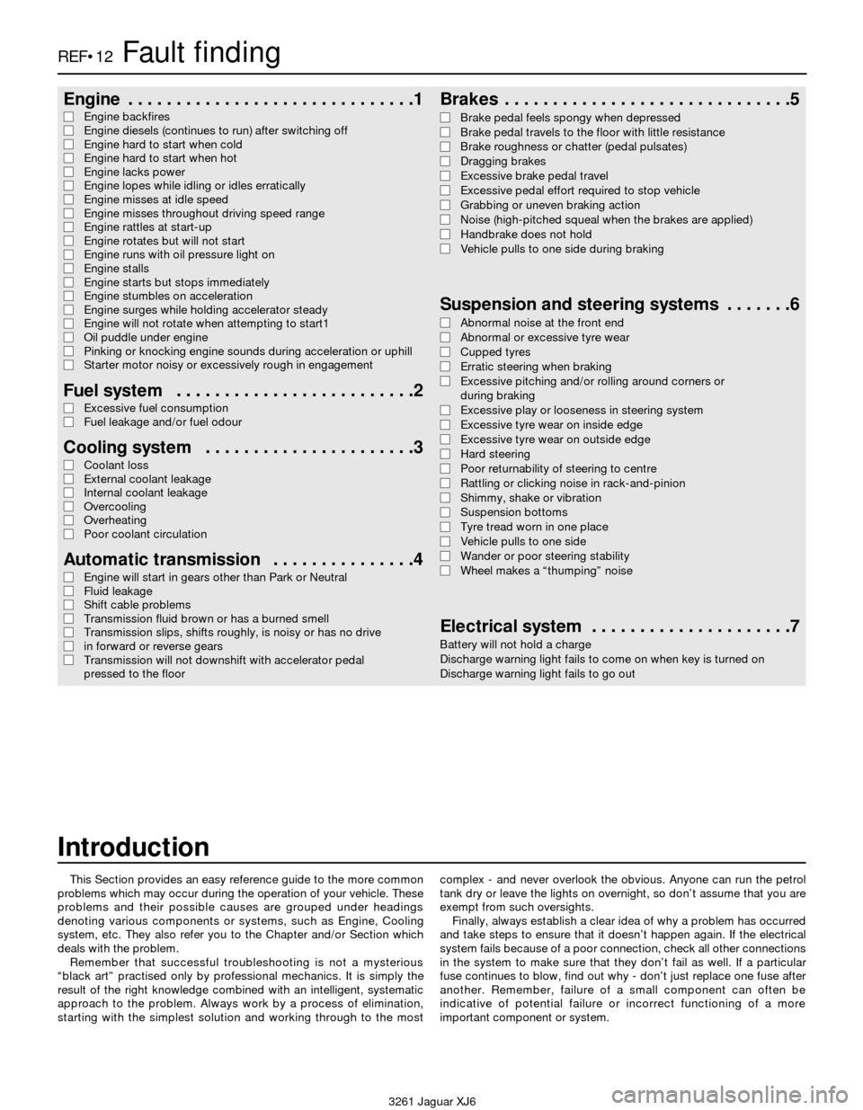
Suspension and steering systems . . . . . . .6
m
mAbnormal noise at the front end
m mAbnormal or excessive tyre wear
m mCupped tyres
m mErratic steering when braking
m mExcessive pitching and/or rolling around corners or
during braking
m mExcessive play or looseness in steering system
m mExcessive tyre wear on inside edge
m mExcessive tyre wear on outside edge
m mHard steering
m mPoor returnability of steering to centre
m mRattling or clicking noise in rack-and-pinion
m mShimmy, shake or vibration
m mSuspension bottoms
m mTyre tread worn in one place
m mVehicle pulls to one side
m mWander or poor steering stability
m mWheel makes a “thumping” noise
Electrical system . . . . . . . . . . . . . . . . . . . . .7
Battery will not hold a charge
Discharge warning light fails to come on when key is turned on
Discharge warning light fails to go out
Page 214 of 227
3261 Jaguar XJ6
Fault findingREF•13
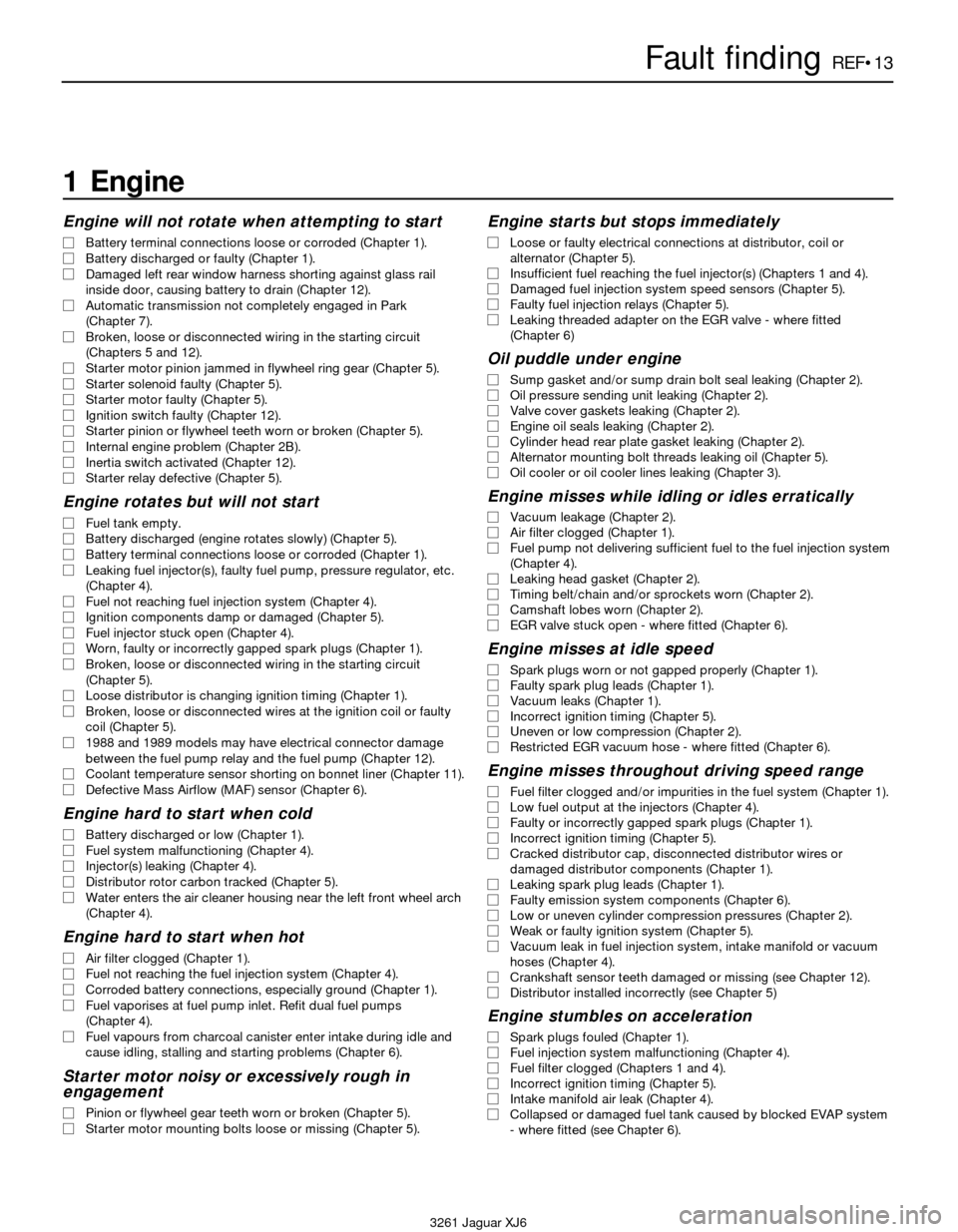
1 Engine
Engine will not rotate when attempting to start
m mBattery terminal connections loose or corroded (Chapter 1).
m mBattery discharged or faulty (Chapter 1).
m mDamaged left rear window harness shorting against glass rail
inside door, causing battery to drain (Chapter 12).
m mAutomatic transmission not completely engaged in Park
(Chapter 7).
m mBroken, loose or disconnected wiring in the starting circuit
(Chapters 5 and 12).
m mStarter motor pinion jammed in flywheel ring gear (Chapter 5).
m mStarter solenoid faulty (Chapter 5).
m mStarter motor faulty (Chapter 5).
m mIgnition switch faulty (Chapter 12).
m mStarter pinion or flywheel teeth worn or broken (Chapter 5).
m mInternal engine problem (Chapter 2B).
m mInertia switch activated (Chapter 12).
m mStarter relay defective (Chapter 5).
Engine rotates but will not start
m
mFuel tank empty.
m mBattery discharged (engine rotates slowly) (Chapter 5).
m mBattery terminal connections loose or corroded (Chapter 1).
m mLeaking fuel injector(s), faulty fuel pump, pressure regulator, etc.
(Chapter 4).
m mFuel not reaching fuel injection system (Chapter 4).
m mIgnition components damp or damaged (Chapter 5).
m mFuel injector stuck open (Chapter 4).
m mWorn, faulty or incorrectly gapped spark plugs (Chapter 1).
m mBroken, loose or disconnected wiring in the starting circuit
(Chapter 5).
m mLoose distributor is changing ignition timing (Chapter 1).
m mBroken, loose or disconnected wires at the ignition coil or faulty
coil (Chapter 5).
m m1988 and 1989 models may have electrical connector damage
between the fuel pump relay and the fuel pump (Chapter 12).
m mCoolant temperature sensor shorting on bonnet liner (Chapter 11).
m mDefective Mass Airflow (MAF) sensor (Chapter 6).
Engine hard to start when cold
m
mBattery discharged or low (Chapter 1).
m mFuel system malfunctioning (Chapter 4).
m mInjector(s) leaking (Chapter 4).
m mDistributor rotor carbon tracked (Chapter 5).
m mWater enters the air cleaner housing near the left front wheel arch
(Chapter 4).
Engine hard to start when hot
m mAir filter clogged (Chapter 1).
m mFuel not reaching the fuel injection system (Chapter 4).
m mCorroded battery connections, especially ground (Chapter 1).
m mFuel vaporises at fuel pump inlet. Refit dual fuel pumps
(Chapter 4).
m mFuel vapours from charcoal canister enter intake during idle and
cause idling, stalling and starting problems (Chapter 6).
Starter motor noisy or excessively rough in
engagement
m mPinion or flywheel gear teeth worn or broken (Chapter 5).
m mStarter motor mounting bolts loose or missing (Chapter 5).
Engine starts but stops immediately
m
mLoose or faulty electrical connections at distributor, coil or
alternator (Chapter 5).
m mInsufficient fuel reaching the fuel injector(s) (Chapters 1 and 4).
m mDamaged fuel injection system speed sensors (Chapter 5).
m mFaulty fuel injection relays (Chapter 5).
m mLeaking threaded adapter on the EGR valve - where fitted
(Chapter 6)
Oil puddle under engine
m mSump gasket and/or sump drain bolt seal leaking (Chapter 2).
m mOil pressure sending unit leaking (Chapter 2).
m mValve cover gaskets leaking (Chapter 2).
m mEngine oil seals leaking (Chapter 2).
m mCylinder head rear plate gasket leaking (Chapter 2).
m mAlternator mounting bolt threads leaking oil (Chapter 5).
m mOil cooler or oil cooler lines leaking (Chapter 3).
Engine misses while idling or idles erratically
m
mVacuum leakage (Chapter 2).
m mAir filter clogged (Chapter 1).
m mFuel pump not delivering sufficient fuel to the fuel injection system
(Chapter 4).
m mLeaking head gasket (Chapter 2).
m mTiming belt/chain and/or sprockets worn (Chapter 2).
m mCamshaft lobes worn (Chapter 2).
m mEGR valve stuck open - where fitted (Chapter 6).
Engine misses at idle speed
m
mSpark plugs worn or not gapped properly (Chapter 1).
m mFaulty spark plug leads (Chapter 1).
m mVacuum leaks (Chapter 1).
m mIncorrect ignition timing (Chapter 5).
m mUneven or low compression (Chapter 2).
m mRestricted EGR vacuum hose - where fitted (Chapter 6).
Engine misses throughout driving speed range
m
mFuel filter clogged and/or impurities in the fuel system (Chapter 1).
m mLow fuel output at the injectors (Chapter 4).
m mFaulty or incorrectly gapped spark plugs (Chapter 1).
m mIncorrect ignition timing (Chapter 5).
m mCracked distributor cap, disconnected distributor wires or
damaged distributor components (Chapter 1).
m mLeaking spark plug leads (Chapter 1).
m mFaulty emission system components (Chapter 6).
m mLow or uneven cylinder compression pressures (Chapter 2).
m mWeak or faulty ignition system (Chapter 5).
m mVacuum leak in fuel injection system, intake manifold or vacuum
hoses (Chapter 4).
m mCrankshaft sensor teeth damaged or missing (see Chapter 12).
m mDistributor installed incorrectly (see Chapter 5)
Engine stumbles on acceleration
m
mSpark plugs fouled (Chapter 1).
m mFuel injection system malfunctioning (Chapter 4).
m mFuel filter clogged (Chapters 1 and 4).
m mIncorrect ignition timing (Chapter 5).
m mIntake manifold air leak (Chapter 4).
m mCollapsed or damaged fuel tank caused by blocked EVAP system
- where fitted (see Chapter 6).
Page 217 of 227
3261 Jaguar XJ6
REF•16Fault finding
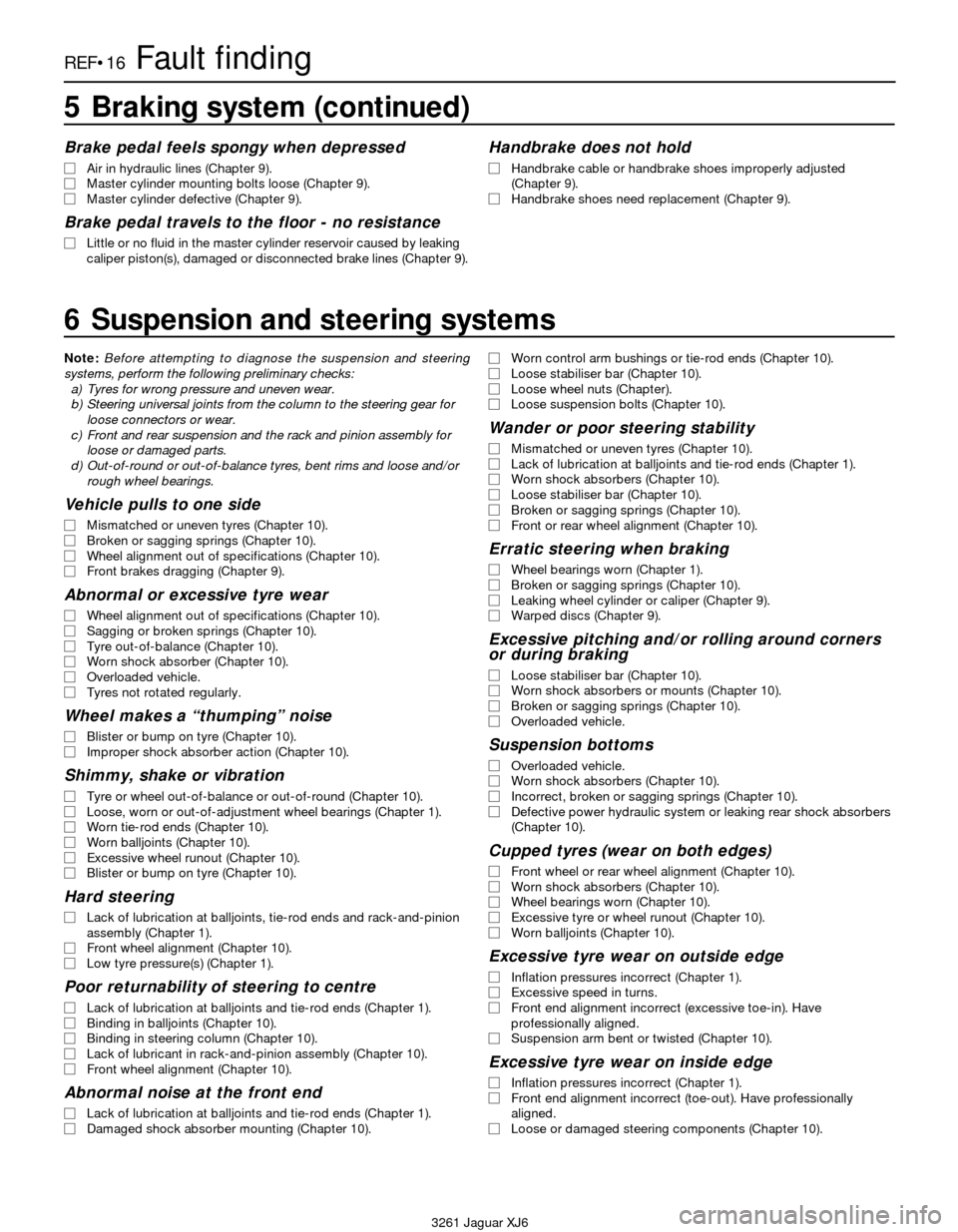
6 Suspension and steering systems
5 Braking system (continued)
Brake pedal feels spongy when depressed
m mAir in hydraulic lines (Chapter 9).
m mMaster cylinder mounting bolts loose (Chapter 9).
m mMaster cylinder defective (Chapter 9).
Brake pedal travels to the floor - no resistance
m
mLittle or no fluid in the master cylinder reservoir caused by leaking
caliper piston(s), damaged or disconnected brake lines (Chapter 9).
Handbrake does not hold
m mHandbrake cable or handbrake shoes improperly adjusted
(Chapter 9).
m mHandbrake shoes need replacement (Chapter 9).
Note:Before attempting to diagnose the suspension and steering
systems, perform the following preliminary checks:
a) Tyres for wrong pressure and uneven wear.
b) Steering universal joints from the column to the steering gear for
loose connectors or wear.
c) Front and rear suspension and the rack and pinion assembly for
loose or damaged parts.
d) Out-of-round or out-of-balance tyres, bent rims and loose and/or
rough wheel bearings.
Vehicle pulls to one side
m mMismatched or uneven tyres (Chapter 10).
m mBroken or sagging springs (Chapter 10).
m mWheel alignment out of specifications (Chapter 10).
m mFront brakes dragging (Chapter 9).
Abnormal or excessive tyre wear
m
mWheel alignment out of specifications (Chapter 10).
m mSagging or broken springs (Chapter 10).
m mTyre out-of-balance (Chapter 10).
m mWorn shock absorber (Chapter 10).
m mOverloaded vehicle.
m mTyres not rotated regularly.
Wheel makes a “thumping” noise
m
mBlister or bump on tyre (Chapter 10).
m mImproper shock absorber action (Chapter 10).
Shimmy, shake or vibration
m
mTyre or wheel out-of-balance or out-of-round (Chapter 10).
m mLoose, worn or out-of-adjustment wheel bearings (Chapter 1).
m mWorn tie-rod ends (Chapter 10).
m mWorn balljoints (Chapter 10).
m mExcessive wheel runout (Chapter 10).
m mBlister or bump on tyre (Chapter 10).
Hard steering
m
mLack of lubrication at balljoints, tie-rod ends and rack-and-pinion
assembly (Chapter 1).
m mFront wheel alignment (Chapter 10).
m mLow tyre pressure(s) (Chapter 1).
Poor returnability of steering to centre
m
mLack of lubrication at balljoints and tie-rod ends (Chapter 1).
m mBinding in balljoints (Chapter 10).
m mBinding in steering column (Chapter 10).
m mLack of lubricant in rack-and-pinion assembly (Chapter 10).
m mFront wheel alignment (Chapter 10).
Abnormal noise at the front end
m
mLack of lubrication at balljoints and tie-rod ends (Chapter 1).
m mDamaged shock absorber mounting (Chapter 10).m mWorn control arm bushings or tie-rod ends (Chapter 10).
m mLoose stabiliser bar (Chapter 10).
m mLoose wheel nuts (Chapter).
m mLoose suspension bolts (Chapter 10).
Wander or poor steering stability
m
mMismatched or uneven tyres (Chapter 10).
m mLack of lubrication at balljoints and tie-rod ends (Chapter 1).
m mWorn shock absorbers (Chapter 10).
m mLoose stabiliser bar (Chapter 10).
m mBroken or sagging springs (Chapter 10).
m mFront or rear wheel alignment (Chapter 10).
Erratic steering when braking
m
mWheel bearings worn (Chapter 1).
m mBroken or sagging springs (Chapter 10).
m mLeaking wheel cylinder or caliper (Chapter 9).
m mWarped discs (Chapter 9).
Excessive pitching and/or rolling around corners
or during braking
m mLoose stabiliser bar (Chapter 10).
m mWorn shock absorbers or mounts (Chapter 10).
m mBroken or sagging springs (Chapter 10).
m mOverloaded vehicle.
Suspension bottoms
m
mOverloaded vehicle.
m mWorn shock absorbers (Chapter 10).
m mIncorrect, broken or sagging springs (Chapter 10).
m mDefective power hydraulic system or leaking rear shock absorbers
(Chapter 10).
Cupped tyres (wear on both edges)
m mFront wheel or rear wheel alignment (Chapter 10).
m mWorn shock absorbers (Chapter 10).
m mWheel bearings worn (Chapter 10).
m mExcessive tyre or wheel runout (Chapter 10).
m mWorn balljoints (Chapter 10).
Excessive tyre wear on outside edge
m
mInflation pressures incorrect (Chapter 1).
m mExcessive speed in turns.
m mFront end alignment incorrect (excessive toe-in). Have
professionally aligned.
m mSuspension arm bent or twisted (Chapter 10).
Excessive tyre wear on inside edge
m
mInflation pressures incorrect (Chapter 1).
m mFront end alignment incorrect (toe-out). Have professionally
aligned.
m mLoose or damaged steering components (Chapter 10).
Page 218 of 227

3261 Jaguar XJ6
Fault findingREF•17
6 Suspension and steering systems (continued)
Tyre tread worn in one place
m mTyres out-of-balance.
m mDamaged or buckled wheel. Inspect and replace if necessary.
m mDefective tyre (Chapter 1).
Excessive play or looseness in steering system
m
mWheel bearing(s) worn (Chapter 10.m mTie-rod end loose or worn (Chapter 10).
m mSteering gear loose or worn (Chapter 10).
Rattling or clicking noise in rack-and-pinion
m
mInsufficient or improper power steering fluid in steering system
(Chapter 10).
m mSteering gear mounts loose (Chapter 10).
7 Electrical system
Battery will not hold a charge
m
mAlternator drivebelt defective or not adjusted properly (Chapter 1).
m mElectrolyte level low (Chapter 1).
m mBattery terminals loose or corroded (Chapter 1).
m mAlternator not charging properly (Chapter 5).
m mLoose, broken or faulty wiring in the charging circuit (Chapter 5).
m mShort in vehicle wiring (Chapters 5 and 12).
m mInternally defective battery (Chapters 1 and 5).
m mDamaged left rear window harness shorting against glass rail
inside door, causing battery to drain (Chapter 12).
Charge warning light fails to go out
m mFaulty alternator or charging circuit (Chapter 5).
m mAlternator drivebelt defective or out of adjustment (Chapter 1).
m mAlternator voltage regulator inoperative (Chapter 5).
Charge warning light fails to come on
when key is turned on
m mWarning light bulb defective (Chapter 12).
m mFault in the printed circuit, dash wiring or bulb holder (Chapter 12).
Page 221 of 227
3261 Jaguar XJ6
REF•20Glossary of technical terms
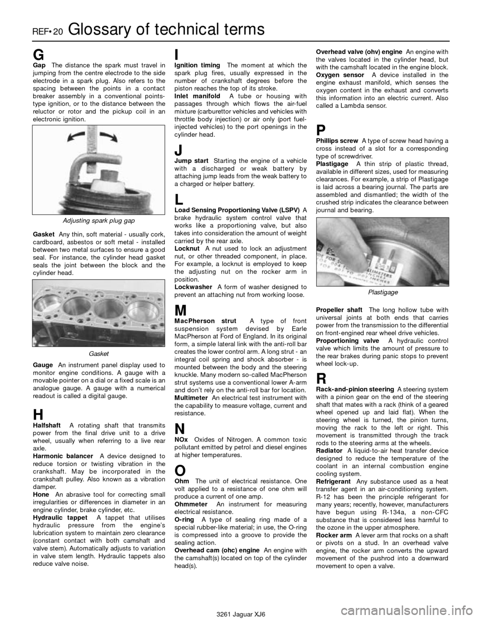
GGapThe distance the spark must travel in
jumping from the centre electrode to the side
electrode in a spark plug. Also refers to the
spacing between the points in a contact
breaker assembly in a conventional points-
type ignition, or to the distance between the
reluctor or rotor and the pickup coil in an
electronic ignition.
GasketAny thin, soft material - usually cork,
cardboard, asbestos or soft metal - installed
between two metal surfaces to ensure a good
seal. For instance, the cylinder head gasket
seals the joint between the block and the
cylinder head.
GaugeAn instrument panel display used to
monitor engine conditions. A gauge with a
movable pointer on a dial or a fixed scale is an
analogue gauge. A gauge with a numerical
readout is called a digital gauge.
HHalfshaftA rotating shaft that transmits
power from the final drive unit to a drive
wheel, usually when referring to a live rear
axle.
Harmonic balancerA device designed to
reduce torsion or twisting vibration in the
crankshaft. May be incorporated in the
crankshaft pulley. Also known as a vibration
damper.
HoneAn abrasive tool for correcting small
irregularities or differences in diameter in an
engine cylinder, brake cylinder, etc.
Hydraulic tappetA tappet that utilises
hydraulic pressure from the engine’s
lubrication system to maintain zero clearance
(constant contact with both camshaft and
valve stem). Automatically adjusts to variation
in valve stem length. Hydraulic tappets also
reduce valve noise.
IIgnition timingThe moment at which the
spark plug fires, usually expressed in the
number of crankshaft degrees before the
piston reaches the top of its stroke.
Inlet manifoldA tube or housing with
passages through which flows the air-fuel
mixture (carburettor vehicles and vehicles with
throttle body injection) or air only (port fuel-
injected vehicles) to the port openings in the
cylinder head.
JJump startStarting the engine of a vehicle
with a discharged or weak battery by
attaching jump leads from the weak battery to
a charged or helper battery.
LLoad Sensing Proportioning Valve (LSPV)A
brake hydraulic system control valve that
works like a proportioning valve, but also
takes into consideration the amount of weight
carried by the rear axle.
LocknutA nut used to lock an adjustment
nut, or other threaded component, in place.
For example, a locknut is employed to keep
the adjusting nut on the rocker arm in
position.
LockwasherA form of washer designed to
prevent an attaching nut from working loose.
MMacPherson strutA type of front
suspension system devised by Earle
MacPherson at Ford of England. In its original
form, a simple lateral link with the anti-roll bar
creates the lower control arm. A long strut - an
integral coil spring and shock absorber - is
mounted between the body and the steering
knuckle. Many modern so-called MacPherson
strut systems use a conventional lower A-arm
and don’t rely on the anti-roll bar for location.
MultimeterAn electrical test instrument with
the capability to measure voltage, current and
resistance.
NNOxOxides of Nitrogen. A common toxic
pollutant emitted by petrol and diesel engines
at higher temperatures.
OOhmThe unit of electrical resistance. One
volt applied to a resistance of one ohm will
produce a current of one amp.
OhmmeterAn instrument for measuring
electrical resistance.
O-ringA type of sealing ring made of a
special rubber-like material; in use, the O-ring
is compressed into a groove to provide the
sealing action.
Overhead cam (ohc) engineAn engine with
the camshaft(s) located on top of the cylinder
head(s).Overhead valve (ohv) engineAn engine with
the valves located in the cylinder head, but
with the camshaft located in the engine block.
Oxygen sensorA device installed in the
engine exhaust manifold, which senses the
oxygen content in the exhaust and converts
this information into an electric current. Also
called a Lambda sensor.
PPhillips screwA type of screw head having a
cross instead of a slot for a corresponding
type of screwdriver.
PlastigageA thin strip of plastic thread,
available in different sizes, used for measuring
clearances. For example, a strip of Plastigage
is laid across a bearing journal. The parts are
assembled and dismantled; the width of the
crushed strip indicates the clearance between
journal and bearing.
Propeller shaftThe long hollow tube with
universal joints at both ends that carries
power from the transmission to the differential
on front-engined rear wheel drive vehicles.
Proportioning valveA hydraulic control
valve which limits the amount of pressure to
the rear brakes during panic stops to prevent
wheel lock-up.
RRack-and-pinion steeringA steering system
with a pinion gear on the end of the steering
shaft that mates with a rack (think of a geared
wheel opened up and laid flat). When the
steering wheel is turned, the pinion turns,
moving the rack to the left or right. This
movement is transmitted through the track
rods to the steering arms at the wheels.
RadiatorA liquid-to-air heat transfer device
designed to reduce the temperature of the
coolant in an internal combustion engine
cooling system.
RefrigerantAny substance used as a heat
transfer agent in an air-conditioning system.
R-12 has been the principle refrigerant for
many years; recently, however, manufacturers
have begun using R-134a, a non-CFC
substance that is considered less harmful to
the ozone in the upper atmosphere.
Rocker armA lever arm that rocks on a shaft
or pivots on a stud. In an overhead valve
engine, the rocker arm converts the upward
movement of the pushrod into a downward
movement to open a valve.
Adjusting spark plug gap
Plastigage
Gasket