fluids JAGUAR XJ6 1997 2.G Workshop Manual
[x] Cancel search | Manufacturer: JAGUAR, Model Year: 1997, Model line: XJ6, Model: JAGUAR XJ6 1997 2.GPages: 227, PDF Size: 7.2 MB
Page 2 of 227

3261 Jaguar XJ6
LIVING WITH YOUR JAGUAR XJ6
IntroductionPage 0•4
Notes for UK readersPage 0•4
Safety first!Page 0•5
Roadside repairs
IntroductionPage 0•6
If your car won’t startPage 0•6
Jump startingPage 0•7
Wheel changingPage 0•8
Identifying leaksPage 0•9
TowingPage 0•9
Weekly checks
IntroductionPage 0•10
Underbonnet check points Page 0•10
Engine oil levelPage 0•11
Coolant levelPage 0•11
Brake fluid levelPage 0•12
Screen washer fluid level Page 0•12
Power steering fluid level Page 0•13
Wiper bladesPage 0•13
Tyre condition and pressure Page 0•14
BatteryPage 0•15
Bulbs and fusesPage 0•15
Lubricants, fluids and tyre pressuresPage 0•16
MAINTENANCE
Routine maintenance and servicingPage 1•1
Servicing specificationsPage 1•2
Maintenance schedulePage 1•3
Maintenance procedures Page 1•6
Contents
Page 9 of 227
3261 Jaguar XJ6
Roadside repairs0•9
When all else fails, you may find yourself
having to get a tow home – or of course you
may be helping somebody else. Long-distance
recovery should only be done by a garage or
breakdown service. For shorter distances, DIY
towing using another car is easy enough, but
observe the following points:
MUse a proper tow-rope – they are not
expensive. The vehicle being towed must
display an ‘ON TOW’ sign in its rear window.
MAlways turn the ignition key to the ‘on’
position when the vehicle is being towed, so
that the steering lock is released, and that the
direction indicator and brake lights will work.
MOnly attach the tow-rope to the towing
eyes provided. On some models with energy-
absorbing bumpers there are no front towing
eyes; on these vehicles the tow-rope shouldbe attached around the rear arm of the lower
control arm so that the rope passes on the
inside of the coil spring.
MBefore being towed, release the handbrake
and select neutral on the transmission.
MNote that greater-than-usual pedal
pressure will be required to operate the
brakes, since the vacuum servo unit is only
operational with the engine running.
MOn models with power steering, greater-
than-usual steering effort will also be required.
MThe driver of the car being towed must
keep the tow-rope taut at all times to avoid
snatching.
MMake sure that both drivers know the route
before setting off.
MOnly drive at moderate speeds and keep
the distance towed to a minimum. Drivesmoothly and allow plenty of time for slowing
down at junctions.
MOn models with automatic transmission,
special precautions apply. If in doubt, do not
tow, or transmission damage may result.
Caution: On models with automatic
transmission, if the vehicle is to be towed
with its rear wheels on the ground, and
extra 1.7 litres of fluid should be added to
the transmission, prior to towing (this extra
fluid must be drained before driving the
vehicle). Even with the extra fluid added to
the transmission, do not tow the vehicle at
speeds in excess of 30 mph (50 kmh) or for
a distance of greater than 15 miles (25 km).
If towing speed/distance are to exceed
these limits, then the vehicle must be
towed with its rear wheels off the ground.
Towing
Puddles on the garage floor or drive, or
obvious wetness under the bonnet or
underneath the car, suggest a leak that needs
investigating. It can sometimes be difficult to
decide where the leak is coming from,
especially if the engine bay is very dirty
already. Leaking oil or fluid can also be blown
rearwards by the passage of air under the car,
giving a false impression of where the
problem lies.Warning: Most automotive oils
and fluids are poisonous. Wash
them off skin, and change out of
contaminated clothing, without
delay.The smell of a fluid leaking
from the car may provide a
clue to what’s leaking. Some
fluids are distinctively
coloured. It may help to clean the car and
to park it over some clean paper as an
aid to locating the source of the leak.
Remember that some leaks may only
occur while the engine is running.
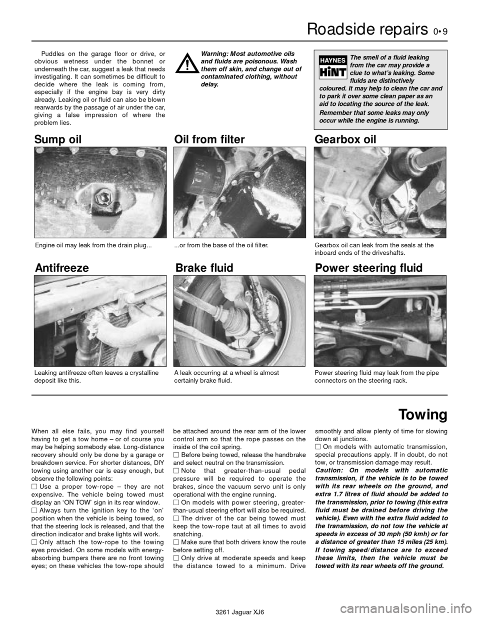
Sump oil Gearbox oil
Brake fluid
Power steering fluid
Oil from filter
Antifreeze
Engine oil may leak from the drain plug......or from the base of the oil filter.
Leaking antifreeze often leaves a crystalline
deposit like this.Gearbox oil can leak from the seals at the
inboard ends of the driveshafts.
A leak occurring at a wheel is almost
certainly brake fluid.Power steering fluid may leak from the pipe
connectors on the steering rack.
Page 11 of 227
3261 Jaguar XJ6
Weekly checks0•11
Engine oil level
Before you start
4Make sure that your car is on level ground.
4Check the oil level before the car is driven,
or at least 5 minutes after the engine has been
switched off.
The correct oilModern engines place great demands on their
oil. It is very important that the correct oil for
your car is used (See “Lubricants, fluids and
tyre pressures”).
Car care
l If you have to add oil frequently, you should
check whether you have any oil leaks. Place
some clean paper under the car overnight,
and check for stains in the morning. If there
are no leaks, the engine may be burning oil
(see “Fault finding”).
lAlways maintain the level between the
upper and lower dipstick marks (see photo 3).
If the level is too low severe engine damage
may occur. Oil seal failure may result if the
engine is overfilled by adding too much oil.
If the oil level is checked
immediately after driving the
vehicle, some of the oil will
remain in the upper engine
components, resulting in an inaccurate
reading on the dipstick!
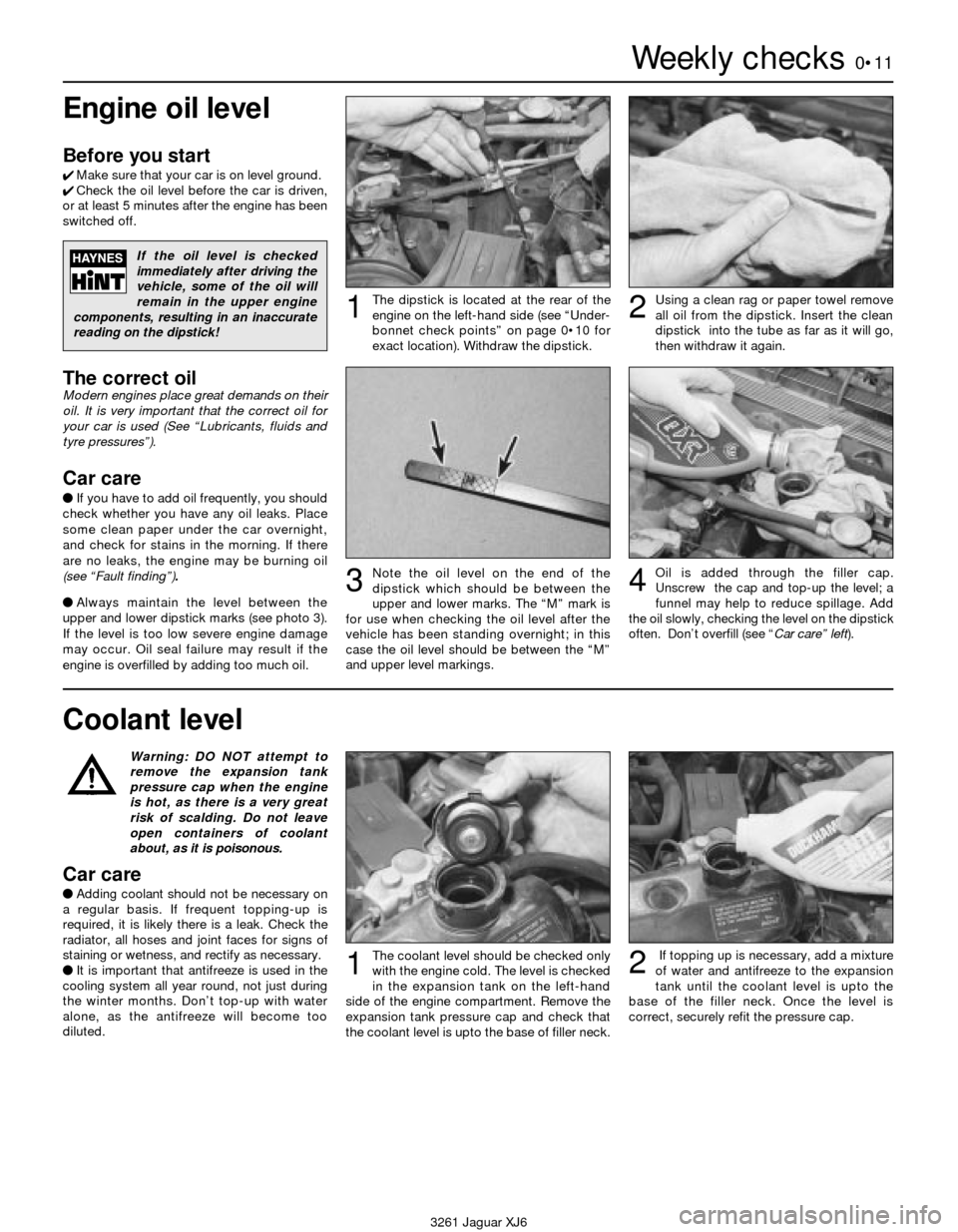
The dipstick is located at the rear of the
engine on the left-hand side (see “Under-
bonnet check points” on page 0•10 for
exact location). Withdraw the dipstick.Using a clean rag or paper towel remove
all oil from the dipstick. Insert the clean
dipstick into the tube as far as it will go,
then withdraw it again.
Note the oil level on the end of the
dipstick which should be between the
upper and lower marks. The “M” mark is
for use when checking the oil level after the
vehicle has been standing overnight; in this
case the oil level should be between the “M”
and upper level markings.Oil is added through the filler cap.
Unscrew the cap and top-up the level; a
funnel may help to reduce spillage. Add
the oil slowly, checking the level on the dipstick
often. Don’t overfill (see “Car care” left).
12
34
Warning: DO NOT attempt to
remove the expansion tank
pressure cap when the engine
is hot, as there is a very great
risk of scalding. Do not leave
open containers of coolant
about, as it is poisonous.
Car care
lAdding coolant should not be necessary on
a regular basis. If frequent topping-up is
required, it is likely there is a leak. Check the
radiator, all hoses and joint faces for signs of
staining or wetness, and rectify as necessary.
lIt is important that antifreeze is used in the
cooling system all year round, not just during
the winter months. Don’t top-up with water
alone, as the antifreeze will become too
diluted.
Coolant level
The coolant level should be checked only
with the engine cold. The level is checked
in the expansion tank on the left-hand
side of the engine compartment. Remove the
expansion tank pressure cap and check that
the coolant level is upto the base of filler neck.If topping up is necessary, add a mixture
of water and antifreeze to the expansion
tank until the coolant level is upto the
base of the filler neck. Once the level is
correct, securely refit the pressure cap.12
Page 13 of 227
3261 Jaguar XJ6
Weekly checks0•13
Power steering
fluid level
Before you start:
4Park the vehicle on level ground.
4Set the steering wheel straight-ahead.
4The engine should be turned off.
Safety first!
lThe need for frequent topping-up indicates
a leak, which should be investigated
immediately.
For the check to be
accurate, the steering must
not be turned once the
engine has been stopped.
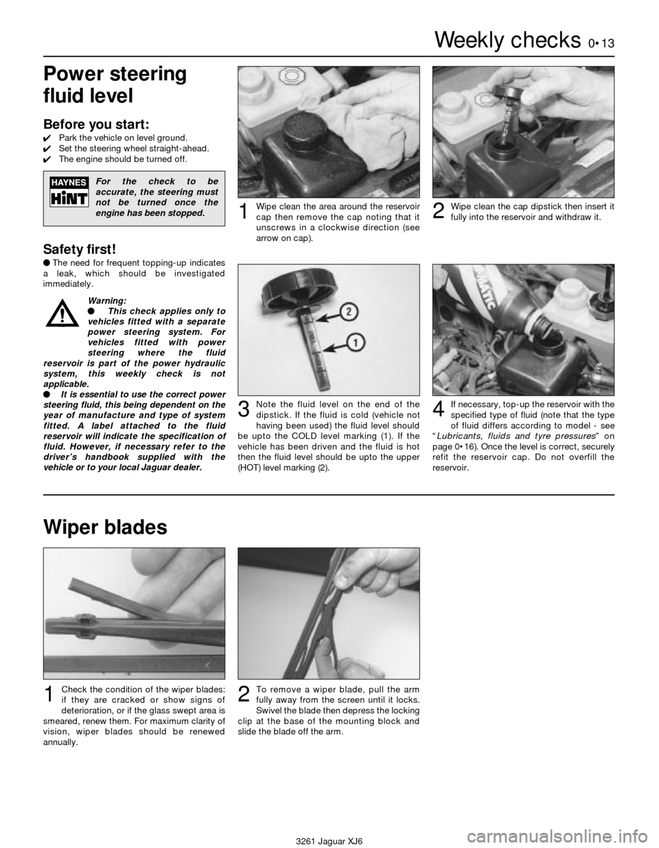
Wipe clean the area around the reservoir
cap then remove the cap noting that it
unscrews in a clockwise direction (see
arrow on cap).1Wipe clean the cap dipstick then insert it
fully into the reservoir and withdraw it.2
Note the fluid level on the end of the
dipstick. If the fluid is cold (vehicle not
having been used) the fluid level should
be upto the COLD level marking (1). If the
vehicle has been driven and the fluid is hot
then the fluid level should be upto the upper
(HOT) level marking (2).3If necessary, top-up the reservoir with the
specified type of fluid (note that the type
of fluid differs according to model - see
“Lubricants, fluids and tyre pressures” on
page 0•16). Once the level is correct, securely
refit the reservoir cap. Do not overfill the
reservoir.4
Wiper blades
Check the condition of the wiper blades:
if they are cracked or show signs of
deterioration, or if the glass swept area is
smeared, renew them. For maximum clarity of
vision, wiper blades should be renewed
annually.1To remove a wiper blade, pull the arm
fully away from the screen until it locks.
Swivel the blade then depress the locking
clip at the base of the mounting block and
slide the blade off the arm.2
Warning:
l This check applies only to
vehicles fitted with a separate
power steering system. For
vehicles fitted with power
steering where the fluid
reservoir is part of the power hydraulic
system, this weekly check is not
applicable.
l It is essential to use the correct power
steering fluid, this being dependent on the
year of manufacture and type of system
fitted. A label attached to the fluid
reservoir will indicate the specification of
fluid. However, if necessary refer to the
driver’s handbook supplied with the
vehicle or to your local Jaguar dealer.
Page 16 of 227
0•16Lubricants, fluids and tyre pressures
3261 Jaguar XJ6
Lubricants and fluids
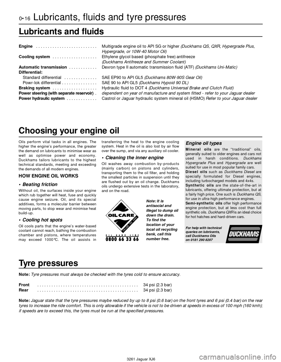
Engine . . . . . . . . . . . . . . . . . . . . . . . . . . Multigrade engine oil to API SG or higher (Duckhams QS, QXR, Hypergrade Plus,
Hypergrade, or 10W-40 Motor Oil)
Cooling system . . . . . . . . . . . . . . . . . . . Ethylene glycol based (phosphate free) antifreeze
(Duckhams Antifreeze and Summer Coolant)
Automatic transmission . . . . . . . . . . . . Dexron type II automatic transmission fluid (ATF) (Duckhams Uni-Matic)
Differential:
Standard differential . . . . . . . . . . . . . . SAE EP90 to API GL5 (Duckhams 80W-90S Gear Oil)
Powr-lok differential . . . . . . . . . . . . . . . SAE 90 to API GL5 (Duckhams Hypoid 90 DL)
Braking system . . . . . . . . . . . . . . . . . . . Hydraulic fluid to DOT 4 (Duckhams Universal Brake and Clutch Fluid)
Power steering (with separate reservoir) .dependent on year of manufacture and system fitted - refer to your Jaguar dealer
Power hydraulic system . . . . . . . . . . . . . Castrol or Jaguar hydraulic system mineral oil (HSMO) Refer to your Jaguar dealer
Tyre pressures
Note:Tyre pressures must always be checked with the tyres cold to ensure accuracy.
Front . . . . . . . . . . . . . . . . . . . . . . . . . . . . . . . . . . . . . . . . . . . 34 psi (2.3 bar)
Rear . . . . . . . . . . . . . . . . . . . . . . . . . . . . . . . . . . . . . . . . . . . 34 psi (2.3 bar)
Note:Jaguar state that the tyre pressures maybe reduced by up to 8 psi (0.6 bar) on the front tyres and 6 psi (0.4 bar) on the rear
tyres to increase the ride comfort. This is only allowable if the vehicle is not to be driven at speeds in excess of 100 mph (160 kmh);
if speeds are to exceed this, the tyres must be run at the specified pressures.
Oils perform vital tasks in all engines. The
higher the engine’s performance, the greater
the demand on lubricants to minimise wear as
well as optimise power and economy.
Duckhams tailors lubricants to the highest
technical standards, meeting and exceeding
the demands of all modern engines.
HOW ENGINE OIL WORKS
• Beating friction
Without oil, the surfaces inside your engine
which rub together will heat, fuse and quickly
cause engine seizure. Oil, and its special
additives, forms a molecular barrier between
moving parts, to stop wear and minimise heat
build-up.
• Cooling hot spots
Oil cools parts that the engine’s water-based
coolant cannot reach, bathing the combustion
chamber and pistons, where temperatures
may exceed 1000°C. The oil assists intransferring the heat to the engine cooling
system. Heat in the oil is also lost by air flow
over the sump, and via any auxiliary oil cooler.
• Cleaning the inner engine
Oil washes away combustion by-products
(mainly carbon) on pistons and cylinders,
transporting them to the oil filter, and holding
the smallest particles in suspension until they
are flushed out by an oil change. Duckhams
oils undergo extensive tests in the laboratory,
and on the road.
Engine oil types
Mineral oilsare the “traditional” oils,
generally suited to older engines and cars not
used in harsh conditions. Duckhams
Hypergrade Plus and Hypergradeare well
suited for use in most popular family cars.
Diesel oilssuch as Duckhams Dieselare
specially formulated for Diesel engines,
including turbocharged models and 4x4s.
Synthetic oilsare the state-of-the-art in
lubricants, offering ultimate protection, but at
a fairly high price. One such is Duckhams QS,
for use in ultra-high performance engines.
Semi-synthetic oilsoffer high performance
engine protection, but at less cost than full
synthetic oils. Duckhams QXRis an ideal choice
for hot hatches and hard-driven cars.
For help with technical
queries on lubricants,
call Duckhams Oils
on 0181 290 8207
Choosing your engine oil
Note: It is
antisocial and
illegal to dump oil
down the drain.
To find the
location of your
local oil recycling
bank, call this
number free.
Page 18 of 227
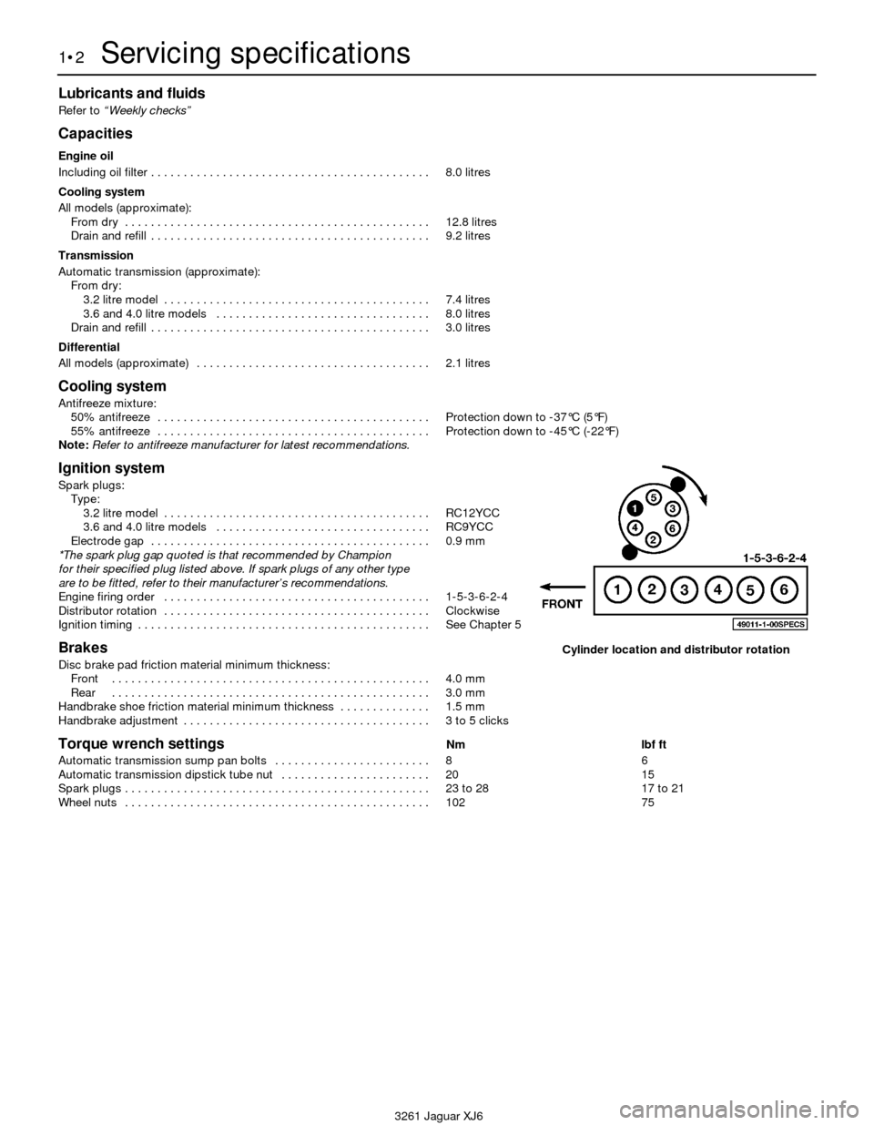
Lubricants and fluids
Refer to “Weekly checks”
Capacities
Engine oil
Including oil filter . . . . . . . . . . . . . . . . . . . . . . . . . . . . . . . . . . . . . . . . . . . 8.0 litres
Cooling system
All models (approximate):
From dry . . . . . . . . . . . . . . . . . . . . . . . . . . . . . . . . . . . . . . . . . . . . . . . 12.8 litres
Drain and refill . . . . . . . . . . . . . . . . . . . . . . . . . . . . . . . . . . . . . . . . . . . 9.2 litres
Transmission
Automatic transmission (approximate):
From dry:
3.2 litre model . . . . . . . . . . . . . . . . . . . . . . . . . . . . . . . . . . . . . . . . . 7.4 litres
3.6 and 4.0 litre models . . . . . . . . . . . . . . . . . . . . . . . . . . . . . . . . . 8.0 litres
Drain and refill . . . . . . . . . . . . . . . . . . . . . . . . . . . . . . . . . . . . . . . . . . . 3.0 litres
Differential
All models (approximate) . . . . . . . . . . . . . . . . . . . . . . . . . . . . . . . . . . . . 2.1 litres
Cooling system
Antifreeze mixture:
50% antifreeze . . . . . . . . . . . . . . . . . . . . . . . . . . . . . . . . . . . . . . . . . . Protection down to -37°C (5°F)
55% antifreeze . . . . . . . . . . . . . . . . . . . . . . . . . . . . . . . . . . . . . . . . . . Protection down to -45°C (-22°F)
Note:Refer to antifreeze manufacturer for latest recommendations.
Ignition system
Spark plugs:
Type:
3.2 litre model . . . . . . . . . . . . . . . . . . . . . . . . . . . . . . . . . . . . . . . . . RC12YCC
3.6 and 4.0 litre models . . . . . . . . . . . . . . . . . . . . . . . . . . . . . . . . . RC9YCC
Electrode gap . . . . . . . . . . . . . . . . . . . . . . . . . . . . . . . . . . . . . . . . . . . 0.9 mm
*The spark plug gap quoted is that recommended by Champion
for their specified plug listed above. If spark plugs of any other type
are to be fitted, refer to their manufacturer’s recommendations.
Engine firing order . . . . . . . . . . . . . . . . . . . . . . . . . . . . . . . . . . . . . . . . . 1-5-3-6-2-4
Distributor rotation . . . . . . . . . . . . . . . . . . . . . . . . . . . . . . . . . . . . . . . . . Clockwise
Ignition timing . . . . . . . . . . . . . . . . . . . . . . . . . . . . . . . . . . . . . . . . . . . . . See Chapter 5
Brakes
Disc brake pad friction material minimum thickness:
Front . . . . . . . . . . . . . . . . . . . . . . . . . . . . . . . . . . . . . . . . . . . . . . . . . 4.0 mm
Rear . . . . . . . . . . . . . . . . . . . . . . . . . . . . . . . . . . . . . . . . . . . . . . . . . 3.0 mm
Handbrake shoe friction material minimum thickness . . . . . . . . . . . . . . 1.5 mm
Handbrake adjustment . . . . . . . . . . . . . . . . . . . . . . . . . . . . . . . . . . . . . . 3 to 5 clicks
Torque wrench settingsNm lbf ft
Automatic transmission sump pan bolts . . . . . . . . . . . . . . . . . . . . . . . . 8 6
Automatic transmission dipstick tube nut . . . . . . . . . . . . . . . . . . . . . . . 20 15
Spark plugs . . . . . . . . . . . . . . . . . . . . . . . . . . . . . . . . . . . . . . . . . . . . . . . 23 to 28 17 to 21
Wheel nuts . . . . . . . . . . . . . . . . . . . . . . . . . . . . . . . . . . . . . . . . . . . . . . . 102 75
1•2Servicing specifications
3261 Jaguar XJ6
Cylinder location and distributor rotation
Page 22 of 227
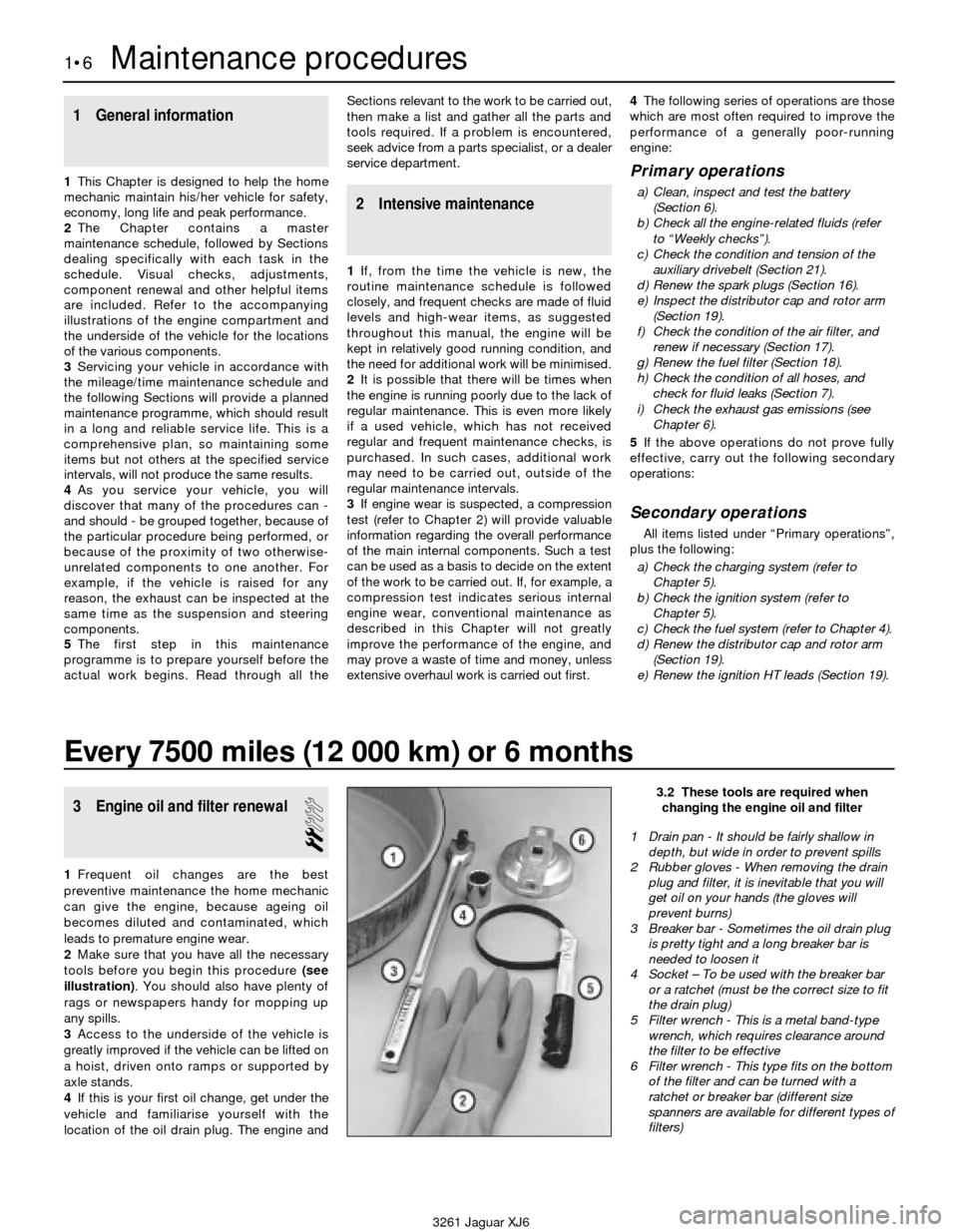
1 General information
1This Chapter is designed to help the home
mechanic maintain his/her vehicle for safety,
economy, long life and peak performance.
2The Chapter contains a master
maintenance schedule, followed by Sections
dealing specifically with each task in the
schedule. Visual checks, adjustments,
component renewal and other helpful items
are included. Refer to the accompanying
illustrations of the engine compartment and
the underside of the vehicle for the locations
of the various components.
3Servicing your vehicle in accordance with
the mileage/time maintenance schedule and
the following Sections will provide a planned
maintenance programme, which should result
in a long and reliable service life. This is a
comprehensive plan, so maintaining some
items but not others at the specified service
intervals, will not produce the same results.
4As you service your vehicle, you will
discover that many of the procedures can -
and should - be grouped together, because of
the particular procedure being performed, or
because of the proximity of two otherwise-
unrelated components to one another. For
example, if the vehicle is raised for any
reason, the exhaust can be inspected at the
same time as the suspension and steering
components.
5The first step in this maintenance
programme is to prepare yourself before the
actual work begins. Read through all theSections relevant to the work to be carried out,
then make a list and gather all the parts and
tools required. If a problem is encountered,
seek advice from a parts specialist, or a dealer
service department.
2 Intensive maintenance
1If, from the time the vehicle is new, the
routine maintenance schedule is followed
closely, and frequent checks are made of fluid
levels and high-wear items, as suggested
throughout this manual, the engine will be
kept in relatively good running condition, and
the need for additional work will be minimised.
2It is possible that there will be times when
the engine is running poorly due to the lack of
regular maintenance. This is even more likely
if a used vehicle, which has not received
regular and frequent maintenance checks, is
purchased. In such cases, additional work
may need to be carried out, outside of the
regular maintenance intervals.
3If engine wear is suspected, a compression
test (refer to Chapter 2) will provide valuable
information regarding the overall performance
of the main internal components. Such a test
can be used as a basis to decide on the extent
of the work to be carried out. If, for example, a
compression test indicates serious internal
engine wear, conventional maintenance as
described in this Chapter will not greatly
improve the performance of the engine, and
may prove a waste of time and money, unless
extensive overhaul work is carried out first.4The following series of operations are those
which are most often required to improve the
performance of a generally poor-running
engine:
Primary operations
a) Clean, inspect and test the battery
(Section 6).
b) Check all the engine-related fluids (refer
to “Weekly checks”).
c) Check the condition and tension of the
auxiliary drivebelt (Section 21).
d) Renew the spark plugs (Section 16).
e) Inspect the distributor cap and rotor arm
(Section 19).
f) Check the condition of the air filter, and
renew if necessary (Section 17).
g) Renew the fuel filter (Section 18).
h) Check the condition of all hoses, and
check for fluid leaks (Section 7).
i) Check the exhaust gas emissions (see
Chapter 6).
5If the above operations do not prove fully
effective, carry out the following secondary
operations:
Secondary operations
All items listed under “Primary operations”,
plus the following:
a) Check the charging system (refer to
Chapter 5).
b) Check the ignition system (refer to
Chapter 5).
c) Check the fuel system (refer to Chapter 4).
d) Renew the distributor cap and rotor arm
(Section 19).
e) Renew the ignition HT leads (Section 19).
1•6Maintenance procedures
3261 Jaguar XJ6
Every 7500 miles (12 000 km) or 6 months
3 Engine oil and filter renewal
2
1Frequent oil changes are the best
preventive maintenance the home mechanic
can give the engine, because ageing oil
becomes diluted and contaminated, which
leads to premature engine wear.
2Make sure that you have all the necessary
tools before you begin this procedure (see
illustration). You should also have plenty of
rags or newspapers handy for mopping up
any spills.
3Access to the underside of the vehicle is
greatly improved if the vehicle can be lifted on
a hoist, driven onto ramps or supported by
axle stands.
4If this is your first oil change, get under the
vehicle and familiarise yourself with the
location of the oil drain plug. The engine and
3.2 These tools are required when
changing the engine oil and filter
1 Drain pan - It should be fairly shallow in
depth, but wide in order to prevent spills
2 Rubber gloves - When removing the drain
plug and filter, it is inevitable that you will
get oil on your hands (the gloves will
prevent burns)
3 Breaker bar - Sometimes the oil drain plug
is pretty tight and a long breaker bar is
needed to loosen it
4 Socket – To be used with the breaker bar
or a ratchet (must be the correct size to fit
the drain plug)
5 Filter wrench - This is a metal band-type
wrench, which requires clearance around
the filter to be effective
6 Filter wrench - This type fits on the bottom
of the filter and can be turned with a
ratchet or breaker bar (different size
spanners are available for different types of
filters)
Page 60 of 227
11Disconnect the throttle linkage,
transmission linkage (and dipstick tube) and
speed control cable, if equipped, from the
engine (see Chapters 4 and 7).
12Refer to Part A of this Chapter and
remove the intake and exhaust manifolds.
13Unbolt the power steering pump (see
Chapter 10). Tie the pump aside without
disconnecting the hoses. Refer to Part A for
removal of the hydraulic pump (if equipped)
from the timing chain cover.
14On air-conditioned models, unbolt the
compressor and set it aside. Do not
disconnect the refrigerant hoses. Note:Wire
the compressor out of the way with a coat
hanger, don’t let the compressor hang on the
hoses.
15Refer to Part A of this Chapter and
remove the drivebelts, water pump pulley and
crankshaft pulley.
16Attach a lifting sling to the engine.
Position a hoist and connect the sling to it.
Take up the slack until there is slight tension
on the hoist.
17With a trolley jack and piece of wood
supporting the bottom of the transmission
sump, refer to Chapter 8 and remove the
driveshaft and rear transmission mount.
Warning: Do not place any part
of your body under the
engine/transmission when it’s
supported only by a hoist or
other lifting device.
18With the hoist taking the weight of the
engine, unbolt the engine mounts (see Part A
of this Chapter).
19Recheck to be sure nothing is still
connecting the engine or transmission to the
vehicle. Disconnect and label anything still
remaining.
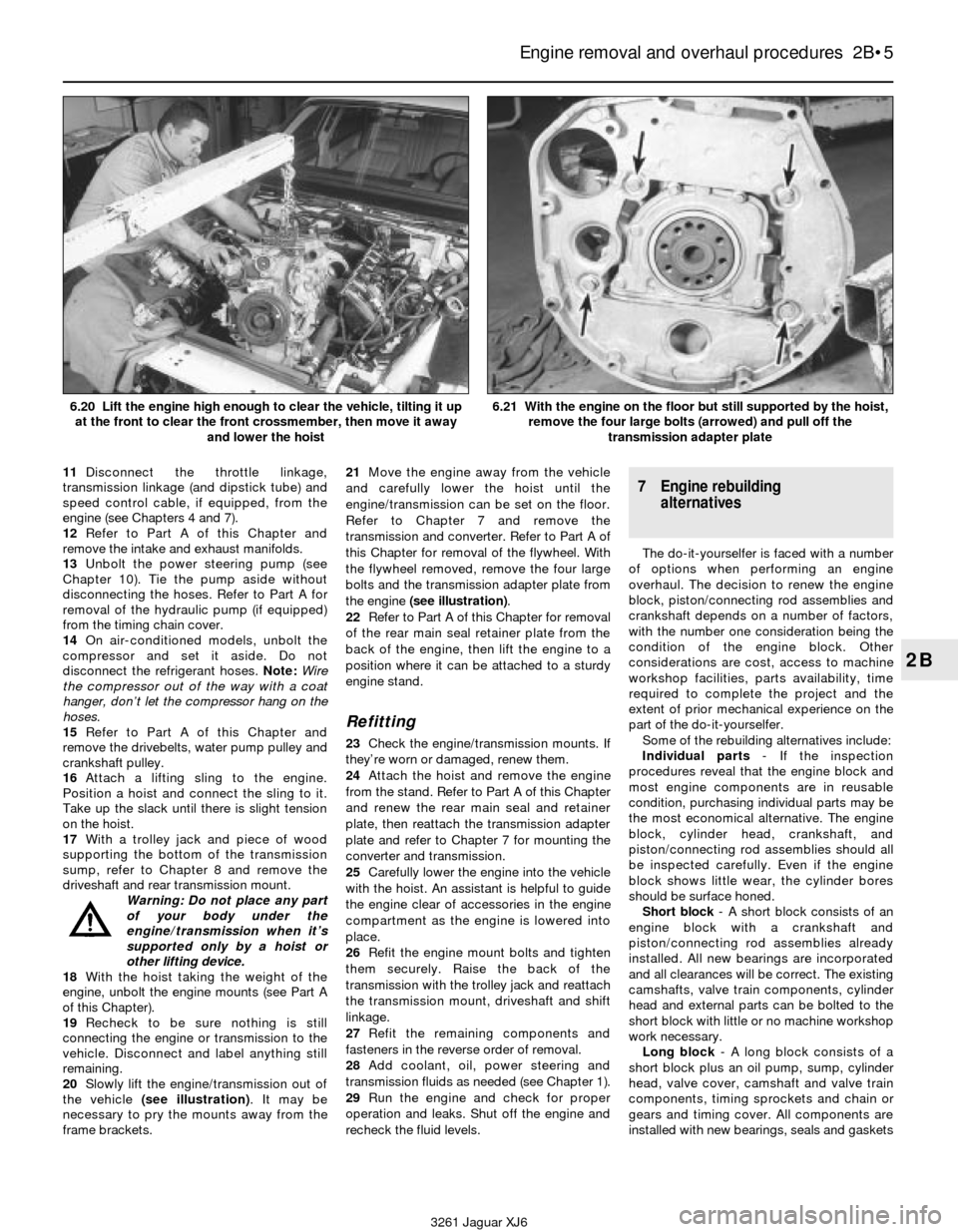
20Slowly lift the engine/transmission out of
the vehicle (see illustration). It may be
necessary to pry the mounts away from the
frame brackets.21Move the engine away from the vehicle
and carefully lower the hoist until the
engine/transmission can be set on the floor.
Refer to Chapter 7 and remove the
transmission and converter. Refer to Part A of
this Chapter for removal of the flywheel. With
the flywheel removed, remove the four large
bolts and the transmission adapter plate from
the engine (see illustration).
22Refer to Part A of this Chapter for removal
of the rear main seal retainer plate from the
back of the engine, then lift the engine to a
position where it can be attached to a sturdy
engine stand.
Refitting
23Check the engine/transmission mounts. If
they’re worn or damaged, renew them.
24Attach the hoist and remove the engine
from the stand. Refer to Part A of this Chapter
and renew the rear main seal and retainer
plate, then reattach the transmission adapter
plate and refer to Chapter 7 for mounting the
converter and transmission.
25Carefully lower the engine into the vehicle
with the hoist. An assistant is helpful to guide
the engine clear of accessories in the engine
compartment as the engine is lowered into
place.
26Refit the engine mount bolts and tighten
them securely. Raise the back of the
transmission with the trolley jack and reattach
the transmission mount, driveshaft and shift
linkage.
27Refit the remaining components and
fasteners in the reverse order of removal.
28Add coolant, oil, power steering and
transmission fluids as needed (see Chapter 1).
29Run the engine and check for proper
operation and leaks. Shut off the engine and
recheck the fluid levels.
7 Engine rebuilding
alternatives
The do-it-yourselfer is faced with a number
of options when performing an engine
overhaul. The decision to renew the engine
block, piston/connecting rod assemblies and
crankshaft depends on a number of factors,
with the number one consideration being the
condition of the engine block. Other
considerations are cost, access to machine
workshop facilities, parts availability, time
required to complete the project and the
extent of prior mechanical experience on the
part of the do-it-yourselfer.
Some of the rebuilding alternatives include:
Individual parts- If the inspection
procedures reveal that the engine block and
most engine components are in reusable
condition, purchasing individual parts may be
the most economical alternative. The engine
block, cylinder head, crankshaft, and
piston/connecting rod assemblies should all
be inspected carefully. Even if the engine
block shows little wear, the cylinder bores
should be surface honed.
Short block- A short block consists of an
engine block with a crankshaft and
piston/connecting rod assemblies already
installed. All new bearings are incorporated
and all clearances will be correct. The existing
camshafts, valve train components, cylinder
head and external parts can be bolted to the
short block with little or no machine workshop
work necessary.
Long block- A long block consists of a
short block plus an oil pump, sump, cylinder
head, valve cover, camshaft and valve train
components, timing sprockets and chain or
gears and timing cover. All components are
installed with new bearings, seals and gaskets
Engine removal and overhaul procedures 2B•5
2B
3261 Jaguar XJ6 6.20 Lift the engine high enough to clear the vehicle, tilting it up
at the front to clear the front crossmember, then move it away
and lower the hoist
6.21 With the engine on the floor but still supported by the hoist,
remove the four large bolts (arrowed) and pull off the
transmission adapter plate
Page 78 of 227
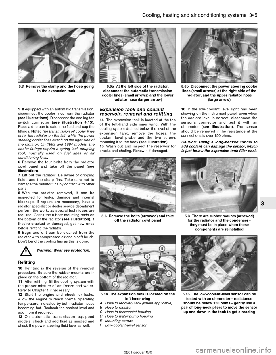
5If equipped with an automatic transmission,
disconnect the cooler lines from the radiator
(see illustrations). Disconnect the cooling fan
switch connector (see illustration 4.15).
Place a drip pan to catch the fluid and cap the
fittings. Note:The transmission oil cooler lines
enter the radiator on the left, while the power
steering cooler lines attach on the right side of
the radiator. On 1993 and 1994 models, the
cooler fittings require a spring-lock coupling
tool, normally used on fuel lines or air
conditioning lines.
6Remove the four bolts from the radiator
cowl panel and take off the panel (see
illustration).
7Lift out the radiator. Be aware of dripping
fluids and the sharp fins. Take care not to
damage the radiator fins by contact with other
parts.
8With the radiator removed, it can be
inspected for leaks, damage and internal
blockage. If repairs are necessary, have a
radiator specialist or dealer service department
perform the work, as special techniques are
required. Check the rubber mounting pads on
the bottom of the radiator (see illustration). If
they’re cracked or damaged, get new ones
before refitting the radiator.
9Bugs and dirt can be cleaned from the
radiator with compressed air and a soft brush.
Don’t bend the cooling fins as this is done.
Warning: Wear eye protection.
Refitting
10Refitting is the reverse of the removal
procedure. Be sure the rubber mounts are in
place on the bottom of the radiator.
11After refitting, fill the cooling system with
the proper mixture of antifreeze and water.
Refer to Chapter 1 if necessary.
12Start the engine and check for leaks.
Allow the engine to reach normal operating
temperature, indicated by both radiator hoses
becoming hot. Recheck the coolant level and
add more if required.
13On automatic transmission equipped
models, check and add fluid as needed and
check the power steering fluid level as well.
Expansion tank and coolant
reservoir, removal and refitting
14The expansion tank is located at the top
of the left-hand side inner wing. With the
cooling system drained below the level of the
expansion tank, remove the hoses, the
coolant level probe and the two screws
mounting it to the body (see illustration).
15Wash out and inspect the reservoir for
cracks and chafing. Renew it if damaged.16If the low-coolant level light has been
showing on the instrument panel, even when
the coolant level is correct, disconnect the
sensor’s connector and test it with an
ohmmeter (see illustration). The sensor
should be renewed if the resistance at the
connections is over 150 ohms.
Caution: Using a long-necked funnel to
add coolant can damage the sensor, which
is just below the expansion tank filler neck.
Cooling, heating and air conditioning systems 3•5
3
5.5a At the left side of the radiator,
disconnect the automatic transmission
cooler lines (small arrows) and the lower
radiator hose (larger arrow)5.5b Disconnect the power steering cooler
lines (small arrows) at the right side of the
radiator, and the upper radiator hose
(large arrow)
3261 Jaguar XJ6 5.3 Remove the clamp and the hose going
to the expansion tank
5.6 Remove the bolts (arrowed) and take
off the radiator cowl panel
5.14 The expansion tank is located on the
left inner wing
A Hose to recovery tank (where applicable)
B Hose to radiator
C Hose to thermostat housing
D Hose to water pump housing
E Mounting screws
F Low-coolant-level sensor
5.8 There are rubber mounts (arrowed)
for the radiator and the condenser -
they must be in place when these
components are reinstalled
5.16 The low-coolant-level sensor can be
tested with an ohmmeter - resistance
should be below 150 ohms - gently use a
pair of long-neck pliers to move the sensor
up and down in the tank to get a reading
Page 130 of 227

will be necessary to apply pressure to the
master cylinder piston and, at the same time,
control flow from the brake line outlets, it is
recommended that the master cylinder be
mounted in a vice. Use caution not to clamp
the vice too tightly, or the master cylinder
body might crack.
10Insert threaded plugs into the brake line
outlet holes and snug them down so that
there will be no air leakage past them, but not
so tight that they cannot be easily loosened.
11Fill the reservoir with brake fluid of the
recommended type (see Recommended
lubricants and fluidsin Chapter 1).
12Remove one plug and push the piston
assembly into the master cylinder bore to
expel the air from the master cylinder. A large
Phillips screwdriver can be used to push on
the piston assembly.
13To prevent air from being drawn back into
the master cylinder, the plug must be
replaced and tightened before releasing the
pressure on the piston assembly.
14Repeat the procedure until only brake
fluid is expelled from the brake line outlet
hole. When only brake fluid is expelled, repeat
the procedure with the other outlet hole and
plug. Be sure to keep the master cylinder
reservoir filled with brake fluid to prevent the
introduction of air into the system.
15Since high pressure is not involved in the
bench bleeding procedure, an alternative to
the removal and renewal of the plugs witheach stroke of the piston assembly is
available. Before pushing in on the piston
assembly, remove the plug as described inStep 12. Before releasing the piston, however,
instead of replacing the plug, simply put your
finger tightly over the hole to keep air from
9•8 Braking system
6.7m Apply some clean brake fluid to the
secondary piston and refit it with the slot
oriented with the stopper pin hole, so that
the stopper pin will go through the slot6.7n Apply a coat of clean brake fluid to
the primary piston and refit it into the bore6.7o Using the same technique as in
illustration 6.7f, depress the pistons and
refit the stopper pin
6.7p Refit the end plate as shown, with the
bend in the plate flange aligned with the
groove in the master cylinder flange6.7q Using a hammer and punch, stake
the end plate as shown (there’s a dimple in
the side of the plate for this purpose)6.7r Refit the grommets
3261 Jaguar XJ6
6.7s Align the reservoir pipes with the
grommets as shown . . .
6.7u Refit the reservoir roll pin . . .6.7v . . . and tap it into place
6.7t . . . and squeeze the reservoir and
master cylinder together; make sure the
reservoir is fully seated