mass airflow JAGUAR XJ6 1997 2.G Workshop Manual
[x] Cancel search | Manufacturer: JAGUAR, Model Year: 1997, Model line: XJ6, Model: JAGUAR XJ6 1997 2.GPages: 227, PDF Size: 7.2 MB
Page 97 of 227

13Allow the bellcrank to return to the idle
position and test the adjustment once again
until the correct adjustment has been attained.
11 Electronic Fuel Injection
(EFI) system-
general information
1These models are equipped with an
Electronic Fuel Injection (EFI) system. This fuel
injection system is designed by Bosch butlicensed by Lucas and is called the Lucas LH
Engine Management system. The EFI system
is composed of three basic sub systems: fuel
system, air induction system and electronic
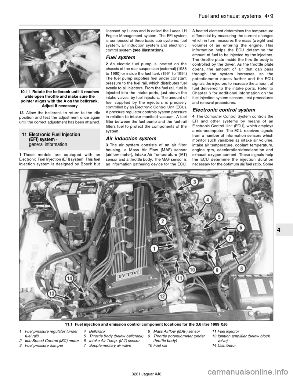
control system (see illustration).
Fuel system
2An electric fuel pump is located on the
chassis of the rear suspension (external) (1988
to 1990) or inside the fuel tank (1991 to 1994)
The fuel pump supplies fuel under constant
pressure to the fuel rail, which distributes fuel
evenly to all injectors. From the fuel rail, fuel is
injected into the intake ports, just above the
intake valves, by fuel injectors. The amount of
fuel supplied by the injectors is precisely
controlled by an Electronic Control Unit (ECU).
A pressure regulator controls system pressure
in relation to intake manifold vacuum. A fuel
filter between the fuel pump and the fuel rail
filters fuel to protect the components of the
system.
Air induction system
3The air system consists of an air filter
housing, a Mass Air Flow (MAF) sensor
(airflow meter), Intake Air Temperature (IAT)
sensor and a throttle body. The MAF sensor is
an information gathering device for the ECU.A heated element determines the temperature
differential by measuring the current changes
which in turn measures the mass (weight and
volume) of air entering the engine. This
information helps the ECU determine the
amount of fuel to be injected by the injectors.
The throttle plate inside the throttle body is
controlled by the driver. As the throttle plate
opens, the amount of air that can pass
through the system increases, so the
potentiometer opens further and the ECU
signals the injectors to increase the amount of
fuel delivered to the intake ports. Refer to
Chapter 6 for additional information on the
fuel injection system sensors, test procedures
and renewal procedures.
Electronic control system
4The Computer Control System controls the
EFI and other systems by means of an
Electronic Control Unit (ECU), which employs
a microcomputer. The ECU receives signals
from a number of information sensors which
monitor such variables as intake air volume,
intake air temperature, coolant temperature,
engine rpm, acceleration/deceleration and
exhaust oxygen content. These signals help
the ECU determine the injection duration
necessary for the optimum air/fuel ratio. Some
Fuel and exhaust systems 4•9
4
10.11 Rotate the bellcrank until it reaches
wide open throttle and make sure the
pointer aligns with the A on the bellcrank.
Adjust if necessary
11.1 Fuel injection and emission control component locations for the 3.6 litre 1989 XJ6
3261 Jaguar XJ6 1 Fuel pressure regulator (under
fuel rail)
2 Idle Speed Control (ISC) motor
3 Fuel pressure damper4 Bellcrank
5 Throttle body (below bellcrank)
6 Intake Air Temp. (IAT) sensor
7 Supplementary air valve8 Mass Airflow (MAF) sensor
9 Throttle potentiometer (under
throttle body)
10 Fuel rail11 Fuel injector
13 Ignition amplifier (below block
valve)
14 Distributor
Page 116 of 227

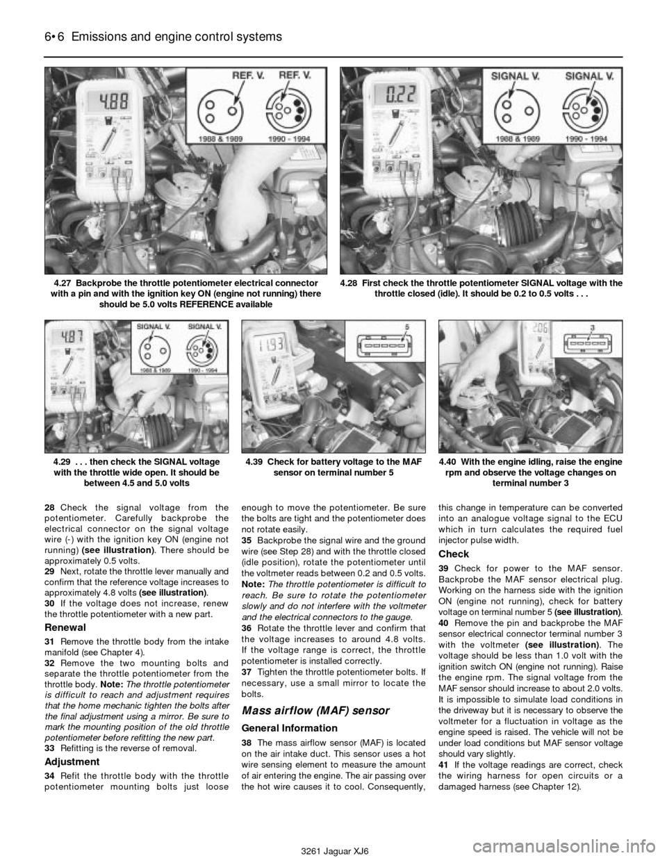
28Check the signal voltage from the
potentiometer. Carefully backprobe the
electrical connector on the signal voltage
wire (-) with the ignition key ON (engine not
running) (see illustration). There should be
approximately 0.5 volts.
29Next, rotate the throttle lever manually and
confirm that the reference voltage increases to
approximately 4.8 volts (see illustration).
30If the voltage does not increase, renew
the throttle potentiometer with a new part.
Renewal
31Remove the throttle body from the intake
manifold (see Chapter 4).
32Remove the two mounting bolts and
separate the throttle potentiometer from the
throttle body. Note:The throttle potentiometer
is difficult to reach and adjustment requires
that the home mechanic tighten the bolts after
the final adjustment using a mirror. Be sure to
mark the mounting position of the old throttle
potentiometer before refitting the new part.
33Refitting is the reverse of removal.
Adjustment
34Refit the throttle body with the throttle
potentiometer mounting bolts just looseenough to move the potentiometer. Be sure
the bolts are tight and the potentiometer does
not rotate easily.
35Backprobe the signal wire and the ground
wire (see Step 28) and with the throttle closed
(idle position), rotate the potentiometer until
the voltmeter reads between 0.2 and 0.5 volts.
Note:The throttle potentiometer is difficult to
reach. Be sure to rotate the potentiometer
slowly and do not interfere with the voltmeter
and the electrical connectors to the gauge.
36Rotate the throttle lever and confirm that
the voltage increases to around 4.8 volts.
If the voltage range is correct, the throttle
potentiometer is installed correctly.
37Tighten the throttle potentiometer bolts. If
necessary, use a small mirror to locate the
bolts.
Mass airflow (MAF) sensor
General Information
38The mass airflow sensor (MAF) is located
on the air intake duct. This sensor uses a hot
wire sensing element to measure the amount
of air entering the engine. The air passing over
the hot wire causes it to cool. Consequently,this change in temperature can be converted
into an analogue voltage signal to the ECU
which in turn calculates the required fuel
injector pulse width.
Check
39Check for power to the MAF sensor.
Backprobe the MAF sensor electrical plug.
Working on the harness side with the ignition
ON (engine not running), check for battery
voltage on terminal number 5 (see illustration).
40Remove the pin and backprobe the MAF
sensor electrical connector terminal number 3
with the voltmeter (see illustration). The
voltage should be less than 1.0 volt with the
ignition switch ON (engine not running). Raise
the engine rpm. The signal voltage from the
MAF sensor should increase to about 2.0 volts.
It is impossible to simulate load conditions in
the driveway but it is necessary to observe the
voltmeter for a fluctuation in voltage as the
engine speed is raised. The vehicle will not be
under load conditions but MAF sensor voltage
should vary slightly.
41If the voltage readings are correct, check
the wiring harness for open circuits or a
damaged harness (see Chapter 12).
6•6 Emissions and engine control systems
4.29 . . . then check the SIGNAL voltage
with the throttle wide open. It should be
between 4.5 and 5.0 volts4.39 Check for battery voltage to the MAF
sensor on terminal number 54.40 With the engine idling, raise the engine
rpm and observe the voltage changes on
terminal number 3
3261 Jaguar XJ6 4.27 Backprobe the throttle potentiometer electrical connector
with a pin and with the ignition key ON (engine not running) there
should be 5.0 volts REFERENCE available
4.28 First check the throttle potentiometer SIGNAL voltage with the
throttle closed (idle). It should be 0.2 to 0.5 volts . . .
Page 214 of 227

3261 Jaguar XJ6
Fault findingREF•13
1 Engine
Engine will not rotate when attempting to start
m mBattery terminal connections loose or corroded (Chapter 1).
m mBattery discharged or faulty (Chapter 1).
m mDamaged left rear window harness shorting against glass rail
inside door, causing battery to drain (Chapter 12).
m mAutomatic transmission not completely engaged in Park
(Chapter 7).
m mBroken, loose or disconnected wiring in the starting circuit
(Chapters 5 and 12).
m mStarter motor pinion jammed in flywheel ring gear (Chapter 5).
m mStarter solenoid faulty (Chapter 5).
m mStarter motor faulty (Chapter 5).
m mIgnition switch faulty (Chapter 12).
m mStarter pinion or flywheel teeth worn or broken (Chapter 5).
m mInternal engine problem (Chapter 2B).
m mInertia switch activated (Chapter 12).
m mStarter relay defective (Chapter 5).
Engine rotates but will not start
m
mFuel tank empty.
m mBattery discharged (engine rotates slowly) (Chapter 5).
m mBattery terminal connections loose or corroded (Chapter 1).
m mLeaking fuel injector(s), faulty fuel pump, pressure regulator, etc.
(Chapter 4).
m mFuel not reaching fuel injection system (Chapter 4).
m mIgnition components damp or damaged (Chapter 5).
m mFuel injector stuck open (Chapter 4).
m mWorn, faulty or incorrectly gapped spark plugs (Chapter 1).
m mBroken, loose or disconnected wiring in the starting circuit
(Chapter 5).
m mLoose distributor is changing ignition timing (Chapter 1).
m mBroken, loose or disconnected wires at the ignition coil or faulty
coil (Chapter 5).
m m1988 and 1989 models may have electrical connector damage
between the fuel pump relay and the fuel pump (Chapter 12).
m mCoolant temperature sensor shorting on bonnet liner (Chapter 11).
m mDefective Mass Airflow (MAF) sensor (Chapter 6).
Engine hard to start when cold
m
mBattery discharged or low (Chapter 1).
m mFuel system malfunctioning (Chapter 4).
m mInjector(s) leaking (Chapter 4).
m mDistributor rotor carbon tracked (Chapter 5).
m mWater enters the air cleaner housing near the left front wheel arch
(Chapter 4).
Engine hard to start when hot
m mAir filter clogged (Chapter 1).
m mFuel not reaching the fuel injection system (Chapter 4).
m mCorroded battery connections, especially ground (Chapter 1).
m mFuel vaporises at fuel pump inlet. Refit dual fuel pumps
(Chapter 4).
m mFuel vapours from charcoal canister enter intake during idle and
cause idling, stalling and starting problems (Chapter 6).
Starter motor noisy or excessively rough in
engagement
m mPinion or flywheel gear teeth worn or broken (Chapter 5).
m mStarter motor mounting bolts loose or missing (Chapter 5).
Engine starts but stops immediately
m
mLoose or faulty electrical connections at distributor, coil or
alternator (Chapter 5).
m mInsufficient fuel reaching the fuel injector(s) (Chapters 1 and 4).
m mDamaged fuel injection system speed sensors (Chapter 5).
m mFaulty fuel injection relays (Chapter 5).
m mLeaking threaded adapter on the EGR valve - where fitted
(Chapter 6)
Oil puddle under engine
m mSump gasket and/or sump drain bolt seal leaking (Chapter 2).
m mOil pressure sending unit leaking (Chapter 2).
m mValve cover gaskets leaking (Chapter 2).
m mEngine oil seals leaking (Chapter 2).
m mCylinder head rear plate gasket leaking (Chapter 2).
m mAlternator mounting bolt threads leaking oil (Chapter 5).
m mOil cooler or oil cooler lines leaking (Chapter 3).
Engine misses while idling or idles erratically
m
mVacuum leakage (Chapter 2).
m mAir filter clogged (Chapter 1).
m mFuel pump not delivering sufficient fuel to the fuel injection system
(Chapter 4).
m mLeaking head gasket (Chapter 2).
m mTiming belt/chain and/or sprockets worn (Chapter 2).
m mCamshaft lobes worn (Chapter 2).
m mEGR valve stuck open - where fitted (Chapter 6).
Engine misses at idle speed
m
mSpark plugs worn or not gapped properly (Chapter 1).
m mFaulty spark plug leads (Chapter 1).
m mVacuum leaks (Chapter 1).
m mIncorrect ignition timing (Chapter 5).
m mUneven or low compression (Chapter 2).
m mRestricted EGR vacuum hose - where fitted (Chapter 6).
Engine misses throughout driving speed range
m
mFuel filter clogged and/or impurities in the fuel system (Chapter 1).
m mLow fuel output at the injectors (Chapter 4).
m mFaulty or incorrectly gapped spark plugs (Chapter 1).
m mIncorrect ignition timing (Chapter 5).
m mCracked distributor cap, disconnected distributor wires or
damaged distributor components (Chapter 1).
m mLeaking spark plug leads (Chapter 1).
m mFaulty emission system components (Chapter 6).
m mLow or uneven cylinder compression pressures (Chapter 2).
m mWeak or faulty ignition system (Chapter 5).
m mVacuum leak in fuel injection system, intake manifold or vacuum
hoses (Chapter 4).
m mCrankshaft sensor teeth damaged or missing (see Chapter 12).
m mDistributor installed incorrectly (see Chapter 5)
Engine stumbles on acceleration
m
mSpark plugs fouled (Chapter 1).
m mFuel injection system malfunctioning (Chapter 4).
m mFuel filter clogged (Chapters 1 and 4).
m mIncorrect ignition timing (Chapter 5).
m mIntake manifold air leak (Chapter 4).
m mCollapsed or damaged fuel tank caused by blocked EVAP system
- where fitted (see Chapter 6).
Page 224 of 227

3261 Jaguar XJ6
IndexREF•23
EEarth check - 12•2
ECU -6•2
EGR gas temperature sensor -6•7
Electric shock -0•5
Electric windows - 12•13
Electrical equipment -1•14, REF•9
Electrical system fault finding - 12•1, REF•17
Electronic control system and ECU -4•9, 6•2
Electronic Fuel Injection (EFI) system -4•9, 4•10
Emissions and engine control systems-6•1et seq
Engine electrical systems-5•1et seq
Engine in-car repair procedures-2A•1et seq
Engine fault finding - ref•13,ref•14
Engine oil -0•11, 0•16, 1•2, 1•6
Engine removal and overhaul procedures-2B•1et seq
Environmental considerations - REF•5
Evaporative Emission Control (EVAP) system -6•10
Evaporator and expansion valve -3•14
Exhaust emission checks - REF•11
Exhaust Gas Recirculation (EGR) system -6•9
Exhaust manifolds -2A•4
Exhaust system -1•11, 4•2, 4•14, REF•10
Expansion tank -3•4, 3•5
FFans -3•3
Fault finding- REF•12et seq
ABS -9•2
automatic transmission - 7•1, REF•15
brakes - REF•15, REF•16
cooling system - REF•14
electrical system - 12•1, REF•17
engine - REF•13, REF•14
fuel system - REF•14
suspension and steering systems - REF•16, REF•17
Filling (bodywork repair) - 11•2
Filters
automatic transmission fluid - 1•19
fuel - 1•15
oil - 1•6
Fire -0•5
Fluids -0•16
Fuel and exhaust systems-4•1et seq, REF•11
Fuel filter -1•15
Fuel gauge - 12•7
Fuel pressure relief -4•2
Fuel system fault finding - REF•14
Fume or gas intoxication -0•5
Fuses -0•15, 12•2
GGaiters - 10•9
Gashes - 11•2
Gaskets - REF•5
Glass - 11•3, 11•10, 11•11, 12•13
Glossary of technical terms- REF•3, REF•18et seq
Glove box - 11•13
Grille - 11•5
HHandbrake -1•12, 1•20, 9•1, 9•10, 9•11, REF•8
Handles - 11•9, 11•10
Hazard flasher - 12•4
HC emissions - REF•11
Headlights -1•18, 12•9, 12•10, 12•11
Heated rear window - 12•8
Heater -3•2, 3•7, 3•9, 3•10, 3•11, 3•12
High-mounted brake light - 12•12
Hinges - 11•3
Horn - 12•11
Hoses -1•10
Hub bearings - 1•17, 10•8
Hydraulic system -0•16
Hydrofluoric acid -0•5
IIdle Speed Control (ISC) motor -4•11
Ignition switch - 12•6
Ignition system -1•15
In-tank fuel pumps -4•4
Indicators - 12•4, 12•11, 12•12
Inertia switch -4•1, 12•12
Information sensors -6•3
Injectors -4•12
Instruments - 1•14, 11•12, 12•6, 12•7, 12•12
Intake Air Temperature (IAT) sensor -6•7
Intake manifold -2A•4
Interior lights - 12•12
Introduction -0•4
JJacking - REF•1
Joint mating faces - REF•5
Jump starting -0•7
KKickdown cable -7•2
Knee bolster - 11•13
LLatch - 11•4, 11•7, 11•9
Leaks -0•9, 1•10, 7•2
Locknuts,locktabs and washers - REF•5
Locks - 11•3, 11•7, 11•9, 12•6
Lubricants -0•16
MMain bearings -2B•13, 2B•16
Manifolds -2A•4
Manual valve -7•7
Mass Airflow (MAF) sensor -6•6
Master cylinder -9•6
Mirrors - 11•11, 12•14, REF•8
MOT test checks- REF•8et seq
Mounts -2A•18, 7•8
Multi Point Fuel Injection (MPFI) system -4•1