JEEP CHEROKEE 1995 Service Repair Manual
Manufacturer: JEEP, Model Year: 1995, Model line: CHEROKEE, Model: JEEP CHEROKEE 1995Pages: 2198, PDF Size: 82.83 MB
Page 1671 of 2198
OVERHAUL CLEANING AND INSPECTION
Clean the transfer case components thoroughly
with solvent. Remove all traces of sealer from the
case and retainer seal surfaces.
Clean the oil pickup screen with solvent. Shake ex-
cess solvent from screen and allow it air dry. Use
compressed air to remove solvent residue from all oil
feed passages and channels in the case halves.
Inspect the splines and bearing surfaces on the
both shafts. Replace either shaft as necessary if wear,
or damage is evident.
Check condition of the shift forks, fork pads and
shift rail. Minor scratches/nicks on the rail can be
smoothed with 320/400 grit emery cloth. Replace the
mode fork pads if worn. Replace the range fork if the
pads are worn, missing, or damaged.
On synchro equipped models, inspect the synchro
sleeve, hub, struts, springs, and the stop ring. Re-
place worn, or damaged parts as necessary.
Do not attempt to salvage and reuse snap rings
that were bent, or distorted. It is recommended that
all snap rings be replaced during overhaul.Replace the front yoke nut as it should not be re-
used. Also replace the rubber seal if worn, cut, or
torn.
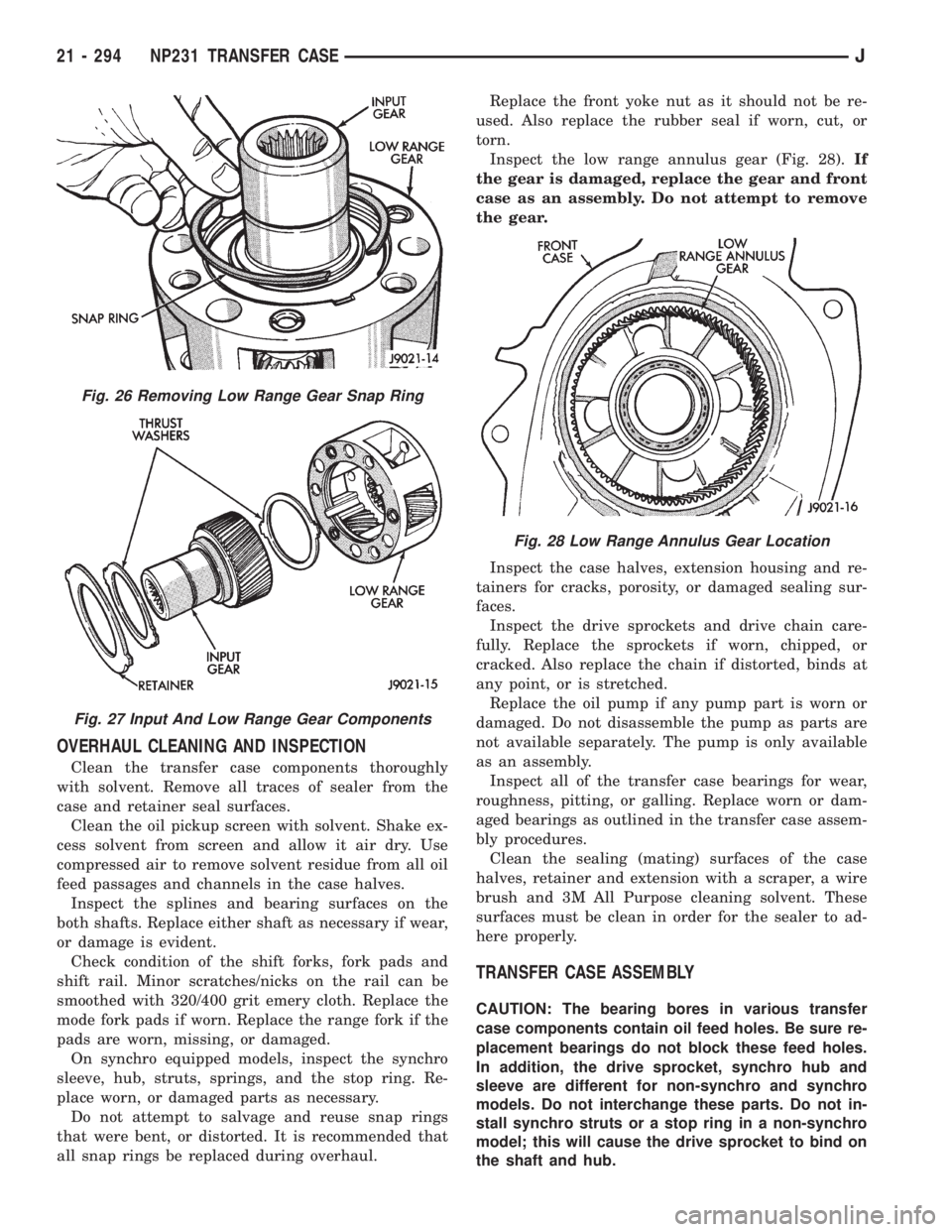
Inspect the low range annulus gear (Fig. 28).If
the gear is damaged, replace the gear and front
case as an assembly. Do not attempt to remove
the gear.
Inspect the case halves, extension housing and re-
tainers for cracks, porosity, or damaged sealing sur-
faces.
Inspect the drive sprockets and drive chain care-
fully. Replace the sprockets if worn, chipped, or
cracked. Also replace the chain if distorted, binds at
any point, or is stretched.
Replace the oil pump if any pump part is worn or
damaged. Do not disassemble the pump as parts are
not available separately. The pump is only available
as an assembly.
Inspect all of the transfer case bearings for wear,
roughness, pitting, or galling. Replace worn or dam-
aged bearings as outlined in the transfer case assem-
bly procedures.
Clean the sealing (mating) surfaces of the case
halves, retainer and extension with a scraper, a wire
brush and 3M All Purpose cleaning solvent. These
surfaces must be clean in order for the sealer to ad-
here properly.
TRANSFER CASE ASSEMBLY
CAUTION: The bearing bores in various transfer
case components contain oil feed holes. Be sure re-
placement bearings do not block these feed holes.
In addition, the drive sprocket, synchro hub and
sleeve are different for non-synchro and synchro
models. Do not interchange these parts. Do not in-
stall synchro struts or a stop ring in a non-synchro
model; this will cause the drive sprocket to bind on
the shaft and hub.
Fig. 26 Removing Low Range Gear Snap Ring
Fig. 27 Input And Low Range Gear Components
Fig. 28 Low Range Annulus Gear Location
21 - 294 NP231 TRANSFER CASEJ
Page 1672 of 2198
FRONT CASE ASSEMBLY
(1) Lubricate components with automatic transmis-
sion fluid (or petroleum jelly where indicated) during
assembly.
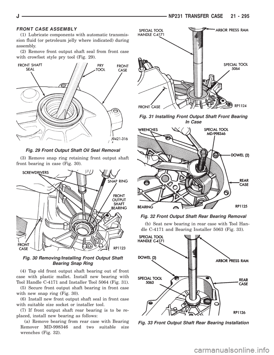
(2) Remove front output shaft seal from front case
with crowfoot style pry tool (Fig. 29).
(3) Remove snap ring retaining front output shaft
front bearing in case (Fig. 30).
(4) Tap old front output shaft bearing out of front
case with plastic mallet. Install new bearing with
Tool Handle C-4171 and Installer Tool 5064 (Fig. 31).
(5) Secure front output shaft bearing in front case
with new snap ring (Fig. 30).
(6) Install new front output shaft seal in front case
with suitable size socket or installer tool.
(7) If front output shaft rear bearing is to be re-
placed, install new bearing as follows:
(a) Remove bearing from rear case with Bearing
Remover MD-998346 and two suitable size
wrenches (Fig. 32).(b) Seat new bearing in rear case with Tool Han-
dle C-4171 and Bearing Installer 5063 (Fig. 33).
Fig. 29 Front Output Shaft Oil Seal Removal
Fig. 30 Removing/Installing Front Output Shaft
Bearing Snap Ring
Fig. 31 Installing Front Output Shaft Front Bearing
In Case
Fig. 32 Front Output Shaft Rear Bearing Removal
Fig. 33 Front Output Shaft Rear Bearing Installation
JNP231 TRANSFER CASE 21 - 295
Page 1673 of 2198
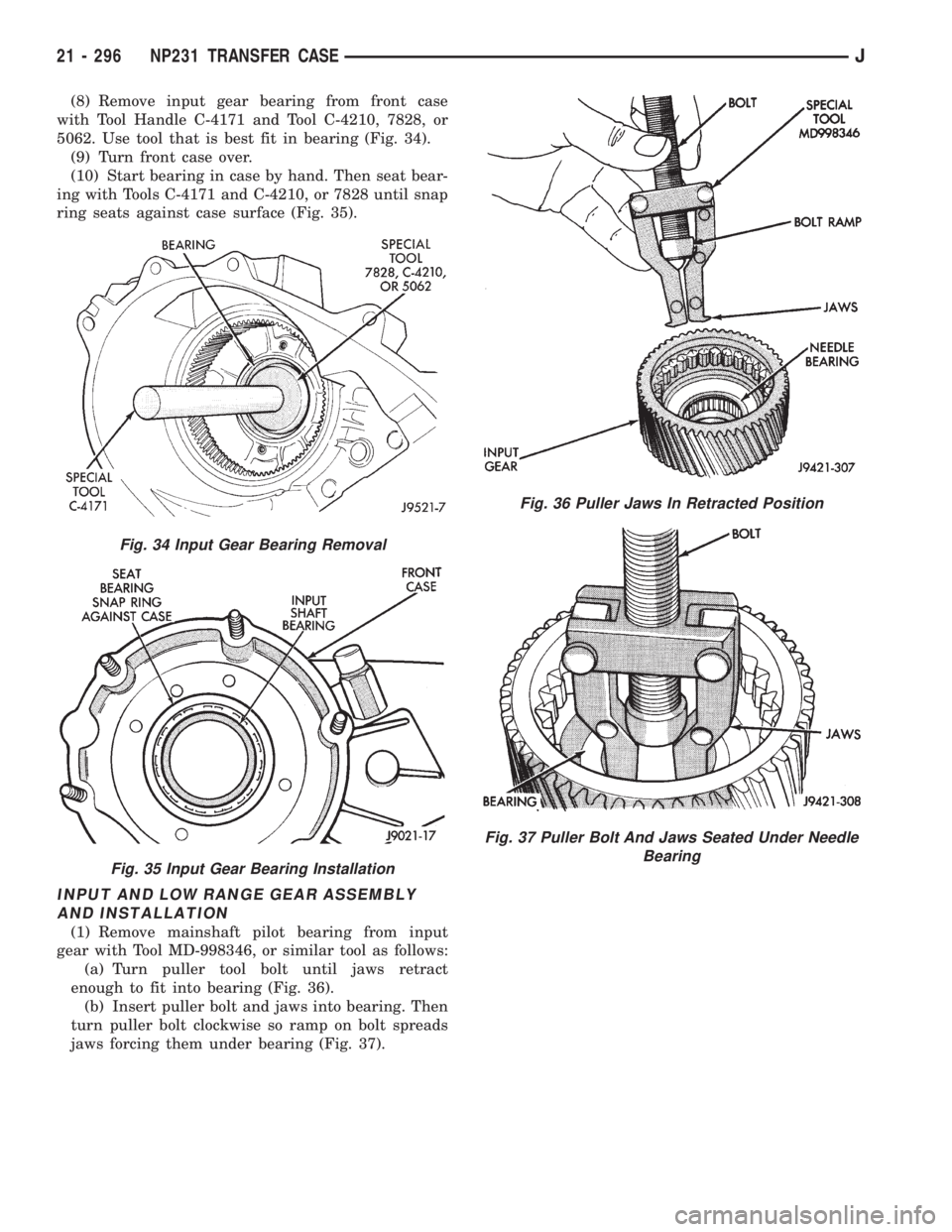
(8) Remove input gear bearing from front case
with Tool Handle C-4171 and Tool C-4210, 7828, or
5062. Use tool that is best fit in bearing (Fig. 34).
(9) Turn front case over.
(10) Start bearing in case by hand. Then seat bear-
ing with Tools C-4171 and C-4210, or 7828 until snap
ring seats against case surface (Fig. 35).
INPUT AND LOW RANGE GEAR ASSEMBLY
AND INSTALLATION
(1) Remove mainshaft pilot bearing from input
gear with Tool MD-998346, or similar tool as follows:
(a) Turn puller tool bolt until jaws retract
enough to fit into bearing (Fig. 36).
(b) Insert puller bolt and jaws into bearing. Then
turn puller bolt clockwise so ramp on bolt spreads
jaws forcing them under bearing (Fig. 37).
Fig. 34 Input Gear Bearing Removal
Fig. 35 Input Gear Bearing Installation
Fig. 36 Puller Jaws In Retracted Position
Fig. 37 Puller Bolt And Jaws Seated Under Needle
Bearing
21 - 296 NP231 TRANSFER CASEJ
Page 1674 of 2198
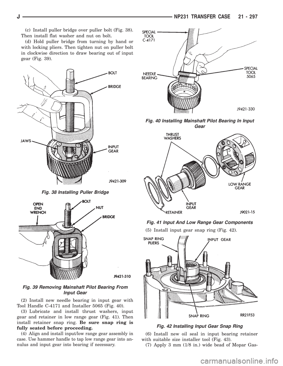
(c) Install puller bridge over puller bolt (Fig. 38).
Then install flat washer and nut on bolt.
(d) Hold puller bridge from turning by hand or
with locking pliers. Then tighten nut on puller bolt
in clockwise direction to draw bearing out of input
gear (Fig. 39).
(2) Install new needle bearing in input gear with
Tool Handle C-4171 and Installer 5065 (Fig. 40).
(3) Lubricate and install thrust washers, input
gear and retainer in low range gear (Fig. 41). Then
install retainer snap ring.Be sure snap ring is
fully seated before proceeding.
(4) Align and install input/low range gear assembly in
case. Use hammer handle to tap low range gear into an-
nulus and input gear into bearing if necessary.
(5) Install input gear snap ring (Fig. 42).
(6) Install new oil seal in input bearing retainer
with suitable size installer tool (Fig. 43).
(7) Apply 3 mm (1/8 in.) wide bead of Mopar Gas-
Fig. 38 Installing Puller Bridge
Fig. 39 Removing Mainshaft Pilot Bearing From
Input Gear
Fig. 40 Installing Mainshaft Pilot Bearing In Input
Gear
Fig. 41 Input And Low Range Gear Components
Fig. 42 Installing Input Gear Snap Ring
JNP231 TRANSFER CASE 21 - 297
Page 1675 of 2198
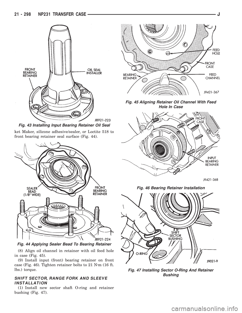
ket Maker, silicone adhesive/sealer, or Loctite 518 to
front bearing retainer seal surface (Fig. 44).
(8) Align oil channel in retainer with oil feed hole
in case (Fig. 45).
(9) Install input (front) bearing retainer on front
case (Fig. 46). Tighten retainer bolts to 21 Nzm (16 ft.
lbs.) torque.
SHIFT SECTOR, RANGE FORK AND SLEEVE
INSTALLATION
(1) Install new sector shaft O-ring and retainer
bushing (Fig. 47).
Fig. 43 Installing Input Bearing Retainer Oil Seal
Fig. 44 Applying Sealer Bead To Bearing Retainer
Fig. 45 Aligning Retainer Oil Channel With Feed
Hole In Case
Fig. 46 Bearing Retainer Installation
Fig. 47 Installing Sector O-Ring And Retainer
Bushing
21 - 298 NP231 TRANSFER CASEJ
Page 1676 of 2198
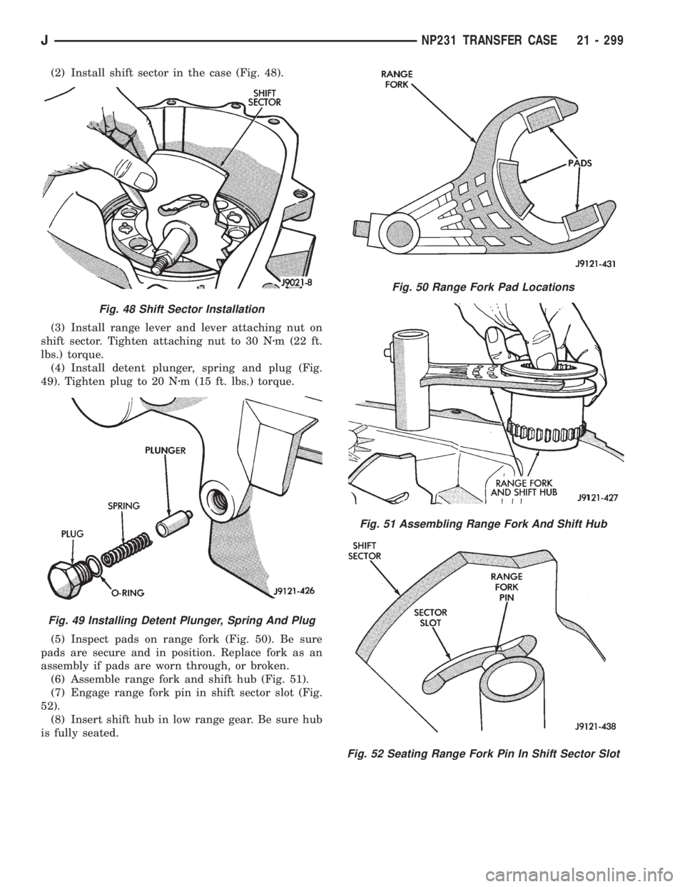
(2) Install shift sector in the case (Fig. 48).
(3) Install range lever and lever attaching nut on
shift sector. Tighten attaching nut to 30 Nzm (22 ft.
lbs.) torque.
(4) Install detent plunger, spring and plug (Fig.
49). Tighten plug to 20 Nzm (15 ft. lbs.) torque.
(5) Inspect pads on range fork (Fig. 50). Be sure
pads are secure and in position. Replace fork as an
assembly if pads are worn through, or broken.
(6) Assemble range fork and shift hub (Fig. 51).
(7) Engage range fork pin in shift sector slot (Fig.
52).
(8) Insert shift hub in low range gear. Be sure hub
is fully seated.
Fig. 48 Shift Sector Installation
Fig. 49 Installing Detent Plunger, Spring And Plug
Fig. 50 Range Fork Pad Locations
Fig. 51 Assembling Range Fork And Shift Hub
Fig. 52 Seating Range Fork Pin In Shift Sector Slot
JNP231 TRANSFER CASE 21 - 299
Page 1677 of 2198
MAINSHAFT ASSEMBLY
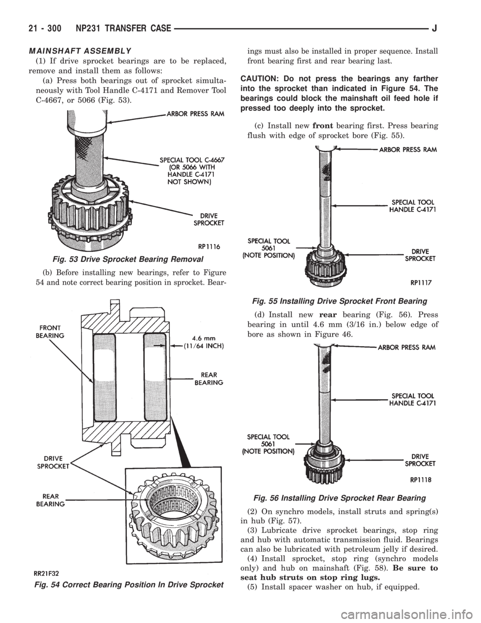
(1) If drive sprocket bearings are to be replaced,
remove and install them as follows:
(a) Press both bearings out of sprocket simulta-
neously with Tool Handle C-4171 and Remover Tool
C-4667, or 5066 (Fig. 53).
(b) Before installing new bearings, refer to Figure
54 and note correct bearing position in sprocket. Bear-ings must also be installed in proper sequence. Install
front bearing first and rear bearing last.
CAUTION: Do not press the bearings any farther
into the sprocket than indicated in Figure 54. The
bearings could block the mainshaft oil feed hole if
pressed too deeply into the sprocket.
(c) Install newfrontbearing first. Press bearing
flush with edge of sprocket bore (Fig. 55).
(d) Install newrearbearing (Fig. 56). Press
bearing in until 4.6 mm (3/16 in.) below edge of
bore as shown in Figure 46.
(2) On synchro models, install struts and spring(s)
in hub (Fig. 57).
(3) Lubricate drive sprocket bearings, stop ring
and hub with automatic transmission fluid. Bearings
can also be lubricated with petroleum jelly if desired.
(4) Install sprocket, stop ring (synchro models
only) and hub on mainshaft (Fig. 58).Be sure to
seat hub struts on stop ring lugs.
(5) Install spacer washer on hub, if equipped.
Fig. 54 Correct Bearing Position In Drive Sprocket
Fig. 53 Drive Sprocket Bearing Removal
Fig. 55 Installing Drive Sprocket Front Bearing
Fig. 56 Installing Drive Sprocket Rear Bearing
21 - 300 NP231 TRANSFER CASEJ
Page 1678 of 2198
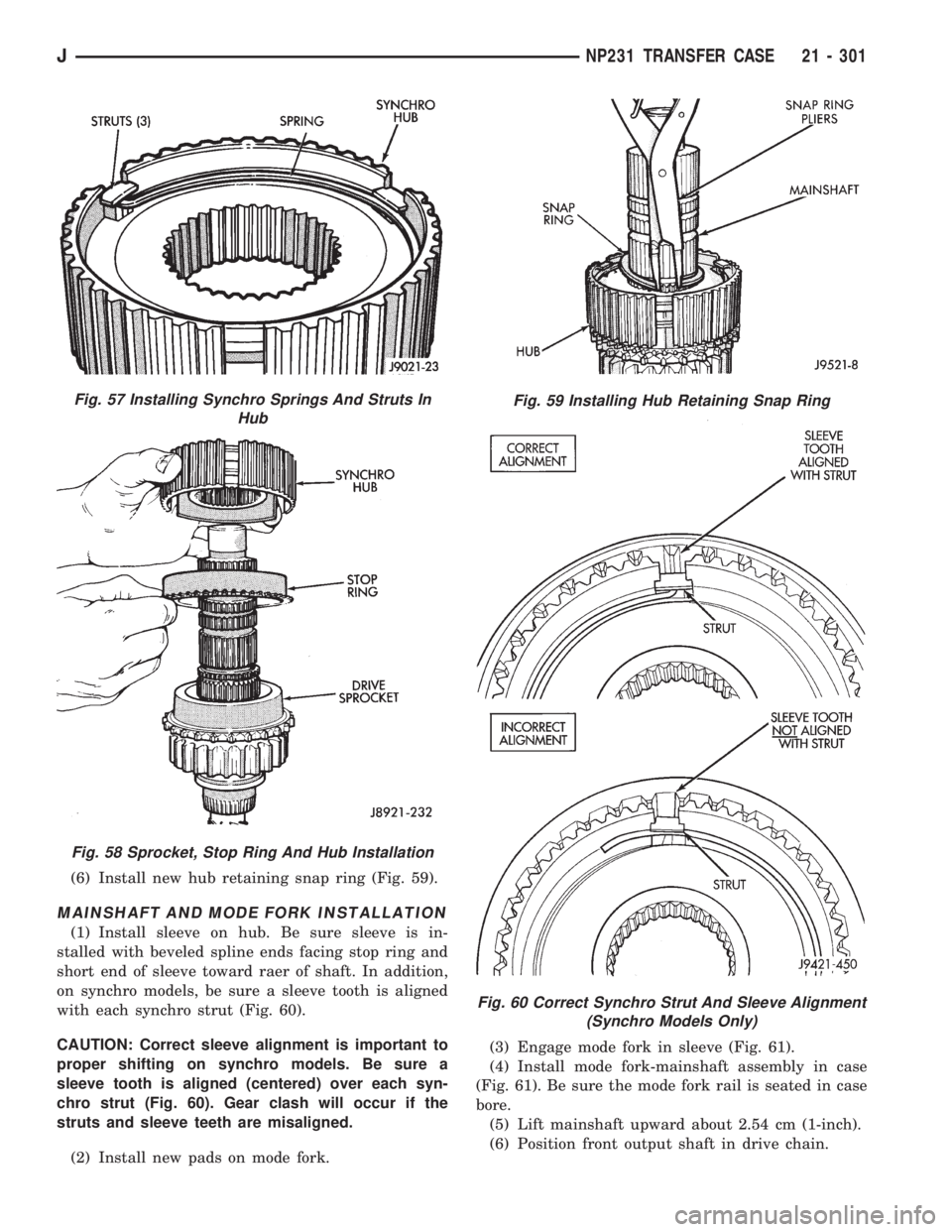
(6) Install new hub retaining snap ring (Fig. 59).
MAINSHAFT AND MODE FORK INSTALLATION
(1) Install sleeve on hub. Be sure sleeve is in-
stalled with beveled spline ends facing stop ring and
short end of sleeve toward raer of shaft. In addition,
on synchro models, be sure a sleeve tooth is aligned
with each synchro strut (Fig. 60).
CAUTION: Correct sleeve alignment is important to
proper shifting on synchro models. Be sure a
sleeve tooth is aligned (centered) over each syn-
chro strut (Fig. 60). Gear clash will occur if the
struts and sleeve teeth are misaligned.
(2) Install new pads on mode fork.(3) Engage mode fork in sleeve (Fig. 61).
(4) Install mode fork-mainshaft assembly in case
(Fig. 61). Be sure the mode fork rail is seated in case
bore.
(5) Lift mainshaft upward about 2.54 cm (1-inch).
(6) Position front output shaft in drive chain.
Fig. 57 Installing Synchro Springs And Struts In
Hub
Fig. 58 Sprocket, Stop Ring And Hub Installation
Fig. 59 Installing Hub Retaining Snap Ring
Fig. 60 Correct Synchro Strut And Sleeve Alignment
(Synchro Models Only)
JNP231 TRANSFER CASE 21 - 301
Page 1679 of 2198
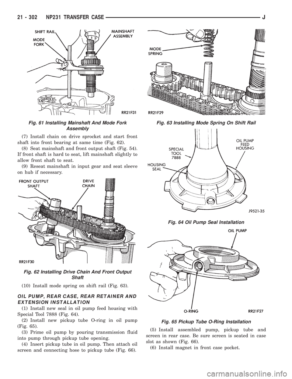
(7) Install chain on drive sprocket and start front
shaft into front bearing at same time (Fig. 62).
(8) Seat mainshaft and front output shaft (Fig. 54).
If front shaft is hard to seat, lift mainshaft slightly to
allow front shaft to seat.
(9) Reseat mainshaft in input gear and seat sleeve
on hub if necessary.
(10) Install mode spring on shift rail (Fig. 63).
OIL PUMP, REAR CASE, REAR RETAINER AND
EXTENSION INSTALLATION
(1) Install new seal in oil pump feed housing with
Special Tool 7888 (Fig. 64).
(2) Install new pickup tube O-ring in oil pump
(Fig. 65).
(3) Prime oil pump by pouring transmission fluid
into pump through pickup tube opening.
(4) Insert pickup tube in oil pump. Then attach oil
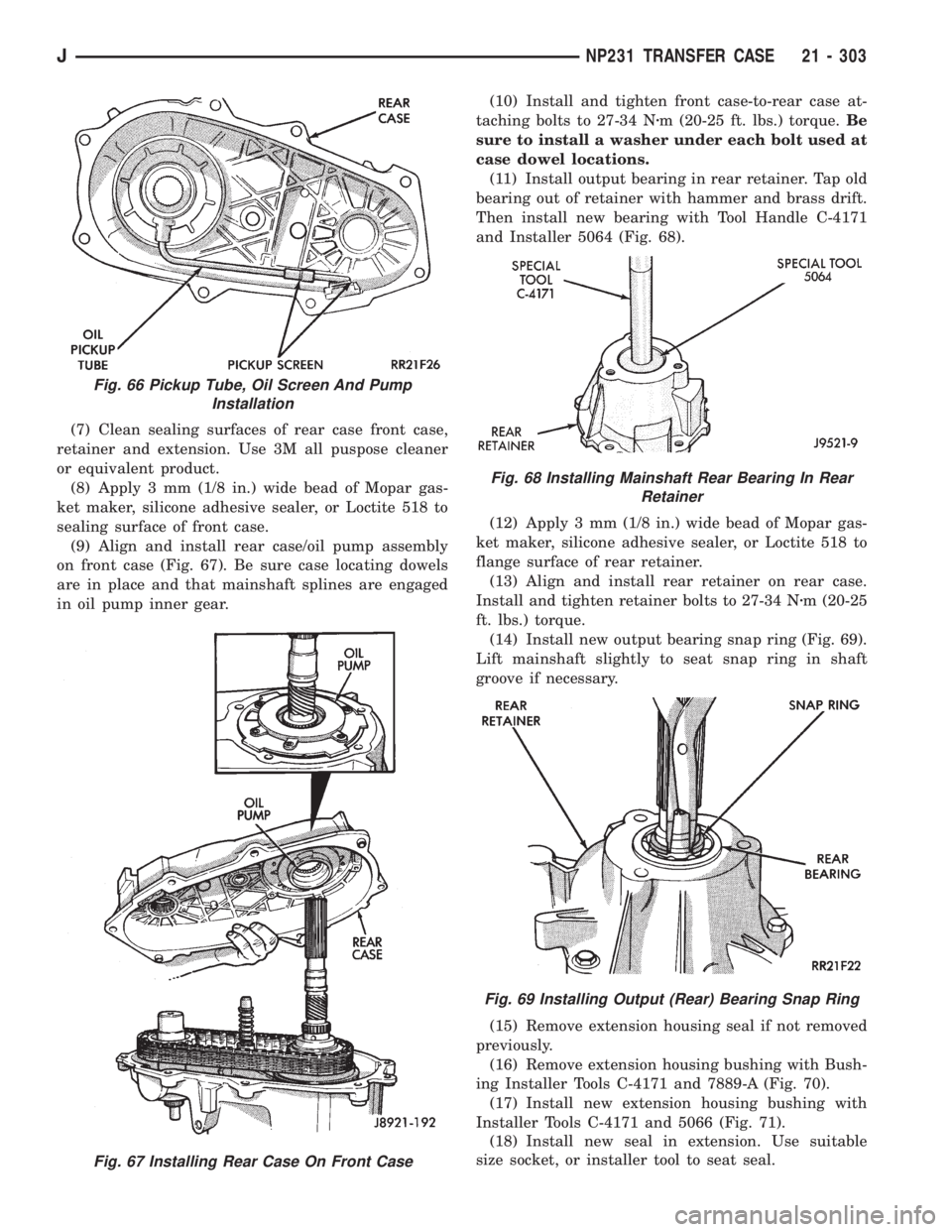
screen and connecting hose to pickup tube (Fig. 66).(5) Install assembled pump, pickup tube and
screen in rear case. Be sure screen is seated in case
slot as shown (Fig. 66).
(6) Install magnet in front case pocket.
Fig. 61 Installing Mainshaft And Mode Fork
Assembly
Fig. 62 Installing Drive Chain And Front Output
Shaft
Fig. 63 Installing Mode Spring On Shift Rail
Fig. 64 Oil Pump Seal Installation
Fig. 65 Pickup Tube O-Ring Installation
21 - 302 NP231 TRANSFER CASEJ
Page 1680 of 2198
(7) Clean sealing surfaces of rear case front case,
retainer and extension. Use 3M all puspose cleaner
or equivalent product.
(8) Apply 3 mm (1/8 in.) wide bead of Mopar gas-
ket maker, silicone adhesive sealer, or Loctite 518 to
sealing surface of front case.
(9) Align and install rear case/oil pump assembly
on front case (Fig. 67). Be sure case locating dowels
are in place and that mainshaft splines are engaged
in oil pump inner gear.(10) Install and tighten front case-to-rear case at-
taching bolts to 27-34 Nzm (20-25 ft. lbs.) torque.Be
sure to install a washer under each bolt used at
case dowel locations.
(11) Install output bearing in rear retainer. Tap old
bearing out of retainer with hammer and brass drift.
Then install new bearing with Tool Handle C-4171
and Installer 5064 (Fig. 68).
(12) Apply 3 mm (1/8 in.) wide bead of Mopar gas-
ket maker, silicone adhesive sealer, or Loctite 518 to
flange surface of rear retainer.
(13) Align and install rear retainer on rear case.
Install and tighten retainer bolts to 27-34 Nzm (20-25
ft. lbs.) torque.
(14) Install new output bearing snap ring (Fig. 69).
Lift mainshaft slightly to seat snap ring in shaft
groove if necessary.
(15) Remove extension housing seal if not removed
previously.
(16) Remove extension housing bushing with Bush-
ing Installer Tools C-4171 and 7889-A (Fig. 70).
(17) Install new extension housing bushing with
Installer Tools C-4171 and 5066 (Fig. 71).
(18) Install new seal in extension. Use suitable
size socket, or installer tool to seat seal.
Fig. 67 Installing Rear Case On Front Case
Fig. 66 Pickup Tube, Oil Screen And Pump
Installation
Fig. 68 Installing Mainshaft Rear Bearing In Rear
Retainer
Fig. 69 Installing Output (Rear) Bearing Snap Ring
JNP231 TRANSFER CASE 21 - 303