JEEP CHEROKEE 1995 Service Repair Manual
Manufacturer: JEEP, Model Year: 1995, Model line: CHEROKEE, Model: JEEP CHEROKEE 1995Pages: 2198, PDF Size: 82.83 MB
Page 1641 of 2198
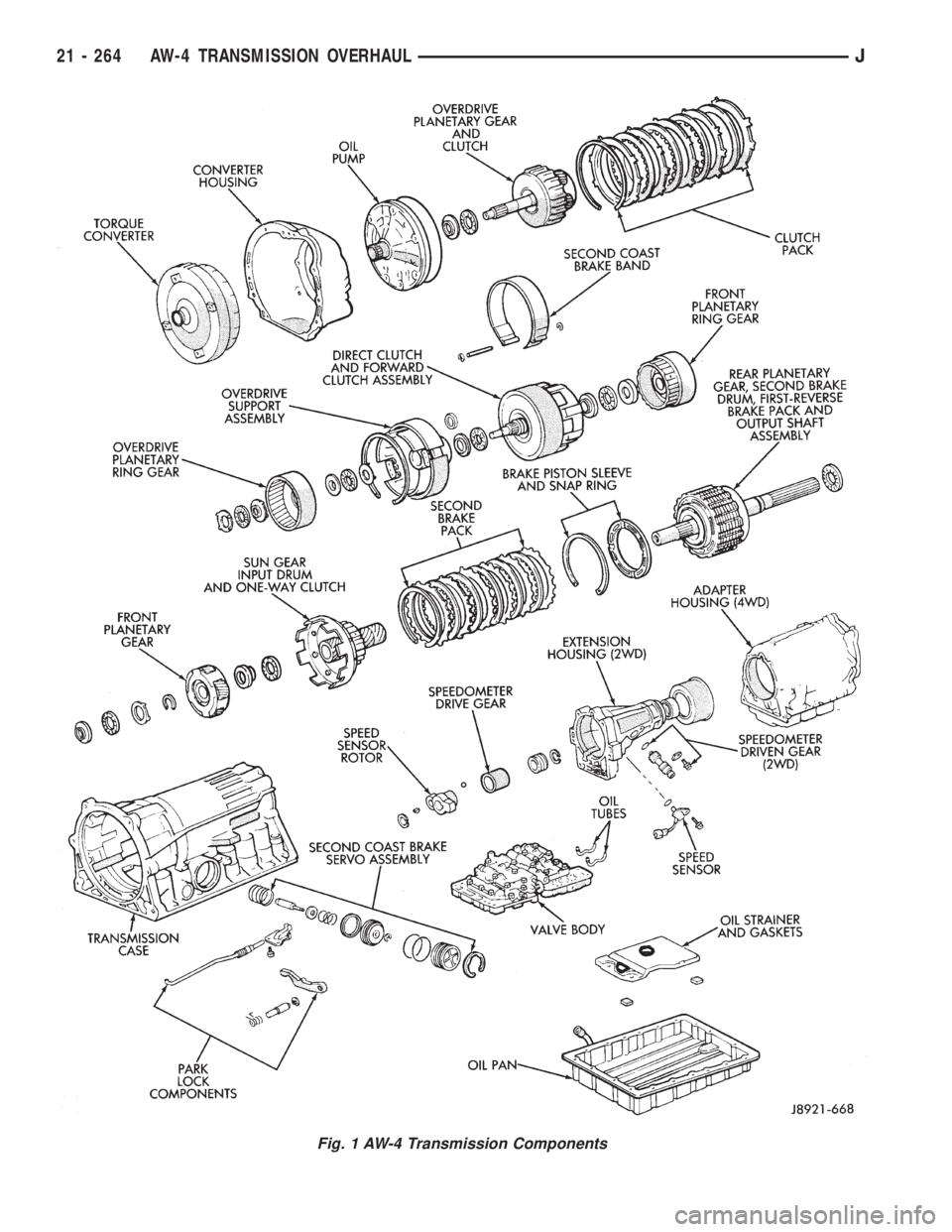
Fig. 1 AW-4 Transmission Components
21 - 264 AW-4 TRANSMISSION OVERHAULJ
Page 1642 of 2198
TRANSMISSION ASSEMBLY AND ADJUSTMENT
(1) During assembly, lubricate components with
transmission fluid or petroleum jelly as indicated.
(2) If any of the transmission components are still
assembled after overhaul checking procedures, disas-
semble as necessary in preparation for transmission
assembly.
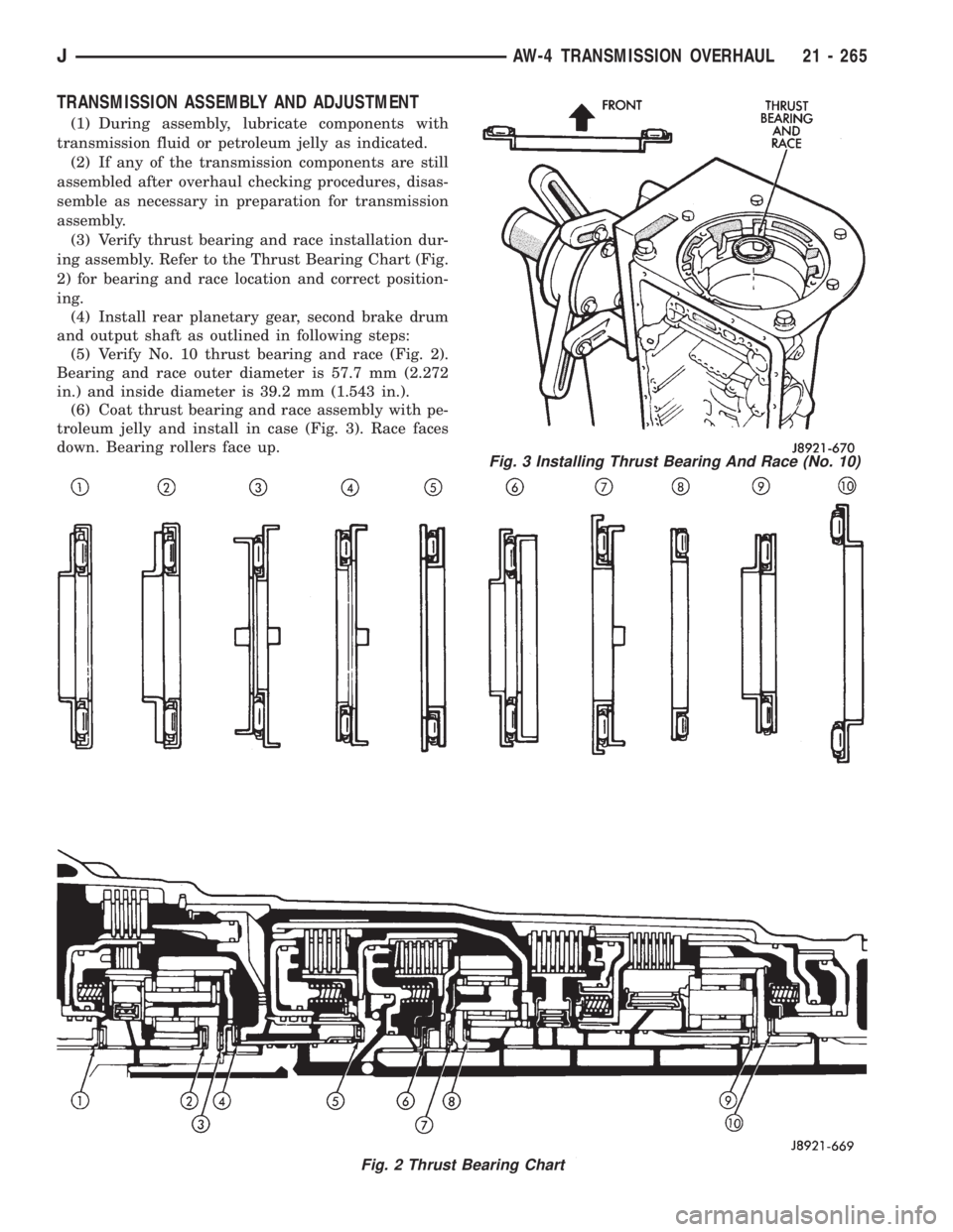
(3) Verify thrust bearing and race installation dur-
ing assembly. Refer to the Thrust Bearing Chart (Fig.
2) for bearing and race location and correct position-
ing.
(4) Install rear planetary gear, second brake drum
and output shaft as outlined in following steps:
(5) Verify No. 10 thrust bearing and race (Fig. 2).
Bearing and race outer diameter is 57.7 mm (2.272
in.) and inside diameter is 39.2 mm (1.543 in.).
(6) Coat thrust bearing and race assembly with pe-
troleum jelly and install in case (Fig. 3). Race faces
down. Bearing rollers face up.
Fig. 2 Thrust Bearing Chart
Fig. 3 Installing Thrust Bearing And Race (No. 10)
JAW-4 TRANSMISSION OVERHAUL 21 - 265
Page 1643 of 2198
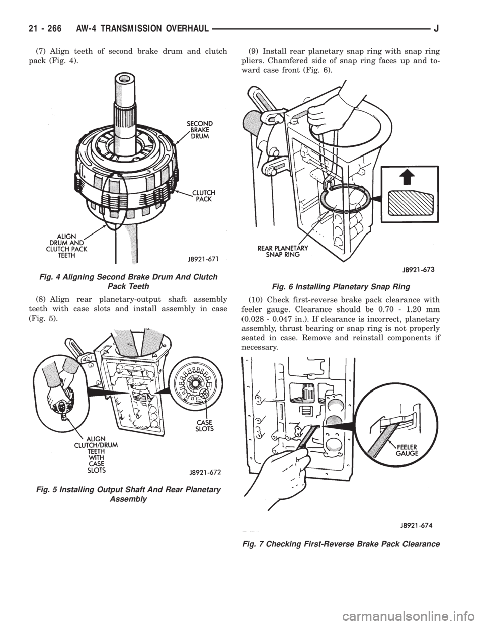
(7) Align teeth of second brake drum and clutch
pack (Fig. 4).
(8) Align rear planetary-output shaft assembly
teeth with case slots and install assembly in case
(Fig. 5).(9) Install rear planetary snap ring with snap ring
pliers. Chamfered side of snap ring faces up and to-
ward case front (Fig. 6).
(10) Check first-reverse brake pack clearance with
feeler gauge. Clearance should be 0.70 - 1.20 mm
(0.028 - 0.047 in.). If clearance is incorrect, planetary
assembly, thrust bearing or snap ring is not properly
seated in case. Remove and reinstall components if
necessary.
Fig. 4 Aligning Second Brake Drum And Clutch
Pack Teeth
Fig. 5 Installing Output Shaft And Rear Planetary
Assembly
Fig. 6 Installing Planetary Snap Ring
Fig. 7 Checking First-Reverse Brake Pack Clearance
21 - 266 AW-4 TRANSMISSION OVERHAULJ
Page 1644 of 2198
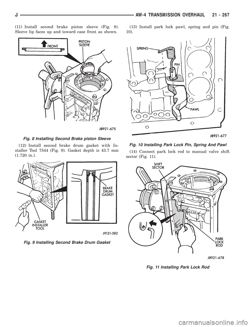
(11) Install second brake piston sleeve (Fig. 8).
Sleeve lip faces up and toward case front as shown.
(12) Install second brake drum gasket with In-
staller Tool 7544 (Fig. 9). Gasket depth is 43.7 mm
(1.720 in.).(13) Install park lock pawl, spring and pin (Fig.
10).
(14) Connect park lock rod to manual valve shift
sector (Fig. 11).
Fig. 8 Installing Second Brake piston Sleeve
Fig. 9 Installing Second Brake Drum Gasket
Fig. 10 Installing Park Lock Pin, Spring And Pawl
Fig. 11 Installing Park Lock Rod
JAW-4 TRANSMISSION OVERHAUL 21 - 267
Page 1645 of 2198
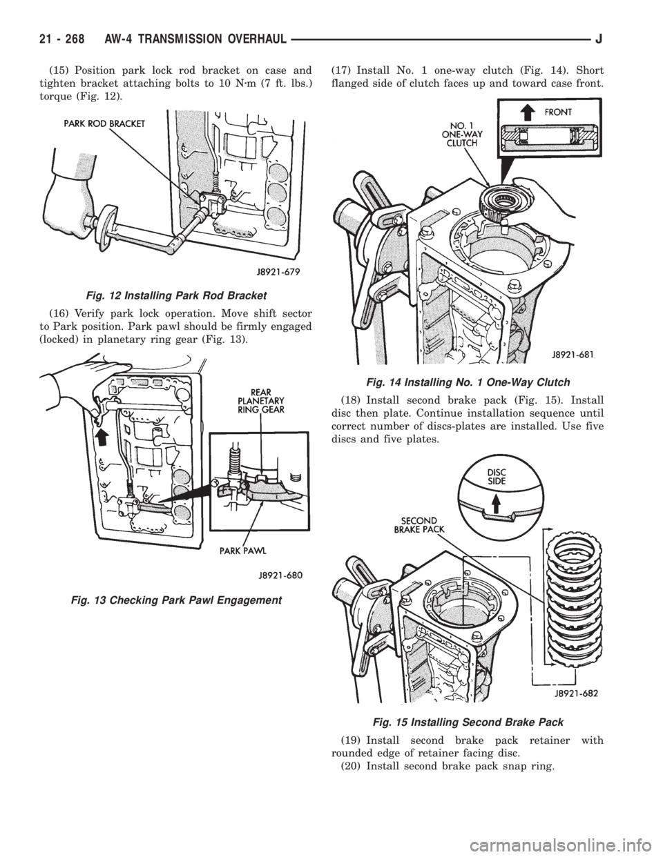
(15) Position park lock rod bracket on case and
tighten bracket attaching bolts to 10 Nzm (7 ft. lbs.)
torque (Fig. 12).
(16) Verify park lock operation. Move shift sector
to Park position. Park pawl should be firmly engaged
(locked) in planetary ring gear (Fig. 13).(17) Install No. 1 one-way clutch (Fig. 14). Short
flanged side of clutch faces up and toward case front.
(18) Install second brake pack (Fig. 15). Install
disc then plate. Continue installation sequence until
correct number of discs-plates are installed. Use five
discs and five plates.
(19) Install second brake pack retainer with
rounded edge of retainer facing disc.
(20) Install second brake pack snap ring.
Fig. 12 Installing Park Rod Bracket
Fig. 13 Checking Park Pawl Engagement
Fig. 14 Installing No. 1 One-Way Clutch
Fig. 15 Installing Second Brake Pack
21 - 268 AW-4 TRANSMISSION OVERHAULJ
Page 1646 of 2198
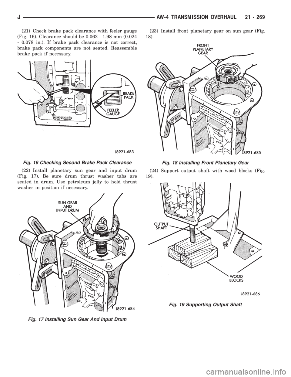
(21) Check brake pack clearance with feeler gauge
(Fig. 16). Clearance should be 0.062 - 1.98 mm (0.024
- 0.078 in.). If brake pack clearance is not correct,
brake pack components are not seated. Reassemble
brake pack if necessary.
(22) Install planetary sun gear and input drum
(Fig. 17). Be sure drum thrust washer tabs are
seated in drum. Use petroleum jelly to hold thrust
washer in position if necessary.(23) Install front planetary gear on sun gear (Fig.
18).
(24) Support output shaft with wood blocks (Fig.
19).
Fig. 16 Checking Second Brake Pack Clearance
Fig. 17 Installing Sun Gear And Input Drum
Fig. 18 Installing Front Planetary Gear
Fig. 19 Supporting Output Shaft
JAW-4 TRANSMISSION OVERHAUL 21 - 269
Page 1647 of 2198
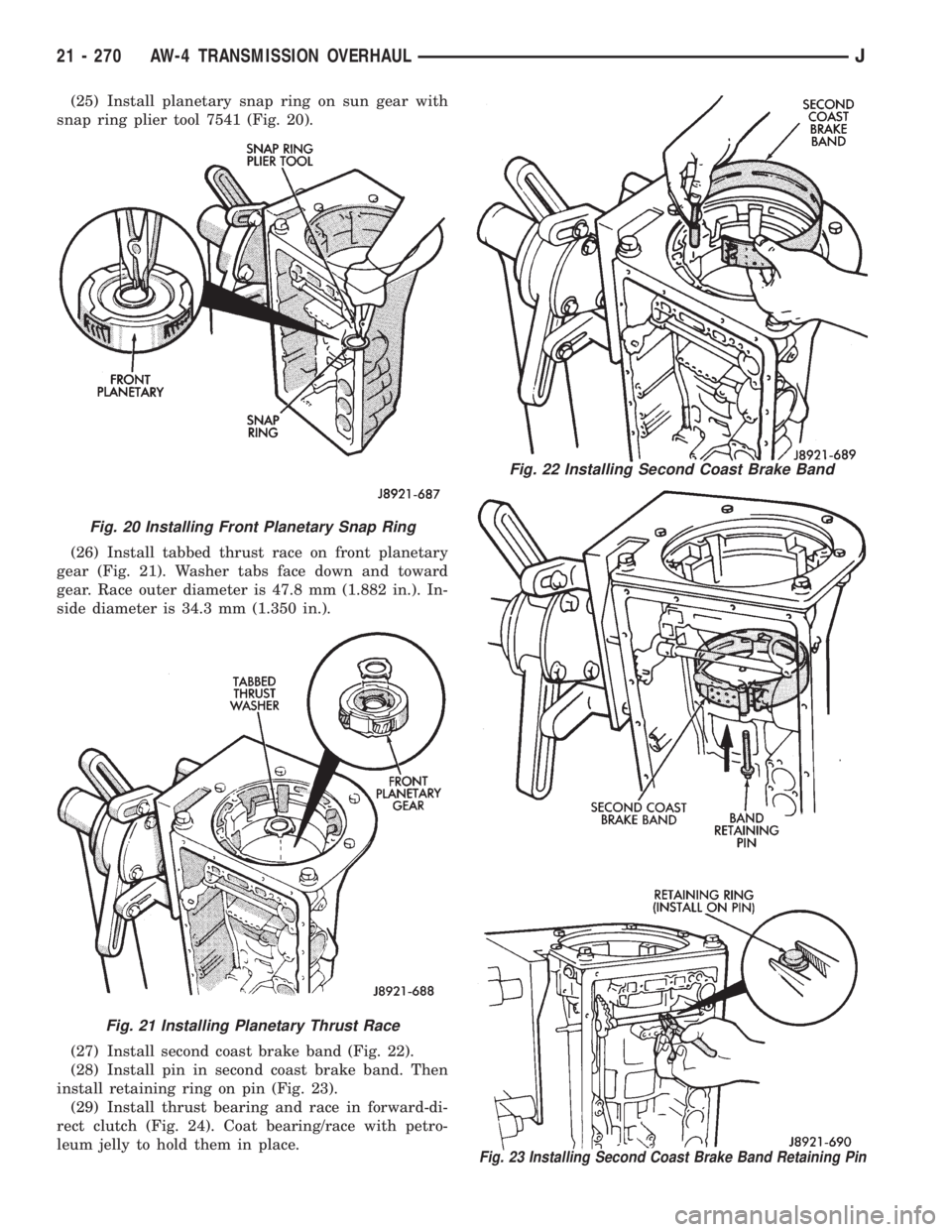
(25) Install planetary snap ring on sun gear with
snap ring plier tool 7541 (Fig. 20).
(26) Install tabbed thrust race on front planetary
gear (Fig. 21). Washer tabs face down and toward
gear. Race outer diameter is 47.8 mm (1.882 in.). In-
side diameter is 34.3 mm (1.350 in.).
(27) Install second coast brake band (Fig. 22).
(28) Install pin in second coast brake band. Then
install retaining ring on pin (Fig. 23).
(29) Install thrust bearing and race in forward-di-
rect clutch (Fig. 24). Coat bearing/race with petro-
leum jelly to hold them in place.
Fig. 22 Installing Second Coast Brake Band
Fig. 23 Installing Second Coast Brake Band Retaining Pin
Fig. 20 Installing Front Planetary Snap Ring
Fig. 21 Installing Planetary Thrust Race
21 - 270 AW-4 TRANSMISSION OVERHAULJ
Page 1648 of 2198
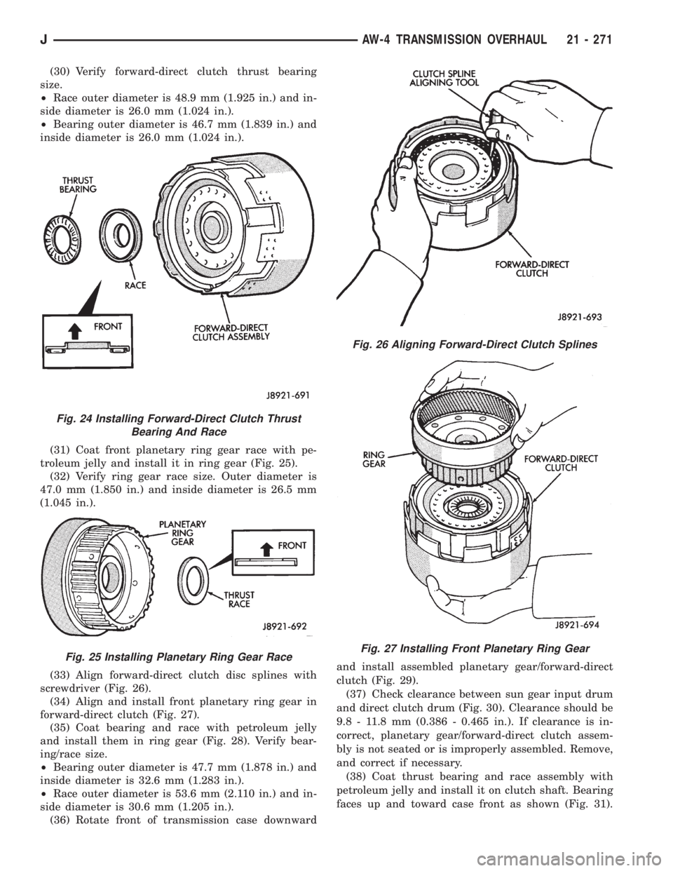
(30) Verify forward-direct clutch thrust bearing
size.
²Race outer diameter is 48.9 mm (1.925 in.) and in-
side diameter is 26.0 mm (1.024 in.).
²Bearing outer diameter is 46.7 mm (1.839 in.) and
inside diameter is 26.0 mm (1.024 in.).
(31) Coat front planetary ring gear race with pe-
troleum jelly and install it in ring gear (Fig. 25).
(32) Verify ring gear race size. Outer diameter is
47.0 mm (1.850 in.) and inside diameter is 26.5 mm
(1.045 in.).
(33) Align forward-direct clutch disc splines with
screwdriver (Fig. 26).
(34) Align and install front planetary ring gear in
forward-direct clutch (Fig. 27).
(35) Coat bearing and race with petroleum jelly
and install them in ring gear (Fig. 28). Verify bear-
ing/race size.
²Bearing outer diameter is 47.7 mm (1.878 in.) and
inside diameter is 32.6 mm (1.283 in.).
²Race outer diameter is 53.6 mm (2.110 in.) and in-
side diameter is 30.6 mm (1.205 in.).
(36) Rotate front of transmission case downwardand install assembled planetary gear/forward-direct
clutch (Fig. 29).
(37) Check clearance between sun gear input drum
and direct clutch drum (Fig. 30). Clearance should be
9.8 - 11.8 mm (0.386 - 0.465 in.). If clearance is in-
correct, planetary gear/forward-direct clutch assem-
bly is not seated or is improperly assembled. Remove,
and correct if necessary.
(38) Coat thrust bearing and race assembly with
petroleum jelly and install it on clutch shaft. Bearing
faces up and toward case front as shown (Fig. 31).
Fig. 24 Installing Forward-Direct Clutch Thrust
Bearing And Race
Fig. 25 Installing Planetary Ring Gear Race
Fig. 26 Aligning Forward-Direct Clutch Splines
Fig. 27 Installing Front Planetary Ring Gear
JAW-4 TRANSMISSION OVERHAUL 21 - 271
Page 1649 of 2198
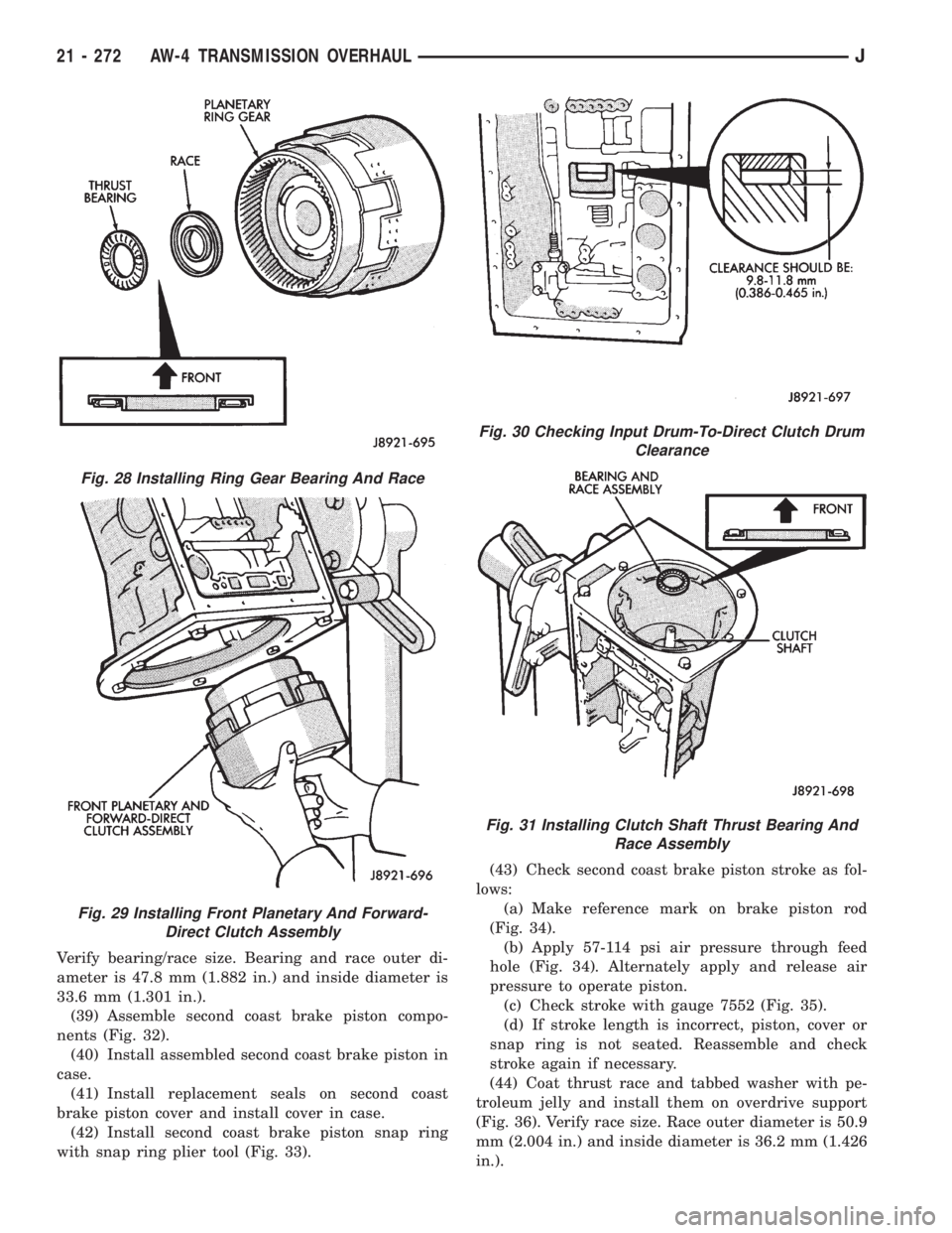
Verify bearing/race size. Bearing and race outer di-
ameter is 47.8 mm (1.882 in.) and inside diameter is
33.6 mm (1.301 in.).
(39) Assemble second coast brake piston compo-
nents (Fig. 32).
(40) Install assembled second coast brake piston in
case.
(41) Install replacement seals on second coast
brake piston cover and install cover in case.
(42) Install second coast brake piston snap ring
with snap ring plier tool (Fig. 33).(43) Check second coast brake piston stroke as fol-
lows:
(a) Make reference mark on brake piston rod
(Fig. 34).
(b) Apply 57-114 psi air pressure through feed
hole (Fig. 34). Alternately apply and release air
pressure to operate piston.
(c) Check stroke with gauge 7552 (Fig. 35).
(d) If stroke length is incorrect, piston, cover or
snap ring is not seated. Reassemble and check
stroke again if necessary.
(44) Coat thrust race and tabbed washer with pe-
troleum jelly and install them on overdrive support
(Fig. 36). Verify race size. Race outer diameter is 50.9
mm (2.004 in.) and inside diameter is 36.2 mm (1.426
in.).
Fig. 28 Installing Ring Gear Bearing And Race
Fig. 29 Installing Front Planetary And Forward-
Direct Clutch Assembly
Fig. 30 Checking Input Drum-To-Direct Clutch Drum
Clearance
Fig. 31 Installing Clutch Shaft Thrust Bearing And
Race Assembly
21 - 272 AW-4 TRANSMISSION OVERHAULJ
Page 1650 of 2198
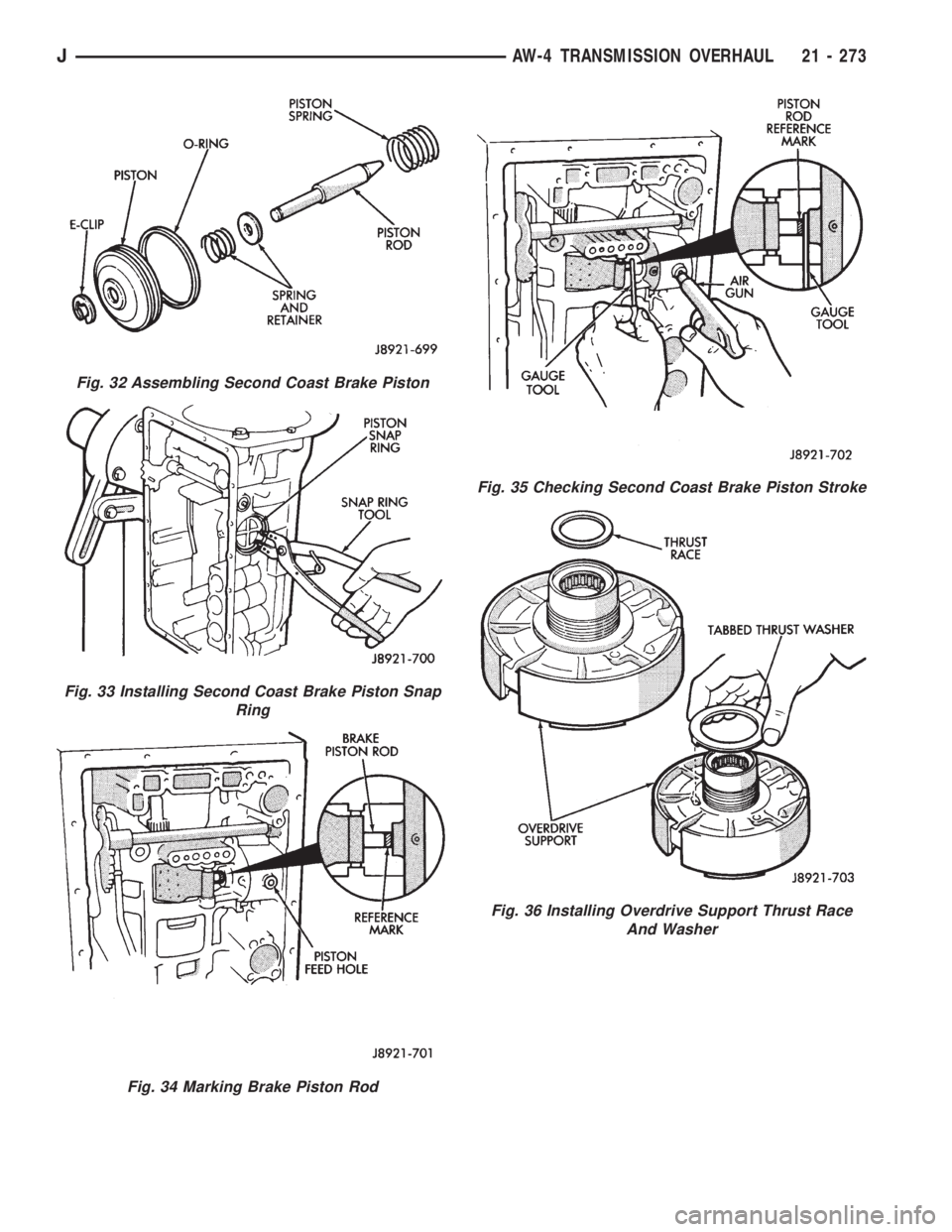
Fig. 32 Assembling Second Coast Brake Piston
Fig. 33 Installing Second Coast Brake Piston Snap
Ring
Fig. 34 Marking Brake Piston Rod
Fig. 35 Checking Second Coast Brake Piston Stroke
Fig. 36 Installing Overdrive Support Thrust Race
And Washer
JAW-4 TRANSMISSION OVERHAUL 21 - 273