torque JEEP CHEROKEE 2016 KL / 5.G User Guide
[x] Cancel search | Manufacturer: JEEP, Model Year: 2016, Model line: CHEROKEE, Model: JEEP CHEROKEE 2016 KL / 5.GPages: 236, PDF Size: 11.24 MB
Page 66 of 236

LANESENSE
The LaneSense system can be enabled and disabled with the LaneSense button
located on the switch panel below the Uconnect display.
• Push the LaneSense button to turn the system ON (LED turns off).
The LaneSense system is operational at speeds above 37 mph (60 km/h) and below
112 mph (180 km/h). The LaneSense system uses a forward looking camera to
detect lane markings and measure vehicle position within the lane boundaries.
When both lane markings are detected and the driver unintentionally drifts out of the
lane (no turn signal applied), the LaneSense system provides a haptic warning in the
form of torque applied to the steering wheel to prompt the driver to remain within the
lane boundaries. If the driver continues to unintentionally drift out of the lane, the
LaneSense system provides a visual warning through the Electronic Vehicle Informa-
tion Center (EVIC) or Driver Information Display (DID) to prompt the driver to remain
within the lane boundaries.
The driver may manually override the haptic warning by applying torque into the
steering wheel at any time.
When only a single lane marking is detected and the driver unintentionally drifts
across the lane marking (no turn signal applied), the LaneSense system provides a
visual warning through the Electronic Vehicle Information Center (EVIC) or Driver
Information Display (DID) to prompt the driver to remain within the lane. When only
a single lane marking is detected, a haptic (torque) warning will not be provided.
Refer to your Owner's Manual on the DVD for further details.
NOTE:
When operating conditions have been met, the LaneSense system will monitor if the
driver’s hands are on the steering wheel and provides an audible warning to the driver
when the driver’s hands are not detected on the steering wheel. The system will
cancel if the driver does not return their hands to the wheel.
PARKVIEW REAR BACK UP CAMERA
Your vehicle may be equipped with the ParkView Rear Back Up Camera that allows
you to see an on-screen image of the rear surroundings of your vehicle whenever the
shift lever is put into REVERSE. The image will be displayed in the touchscreen
display along with a caution note to “check entire surroundings” across the top of the
screen. After five seconds this note will disappear. The ParkView camera is located on
the rear of the vehicle above the rear License plate.
OPERATING YOUR VEHICLE
64
Page 155 of 236

FOUR-WHEEL DRIVE OPERATION
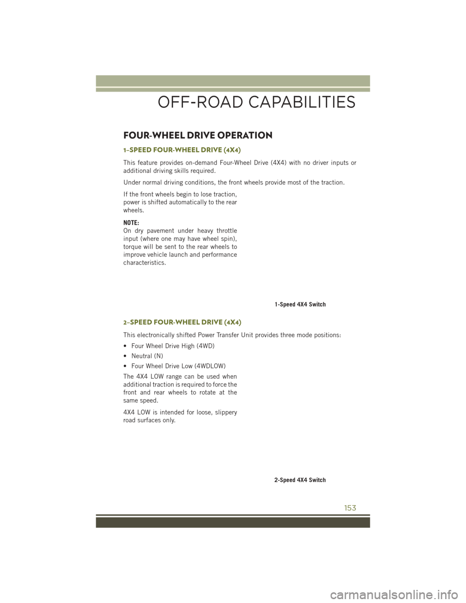
1–SPEED FOUR-WHEEL DRIVE (4X4)
This feature provides on-demand Four-Wheel Drive (4X4) with no driver inputs or
additional driving skills required.
Under normal driving conditions, the front wheels provide most of the traction.
If the front wheels begin to lose traction,
power is shifted automatically to the rear
wheels.
NOTE:
On dry pavement under heavy throttle
input (where one may have wheel spin),
torque will be sent to the rear wheels to
improve vehicle launch and performance
characteristics.
2–SPEED FOUR-WHEEL DRIVE (4X4)
This electronically shifted Power Transfer Unit provides three mode positions:
• Four Wheel Drive High (4WD)
• Neutral (N)
• Four Wheel Drive Low (4WDLOW)
The 4X4 LOW range can be used when
additional traction is required to force the
front and rear wheels to rotate at the
same speed.
4X4 LOW is intended for loose, slippery
road surfaces only.
1-Speed 4X4 Switch
2-Speed 4X4 Switch
OFF-ROAD CAPABILITIES
153
Page 187 of 236

8. Mount the spare tire.
CAUTION!
Be sure to mount the spare tire with the valve stem facing outward. The vehicle
could be damaged if the spare tire is mounted incorrectly.
NOTE: • For vehicles so equipped, do not attempt to install a center cap or wheel coveron the compact spare.
• Refer to “Compact Spare Tire” and to “Limited-Use Spare” under “Tires— General Information” in “Starting and Operating” in the Owner's Manual on the
DVD for additional warnings, cautions, and information about the spare tire, its
use, and operation.
9. Install the wheel bolts with the threaded end of the wheel bolt toward the wheel. Lightly tighten the wheel bolts.
WARNING!
To avoid the risk of forcing the vehicle off the jack, do not fully tighten the wheel
bolts until the vehicle has been lowered. Failure to follow this warning may result
in serious injury.
10. Lower the vehicle to the ground by turning the jack handle counterclockwise.
11. Finish tightening the lug bolts. Push down on the wrench while at the end of the handle for increased leverage. Tighten the lug bolts in a star pattern until each
nut has been tightened twice. The correct wheel bolt tightness is 100 ft lb
(135 N·m). If in doubt about the correct tightness, have them checked with a
torque wrench by your authorized dealer or at a service station.
12. Securely stow the jack, tools, chocks and flat tire.
WARNING!
A loose tire or jack thrown forward in a collision or hard stop could endanger the
occupants of the vehicle. Always stow the jack parts and the spare tire in the
places provided. Have the deflated (flat) tire repaired or replaced immediately.
WHAT TO DO IN EMERGENCIES
185
Page 188 of 236

Road Tire Installation
1. Mount the road tire on the axle.
2. Install the remaining wheel bolts with the threaded end of the wheel bolt towardthe wheel. Lightly tighten the wheel bolts.
WARNING!
To avoid the risk of forcing the vehicle off the jack, do not tighten the lug nuts fully
until the vehicle has been lowered. Failure to follow this warning may result in
serious injury.
3. Lower the vehicle to the ground by turning the jack handle counterclockwise.
4. Finish tightening the lug bolts. Push down on the wrench while at the end of the handle for increased leverage. Tighten the lug bolts in a star pattern until each nut
has been tightened twice. The correct wheel bolt tightness is 100 ft lb (135 N·m).
If in doubt about the correct tightness, have them checked with a torque wrench
by your authorized dealer or at a service station.
5. Lower the jack until it is free. Remove the wheel chocks. Reassemble the lug wrench to the jack assembly and stow it in the spare tire area. Secure the
assembly using the means provided. Release the parking brake before driving the
vehicle.
6. After 25 miles (40 km) check the wheel bolt torque with a torque wrench to ensure that all wheel bolts are properly seated against the wheel.
JUMP-STARTING PROCEDURES
If your vehicle has a discharged battery it can be jump-started using a set of jumper
cables and a battery in another vehicle or by using a portable battery booster pack.
Jump-starting can be dangerous if done improperly so please follow the procedures
in this section carefully.
NOTE:
When using a portable battery booster pack follow the manufacturer’s operating
instructions and precautions.
CAUTION!
Do not use a portable battery booster pack or any other booster source with a
system voltage greater than 12 Volts or damage to the battery, starter motor,
alternator or electrical system may occur.
WARNING!
Do not attempt jump-starting if the battery is frozen. It could rupture or explode
and cause personal injury.
WHAT TO DO IN EMERGENCIES
186