display JEEP CHEROKEE 2019 Owner handbook (in English)
[x] Cancel search | Manufacturer: JEEP, Model Year: 2019, Model line: CHEROKEE, Model: JEEP CHEROKEE 2019Pages: 344, PDF Size: 6.35 MB
Page 44 of 344
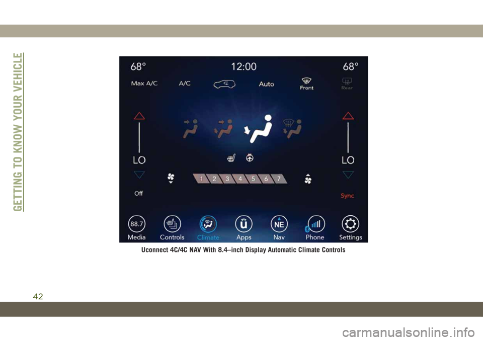
Uconnect 4C/4C NAV With 8.4–inch Display Automatic Climate Controls
GETTING TO KNOW YOUR VEHICLE
42
Page 47 of 344
Icon Description
REAR
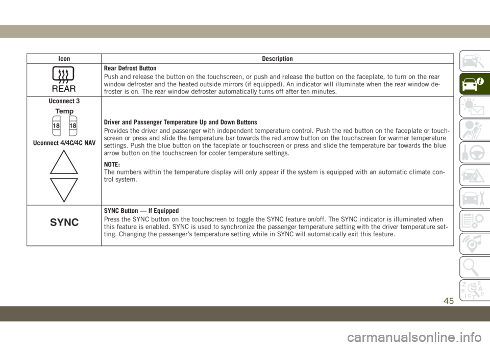
Rear Defrost Button
Push and release the button on the touchscreen, or push and release the button on the faceplate, to turn on the rear
window defroster and the heated outside mirrors (if equipped). An indicator will illuminate when the rear window de-
froster is on. The rear window defroster automatically turns off after ten minutes.
Uconnect 3
Uconnect 4/4C/4C NAV
Driver and Passenger Temperature Up and Down Buttons
Provides the driver and passenger with independent temperature control. Push the red button on the faceplate or touch-
screen or press and slide the temperature bar towards the red arrow button on the touchscreen for warmer temperature
settings. Push the blue button on the faceplate or touchscreen or press and slide the temperature bar towards the blue
arrow button on the touchscreen for cooler temperature settings.
NOTE:
The numbers within the temperature display will only appear if the system is equipped with an automatic climate con-
trol system.
SYNC Button — If Equipped
Press the SYNC button on the touchscreen to toggle the SYNC feature on/off. The SYNC indicator is illuminated when
this feature is enabled. SYNC is used to synchronize the passenger temperature setting with the driver temperature set-
ting. Changing the passenger’s temperature setting while in SYNC will automatically exit this feature.
45
Page 50 of 344
(button on the touchscreen greyed out) if
conditions exist that could create fogging on
the inside of the windshield.
Automatic Temperature Control (ATC) —
If Equipped
Automatic Operation
1. Push the AUTO button on the faceplate,
or the AUTO button on the touchscreen on
the Automatic Temperature Control (ATC)
Panel.
2. Next, adjust the temperature you would
like the system to maintain by adjusting
the driver and passenger temperature
control buttons. Once the desired tem-
perature is displayed, the system will
achieve and automatically maintain that
comfort level.
3. When the system is set up for your comfort
level, it is not necessary to change the
settings. You will experience the greatest
efficiency by simply allowing the system
to function automatically.NOTE:
• It is not necessary to move the temperature
settings for cold or hot vehicles. The system
automatically adjusts the temperature,
mode, and blower speed to provide comfort
as quickly as possible.
• The temperature can be displayed in U.S.
or Metric units by selecting the US/Metric
customer-programmable feature. Refer to
the “Uconnect Settings” in “Multimedia”
in your Owner’s Manual for further
information.
To provide you with maximum comfort in the
Automatic mode during cold start-ups, the
blower fan will remain on low until the engine
warms up. The blower will increase in speed
and transition into Auto mode.
Manual Operation Override
This system offers a full complement of
manual override features. The AUTO symbol
in the front ATC display will be turned off
when the system is being used in the manual
mode.
Operating Tips
Summer Operation
The engine cooling system must be protected
with a high-quality antifreeze coolant to pro-
vide proper corrosion protection and to pro-
tect against engine overheating. OAT coolant
(conforming to MS.90032) is recommended.
Winter Operation
To ensure the best possible heater and de-
froster performance, make sure the engine
cooling system is functioning properly and
the proper amount, type, and concentration
of coolant is used. Use of the Air Recircula-
tion mode during Winter months is not rec-
ommended, because it may cause window
fogging.
Vacation/Storage
Before you store your vehicle, or keep it out of
service (i.e., vacation) for two weeks or more,
run the air conditioning system at idle for
about five minutes, in fresh air with the
blower setting on high. This will ensure ad-
GETTING TO KNOW YOUR VEHICLE
48
Page 64 of 344
INSTRUMENT CLUSTER
DISPLAY
Your vehicle may be equipped with an instru-
ment cluster display, which offers useful in-
formation to the driver. With the ignition in
the STOP/OFF mode, opening/closing of a
door will activate the display for viewing, and
display the total miles, or kilometers, in the
odometer. Your instrument cluster display is
designed to display important information
about your vehicle’s systems and features.
Using a driver interactive display located on
the instrument panel, your instrument clus-
ter display can show you how systems are
working and give you warnings when they
aren’t. The steering wheel mounted controls
allow you to scroll through and enter the main
menus and submenus. You can access the
specific information you want and make se-
lections and adjustments.
Instrument Cluster Display Location And
Controls
The instrument cluster display features a
driver-interactive display that is located in
the instrument cluster.
The instrument cluster display menu items
consist of the following:
• Speedometer
• Vehicle Info
• Driver Assist — If Equipped
• Fuel Economy
• Trip Info
• Stop/Start
• Audio
• Messages
• Screen Setup
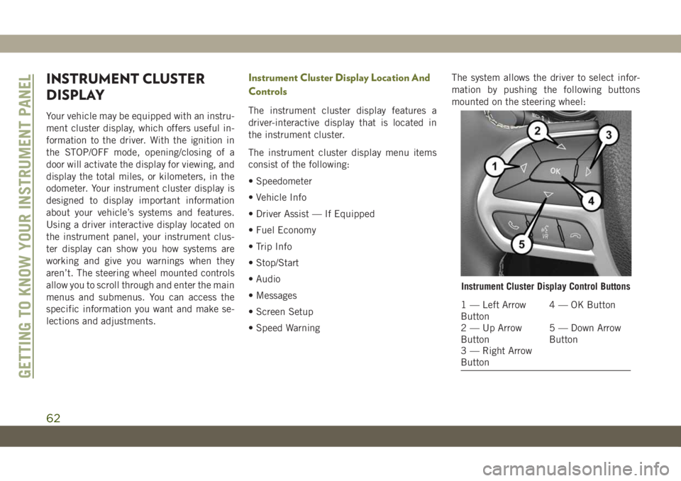
• Speed WarningThe system allows the driver to select infor-
mation by pushing the following buttons
mounted on the steering wheel:
Instrument Cluster Display Control Buttons
1 — Left Arrow
Button4 — OK Button
2 — Up Arrow
Button5 — Down Arrow
Button
3 — Right Arrow
Button
GETTING TO KNOW YOUR INSTRUMENT PANEL
62
Page 65 of 344
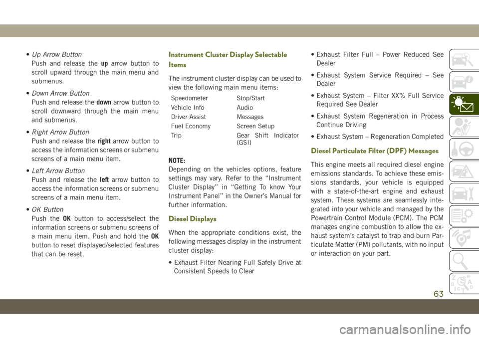
•Up Arrow Button
Push and release theuparrow button to
scroll upward through the main menu and
submenus.
•Down Arrow Button
Push and release thedownarrow button to
scroll downward through the main menu
and submenus.
•Right Arrow Button
Push and release therightarrow button to
access the information screens or submenu
screens of a main menu item.
•Left Arrow Button
Push and release theleftarrow button to
access the information screens or submenu
screens of a main menu item.
•OK Button
Push theOKbutton to access/select the
information screens or submenu screens of
a main menu item. Push and hold theOK
button to reset displayed/selected features
that can be reset.Instrument Cluster Display Selectable
Items
The instrument cluster display can be used to
view the following main menu items:
Speedometer Stop/Start
Vehicle Info Audio
Driver Assist Messages
Fuel Economy Screen Setup
Trip Gear Shift Indicator
(GSI)
NOTE:
Depending on the vehicles options, feature
settings may vary. Refer to the “Instrument
Cluster Display” in “Getting To know Your
Instrument Panel” in the Owner’s Manual for
further information.
Diesel Displays
When the appropriate conditions exist, the
following messages display in the instrument
cluster display:
• Exhaust Filter Nearing Full Safely Drive at
Consistent Speeds to Clear• Exhaust Filter Full – Power Reduced See
Dealer
• Exhaust System Service Required – See
Dealer
• Exhaust System – Filter XX% Full Service
Required See Dealer
• Exhaust System Regeneration in Process
Continue Driving
• Exhaust System – Regeneration Completed
Diesel Particulate Filter (DPF) Messages
This engine meets all required diesel engine
emissions standards. To achieve these emis-
sions standards, your vehicle is equipped
with a state-of-the-art engine and exhaust
system. These systems are seamlessly inte-
grated into your vehicle and managed by the
Powertrain Control Module (PCM). The PCM
manages engine combustion to allow the ex-
haust system’s catalyst to trap and burn Par-
ticulate Matter (PM) pollutants, with no input
or interaction on your part.
63
Page 66 of 344
WARNING!
A hot exhaust system can start a fire if you
park over materials that can burn. Such
materials might be grass or leaves coming
into contact with your exhaust system. Do
not park or operate your vehicle in areas
where your exhaust system can contact
anything that can burn.
CAUTION!
The engine may be switched off even if the
warning light is on: repeated interruptions
of the regeneration process could cause an
early deterioration of engine oil. For this
reason it is always advisable to wait for the
symbol to go off before turning off the
engine, following the instructions above.
Do not complete the DPF regeneration
process when the vehicle is stopped.
WARNING LIGHTS AND
MESSAGES
The warning/indicator lights will illuminate in
the instrument panel together with a dedi-
cated message and/or acoustic signal when
applicable. These indications are indicative
and precautionary and as such must not be
considered as exhaustive and/or alternative
to the information contained in the Owner’s
Manual, which you are advised to read care-
fully in all cases. Always refer to the informa-
tion in this chapter in the event of a failure
indication. All active telltales will display first
if applicable. The system check menu may
appear different based upon equipment op-
tions and current vehicle status. Some tell-
tales are optional and may not appear.
Red Warning Lights
— Seat Belt Reminder Warning Light
This warning light indicates when the driver
or passenger seat belt is unbuckled. When
the ignition is first placed in the ON/RUN or
ACC/ON/RUN position and if the driver’s seat
belt is unbuckled, a chime will sound and the
light will turn on. When driving, if the driver
or front passenger seat belt remains unbuck-
led, the Seat Belt Reminder Light will flash or
remain on continuously and a chime will
sound.
Refer to “Occupant Restraint Systems” in
“Safety” for further information.
— Air Bag Warning Light
This warning light will illuminate to indicate
a fault with the air bag, and will turn on for
four to eight seconds as a bulb check when
the ignition is placed in the ON/RUN or
ACC/ON/RUN position. This light will illumi-
nate with a single chime when a fault with the
air bag has been detected, it will stay on until
the fault is cleared. If the light is either not on
GETTING TO KNOW YOUR INSTRUMENT PANEL
64
Page 72 of 344
CAUTION!
could affect fuel economy and driveability.
If the MIL is flashing, severe catalytic
converter damage and power loss will soon
occur. Immediate service is required.
— Adblue (UREA) Injection System
Failure Warning Light — If Equipped
This warning light will illuminate along with a
dedicated message on the display (If
Equipped) if an unknown fluid not conform-
ing with acceptable characteristics is in-
serted, or if an average consumption of Ad-
blue (UREA) over 50% is detected. Contact
an authorized dealer as soon as possible.
If the problem is not solved, a specific mes-
sage will appear on the Instrument Cluster
Display whenever a certain threshold is
reached until it will no longer be possible to
start the engine.When about 125 mi (200 km) are remaining
before the Adblue (UREA) tank is empty, a
continuous dedicated message will appear on
the instrument panel, accompanied by a
buzzer sound (If Equipped).
SERV4WD— Service 4WD Warning Light — If
Equipped
This warning light will illuminate to signal a
fault with the 4WD system. If the light stays
on or comes on during driving, it means that
the 4WD system is not functioning properly
and that service is required. We recommend
you drive to the nearest service center and
have the vehicle serviced immediately.
— Service Forward Collision Warn-
ing (FCW) Light — If Equipped
This telltale will turn on to indicate a fault in
the Forward Collision Warning System. Con-
tact your local authorized dealer for service.
Refer to "Forward Collision Warning (FCW)" in
"Safety" for further information.
— Service Stop/Start System Warning
Light
This telltale will turn on to indicate the Stop/
Start system is not functioning properly and
service is required. Contact an authorized
dealer for service.
— Speed Control Fault Warning Light
This warning light will illuminate to indicate
the Speed Control System is not functioning
properly and service is required. Contact an
authorized dealer.
— Tire Pressure Monitoring System
(TPMS) Warning Light
The warning light switches on and a message
is displayed to indicate that the tire pressure
is lower than the recommended value and/or
that slow pressure loss is occurring. In these
cases, optimal tire duration and fuel con-
sumption may not be guaranteed.
Should one or more tires be in the condition
mentioned above, the display will show the
indications corresponding to each tire.
GETTING TO KNOW YOUR INSTRUMENT PANEL
70
Page 74 of 344
CAUTION!
your authorized dealer to have your sensor
function checked.
Yellow Indicator Lights
— Active Speed Limiter Fault Indica-
tor Light — If Equipped
This warning light will illuminate to signal
when there is a fault detected with the Active
Speed Limiter.
— Forward Collision Warning Off Indi-
cator Light — If Equipped
This light indicates that Forward Collision
Warning is off.
— 4WD Low Indicator Light — If
Equipped
This light alerts the driver that the vehicle is
in the four-wheel drive LOW mode. The front
and rear driveshafts are mechanically locked
together forcing the front and rear wheels to
rotate at the same speed. Low range provides
a greater gear reduction ratio to provide in-
creased torque at the wheels.Refer to “Four-Wheel Drive Operation — If
Equipped” in “Starting And Operating” for
further information on four-wheel drive op-
eration and proper use.
— Rear Axle Lock Indicator Light
This light indicates when the rear axle lock
has been activated.
— Rear Fog Indicator — If Equipped
This indicator light will illuminate when the
rear fog lights are on.
— Glow Plug Light — If Equipped
This vehicle will inhibit engine cranking
when the ambient temperature is less than
–22° F (–30° C) and the oil temperature
sensor reading indicates an engine block
heater has not been used. The Glow Plug
light will flash during in cold weather for up
to ten seconds.
If equipped with a block heater harness the
message "Plug In Engine Heater", will be
displayed in the instrument cluster when theambient temperature is below 5°F (-15° C) at
the time the engine is shut off as a reminder
to avoid possible crank delays at the next cold
start.
— Low Diesel Exhaust Emissions Addi-
tive (UREA) Indicator Light — If Equipped
The Low Diesel Exhaust Emissions Additive
(UREA) indicator light illuminates when the
UREA level is low.
Fill the UREA tank as soon as possible with at
least 1.3 gallons (5 liters) of UREA.
If filling the tank is done with a remaining
range of UREA in the tank equal to zero, you
may need to wait 2 minutes before starting
the vehicle.
Refer to “Starting And Operating” for further
information.
— Water In Fuel Indicator Light — If
Equipped
The “Water In Fuel Indicator Light” will illu-
minate when there is water detected in the
fuel filter. If this light remains on, DO NOT
GETTING TO KNOW YOUR INSTRUMENT PANEL
72
Page 75 of 344
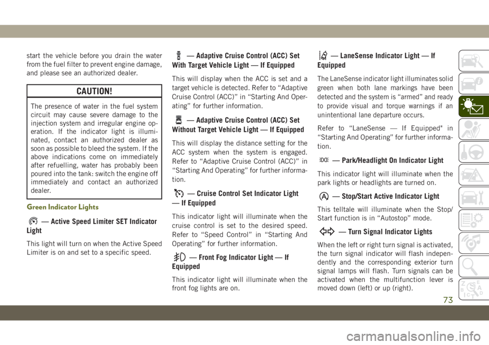
start the vehicle before you drain the water
from the fuel filter to prevent engine damage,
and please see an authorized dealer.
CAUTION!
The presence of water in the fuel system
circuit may cause severe damage to the
injection system and irregular engine op-
eration. If the indicator light is illumi-
nated, contact an authorized dealer as
soon as possible to bleed the system. If the
above indications come on immediately
after refuelling, water has probably been
poured into the tank: switch the engine off
immediately and contact an authorized
dealer.
Green Indicator Lights
— Active Speed Limiter SET Indicator
Light
This light will turn on when the Active Speed
Limiter is on and set to a specific speed.
— Adaptive Cruise Control (ACC) Set
With Target Vehicle Light — If Equipped
This will display when the ACC is set and a
target vehicle is detected. Refer to “Adaptive
Cruise Control (ACC)” in “Starting And Oper-
ating” for further information.
— Adaptive Cruise Control (ACC) Set
Without Target Vehicle Light — If Equipped
This will display the distance setting for the
ACC system when the system is engaged.
Refer to “Adaptive Cruise Control (ACC)” in
“Starting And Operating” for further informa-
tion.
— Cruise Control Set Indicator Light
— If Equipped
This indicator light will illuminate when the
cruise control is set to the desired speed.
Refer to “Speed Control” in “Starting And
Operating” for further information.
— Front Fog Indicator Light — If
Equipped
This indicator light will illuminate when the
front fog lights are on.
— LaneSense Indicator Light — If
Equipped
The LaneSense indicator light illuminates solid
green when both lane markings have been
detected and the system is “armed” and ready
to provide visual and torque warnings if an
unintentional lane departure occurs.
Refer to “LaneSense — If Equipped" in
“Starting And Operating” for further informa-
tion.
— Park/Headlight On Indicator Light
This indicator light will illuminate when the
park lights or headlights are turned on.
— Stop/Start Active Indicator Light
This telltale will illuminate when the Stop/
Start function is in “Autostop” mode.
— Turn Signal Indicator Lights
When the left or right turn signal is activated,
the turn signal indicator will flash indepen-
dently and the corresponding exterior turn
signal lamps will flash. Turn signals can be
activated when the multifunction lever is
moved down (left) or up (right).
73
Page 77 of 344
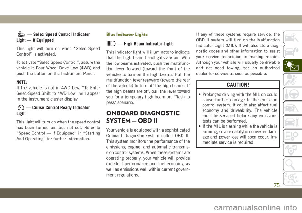
— Selec Speed Control Indicator
Light — If Equipped
This light will turn on when “Selec Speed
Control” is activated.
To activate “Selec Speed Control”, assure the
vehicle is Four Wheel Drive Low (4WD) and
push the button on the Instrument Panel.
NOTE:
If the vehicle is not in 4WD Low, “To Enter
Selec-Speed Shift to 4WD Low” will appear
in the instrument cluster display.
— Cruise Control Ready Indicator
Light
This light will turn on when the speed control
has been turned on, but not set. Refer to
“Speed Control — If Equipped” in “Starting
And Operating” for further information.
Blue Indicator Lights
— High Beam Indicator Light
This indicator light will illuminate to indicate
that the high beam headlights are on. With
the low beams activated, push the multifunc-
tion lever forward (toward the front of the
vehicle) to turn on the high beams. Pull the
multifunction lever rearward (toward the rear
of the vehicle) to turn off the high beams. If
the high beams are off, pull the lever toward
you for a temporary high beam on, "flash to
pass" scenario.
ONBOARD DIAGNOSTIC
SYSTEM — OBD II
Your vehicle is equipped with a sophisticated
Onboard Diagnostic system called OBD II.
This system monitors the performance of the
emissions, engine, and automatic transmis-
sion control systems. When these systems are
operating properly, your vehicle will provide
excellent performance and fuel economy, as
well as emissions well within current govern-
ment regulations.If any of these systems require service, the
OBD II system will turn on the Malfunction
Indicator Light (MIL). It will also store diag-
nostic codes and other information to assist
your service technician in making repairs.
Although your vehicle will usually be drivable
and not need towing, see an authorized
dealer for service as soon as possible.
CAUTION!
• Prolonged driving with the MIL on could
cause further damage to the emission
control system. It could also affect fuel
economy and driveability. The vehicle
must be serviced before any emissions
tests can be performed.
• If the MIL is flashing while the vehicle is
running, severe catalytic converter dam-
age and power loss will soon occur. Im-
mediate service is required.
75