JEEP CHEROKEE 2023 Owners Manual
Manufacturer: JEEP, Model Year: 2023, Model line: CHEROKEE, Model: JEEP CHEROKEE 2023Pages: 276, PDF Size: 12.55 MB
Page 141 of 276
MULTIMEDIA139
System Information
Clear Personal Data/Restore Settings
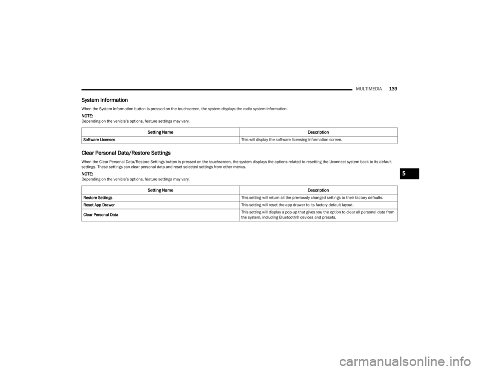
When the System Information button is pressed on the touchscreen, the system displays the radio system information.
NOTE:Depending on the vehicle’s options, feature settings may vary.
Setting Name Description
Software Licenses This will display the software licensing information screen.
When the Clear Personal Data/Restore Settings button is pressed on the touchscreen, the system displays the options related to resetting the Uconnect system back to its default
settings. These settings can clear personal data and reset selected settings from other menus.
NOTE:Depending on the vehicle’s options, feature settings may vary.
Setting NameDescription
Restore Settings This setting will return all the previously changed settings to their factory defaults.
Reset App Drawer This setting will reset the app drawer to its factory default layout.
Clear Personal Data This setting will display a pop-up that gives you the option to clear all personal data from
the system, including Bluetooth® devices and presets.
5
23_KL_OM_EN_USC_t.book Page 139
Page 142 of 276
140MULTIMEDIA
STEERING WHEEL AUDIO CONTROLS —
IF EQUIPPED
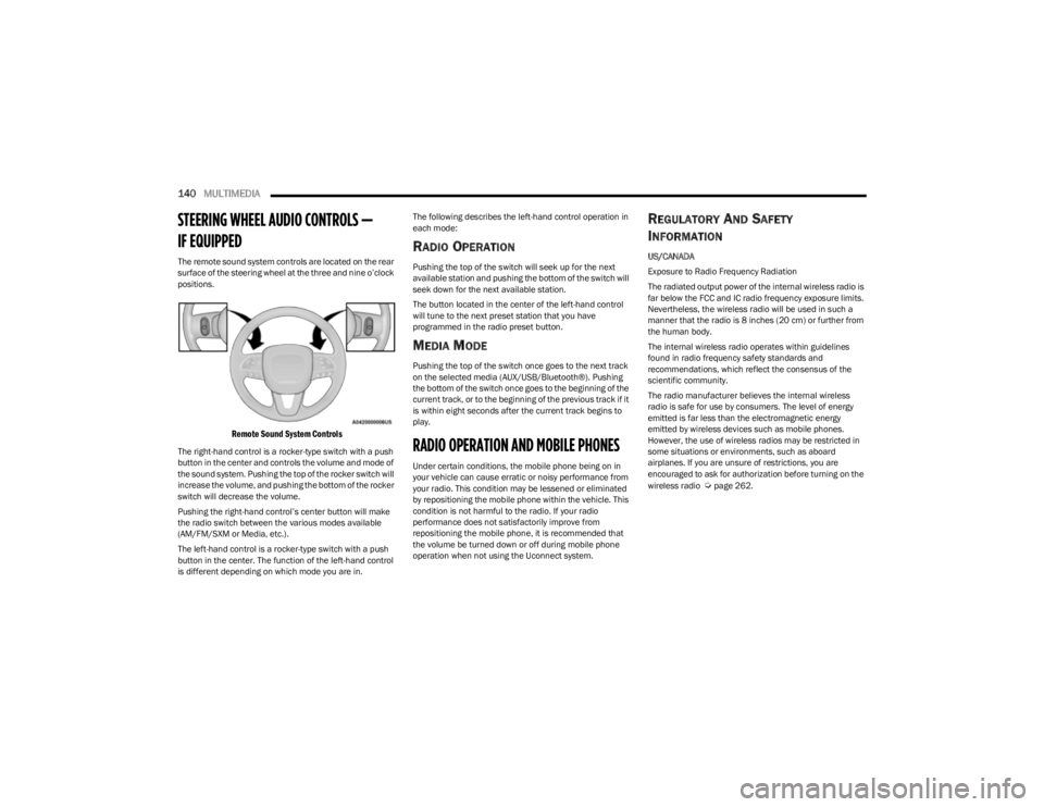
The remote sound system controls are located on the rear
surface of the steering wheel at the three and nine o’clock
positions.
Remote Sound System Controls
The right-hand control is a rocker-type switch with a push
button in the center and controls the volume and mode of
the sound system. Pushing the top of the rocker switch will
increase the volume, and pushing the bottom of the rocker
switch will decrease the volume.
Pushing the right-hand control’s center button will make
the radio switch between the various modes available
(AM/FM/SXM or Media, etc.).
The left-hand control is a rocker-type switch with a push
button in the center. The function of the left-hand control
is different depending on which mode you are in. The following describes the left-hand control operation in
each mode:
RADIO OPERATION
Pushing the top of the switch will seek up for the next
available station and pushing the bottom of the switch will
seek down for the next available station.
The button located in the center of the left-hand control
will tune to the next preset station that you have
programmed in the radio preset button.
MEDIA MODE
Pushing the top of the switch once goes to the next track
on the selected media (AUX/USB/Bluetooth®). Pushing
the bottom of the switch once goes to the beginning of the
current track, or to the beginning of the previous track if it
is within eight seconds after the current track begins to
play.
RADIO OPERATION AND MOBILE PHONES
Under certain conditions, the mobile phone being on in
your vehicle can cause erratic or noisy performance from
your radio. This condition may be lessened or eliminated
by repositioning the mobile phone within the vehicle. This
condition is not harmful to the radio. If your radio
performance does not satisfactorily improve from
repositioning the mobile phone, it is recommended that
the volume be turned down or off during mobile phone
operation when not using the Uconnect system.
REGULATORY AND SAFETY
I
NFORMATION
US/CANADA
Exposure to Radio Frequency Radiation
The radiated output power of the internal wireless radio is
far below the FCC and IC radio frequency exposure limits.
Nevertheless, the wireless radio will be used in such a
manner that the radio is 8 inches (20 cm) or further from
the human body.
The internal wireless radio operates within guidelines
found in radio frequency safety standards and
recommendations, which reflect the consensus of the
scientific community.
The radio manufacturer believes the internal wireless
radio is safe for use by consumers. The level of energy
emitted is far less than the electromagnetic energy
emitted by wireless devices such as mobile phones.
However, the use of wireless radios may be restricted in
some situations or environments, such as aboard
airplanes. If you are unsure of restrictions, you are
encouraged to ask for authorization before turning on the
wireless radio
Úpage 262.
23_KL_OM_EN_USC_t.book Page 140
Page 143 of 276
MULTIMEDIA141
OFF-ROAD PAGES — IF EQUIPPED
Your vehicle may be equipped with Off-Road Pages, which
displays vehicle information related to the drivetrain,
transfer case, and coolant/oil gauges.
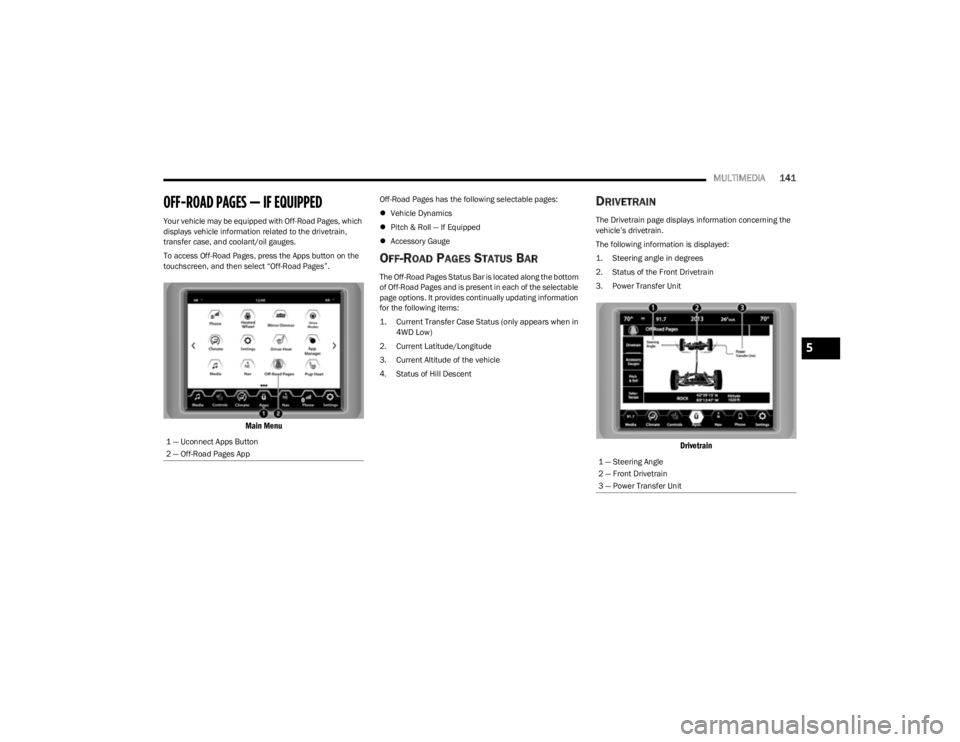
To access Off-Road Pages, press the Apps button on the
touchscreen, and then select “Off-Road Pages”.
Main Menu
Off-Road Pages has the following selectable pages:
Vehicle Dynamics
Pitch & Roll — If Equipped
Accessory Gauge
OFF-ROAD PAGES STATUS BAR
The Off-Road Pages Status Bar is located along the bottom
of Off-Road Pages and is present in each of the selectable
page options. It provides continually updating information
for the following items:
1. Current Transfer Case Status (only appears when in
4WD Low)
2. Current Latitude/Longitude
3. Current Altitude of the vehicle
4. Status of Hill Descent
DRIVETRAIN
The Drivetrain page displays information concerning the
vehicle’s drivetrain.
The following information is displayed:
1. Steering angle in degrees
2. Status of the Front Drivetrain
3. Power Transfer Unit
Drivetrain
1 — Uconnect Apps Button
2 — Off-Road Pages App
1 — Steering Angle
2 — Front Drivetrain
3 — Power Transfer Unit
5
23_KL_OM_EN_USC_t.book Page 141
Page 144 of 276

142MULTIMEDIA
PITCH & ROLL
The Pitch & Roll page displays the vehicle’s current pitch
(angle up and down) and roll (angle side to side) in
degrees. The Pitch & Roll gauges provide a visualization of
the current vehicle angle.
Pitch & Roll Menu
ACCESSORY GAUGES
The Accessory Gauges page displays the current status of
the vehicle’s Coolant Temperature, Oil Temperature,
Transmission Temperature, and Battery Voltage.
Accessory Gauges Menu
SELEC-TERRAIN — IF EQUIPPED
The Selec-Terrain page displays the current Selec-Terrain
mode through a high resolution image. The vehicle must
be in the ON/RUN position to display Selec-Terrain
information.
The selectable modes are as follows:
Auto — Default
Snow
Sand
Mud
Rock — Vehicle Must Be In 4WD Low
NOTE:While in the Selec-Terrain pages, the Off-Road Pages
Status Bar will also display the current Selec-Terrain
mode.
Current Selec-Terrain Mode
1 — Current Pitch
2 — Current Roll
23_KL_OM_EN_USC_t.book Page 142
Page 145 of 276
143
SAFETY
SAFETY FEATURES
ANTI-LOCK BRAKE SYSTEM (ABS)
The ABS provides increased vehicle stability and brake
performance under most braking conditions. The system
automatically prevents wheel lock and enhances vehicle
control during braking.
The ABS performs a self-check cycle to ensure that the
ABS is working properly each time the vehicle is started
and driven. During this self-check, you may hear a slight
clicking sound as well as some related motor noises.
The ABS is activated during braking when the system
detects one or more wheels are beginning to lock. Road
conditions such as ice, snow, gravel, bumps, railroad
tracks, loose debris, or panic stops may increase the
likelihood of ABS activation(s).
You also may experience the following normal
characteristics when the ABS activates:
ABS motor noise or clicking sounds (you may continue
to hear for a short time after the stop).
Brake pedal pulsations.
A slight drop of the brake pedal at the end of the stop.
The ABS is designed to function with the Original
Equipment Manufacturer (OEM) tires. Modification may
result in degraded ABS performance.
Anti-Lock Brake System (ABS) Warning
Light
The yellow ABS Warning Light will turn on when the ignition
is placed in the ON/RUN mode and may stay on for as long
as four seconds.
If the ABS Warning Light remains on or comes on while
driving, it indicates that the anti-lock portion of the brake
system is not functioning and that service is required.
However, the conventional brake system will continue to
operate normally if the ABS Warning Light is on.
If the ABS Warning Light is on, the brake system should be
serviced as soon as possible to restore the benefits of
Anti-Lock Brakes. If the ABS Warning Light does not come
on when the ignition is placed in the ON/RUN mode, have
the light repaired as soon as possible.
ELECTRONIC BRAKE CONTROL (EBC)
S
YSTEM
Your vehicle is equipped with an advanced EBC system.
This system includes Anti-Lock Brake System (ABS), Brake
Assist System (BAS), Electronic Brake Force Distribution
(EBD), Electronic Roll Mitigation (ERM), Electronic Stability
Control (ESC), Hill Start Assist (HSA), and Traction Control
System (TCS). These systems work together to enhance
both vehicle stability and control in various driving
conditions.
WARNING!
The ABS contains sophisticated electronic equip -
ment that may be susceptible to interference caused
by improperly installed or high output radio transmit -
ting equipment. This interference can cause possible
loss of anti-lock braking capability. Installation of
such equipment should be performed by qualified
professionals.
Pumping of the Anti-Lock Brakes will diminish their
effectiveness and may lead to a collision. Pumping
makes the stopping distance longer. Just press firmly
on your brake pedal when you need to slow down or
stop.
The ABS cannot prevent the natural laws of physics
from acting on the vehicle, nor can it increase
braking or steering efficiency beyond that afforded
by the condition of the vehicle brakes and tires or the
traction afforded.
The ABS cannot prevent collisions, including those
resulting from excessive speed in turns, following
another vehicle too closely, or hydroplaning.
The capabilities of an ABS equipped vehicle must
never be exploited in a reckless or dangerous
manner that could jeopardize the user’s safety or the
safety of others.
6
23_KL_OM_EN_USC_t.book Page 143
Page 146 of 276
144SAFETY
Your vehicle may also be equipped with Dynamic Steering
Torque (DST), Hill Descent Control (HDC), Rain Brake
Support (RBS), Ready Alert Braking (RAB), Selec-Speed
Control (SSC), and Trailer Sway Control (TSC).
Brake Assist System (BAS)
The BAS is designed to optimize the vehicle’s braking
capability during emergency braking maneuvers. The
system detects an emergency braking situation by sensing
the rate and amount of brake application and then applies
optimum pressure to the brakes. This can help reduce
braking distances. The BAS complements the Anti-Lock
Brake System (ABS). Applying the brakes very quickly
results in the best BAS assistance. To receive the benefit
of the system, you must apply continuous braking
pressure during the stopping sequence (do not “pump”
the brakes). Do not reduce brake pedal pressure unless
braking is no longer desired. Once the brake pedal is
released, the BAS is deactivated.
Brake System Warning Light
The red Brake System Warning Light will turn on when the
ignition is placed in the ON/RUN mode and may stay on for
as long as four seconds.
If the Brake System Warning Light remains on or comes on
while driving, it indicates that the brake system is not
functioning properly and that immediate service is
required. If the Brake System Warning Light does not
come on when the ignition is placed in the ON/RUN mode,
have the light repaired as soon as possible.
Dynamic Steering Torque (DST)
DST is a feature of the Electronic Stability Control (ESC)
and the Electric Power Steering (EPS) modules, that
provides torque at the steering wheel for certain driving
conditions, in which the ESC module is detecting vehicle
instability. The torque that the steering wheel receives is
only meant to help the driver realize optimal steering
behavior in order to reach/maintain vehicle stability. The
only notification the driver receives that the feature is
active is the torque applied to the steering wheel.
NOTE:The DST feature is only meant to help the driver realize the
correct course of action through small torques on the
steering wheel, which means the effectiveness of the DST
feature is highly dependent on the driver’s sensitivity and
overall reaction to the applied torque. It is very important
to realize that this feature will not steer the vehicle,
meaning the driver is still responsible for steering the
vehicle.
Electronic Brake Force Distribution (EBD)
EBD function manages the distribution of the braking
torque between the front and rear axles by limiting braking
pressure to the rear axle. This is done to prevent overslip of
the rear wheels to avoid vehicle instability, and to prevent
the rear axle from entering ABS before the front axle.
Electronic Roll Mitigation (ERM)
ERM anticipates the potential for wheel lift by monitoring
the driver’s steering wheel input and the speed of the
vehicle. When ERM determines that the rate of change of
the steering wheel angle and vehicle’s speed are
sufficient to potentially cause wheel lift, it then applies the
appropriate brake and may also reduce engine power to
lessen the chance that wheel lift will occur. ERM can only
reduce the chance of wheel lift occurring during severe or
evasive driving maneuvers; it cannot prevent wheel lift
due to other factors, such as road conditions, leaving the
roadway, or striking objects or other vehicles.
NOTE:ERM is disabled any time the ESC is in “Full Off” mode (if
equipped) Úpage 145.
WARNING!
The Brake Assist System (BAS) cannot prevent the natu -
ral laws of physics from acting on the vehicle, nor can it
increase the traction afforded by prevailing road condi -
tions. BAS cannot prevent collisions, including those
resulting from excessive speed in turns, driving on very
slippery surfaces, or hydroplaning. The capabilities of a
BAS-equipped vehicle must never be exploited in a
reckless or dangerous manner, which could jeopardize
the user's safety or the safety of others.
WARNING!
Many factors, such as vehicle loading, road conditions
and driving conditions, influence the chance that wheel
lift or rollover may occur. ERM cannot prevent all wheel
lift or rollovers, especially those that involve leaving the
roadway or striking objects or other vehicles. The capa -
bilities of an ERM-equipped vehicle must never be
exploited in a reckless or dangerous manner which could
jeopardize the user's safety or the safety of others.
23_KL_OM_EN_USC_t.book Page 144
Page 147 of 276
SAFETY145
Electronic Stability Control (ESC)
ESC enhances directional control and stability of the
vehicle under various driving conditions. ESC corrects for
oversteering or understeering of the vehicle by applying
the brake of the appropriate wheel(s) to counteract these
conditions. Engine power may also be reduced to help the
vehicle maintain the desired path.
Oversteer — when the vehicle is turning more than
appropriate for the steering wheel position.
Understeer — when the vehicle is turning less than
appropriate for the steering wheel position.
ESC uses sensors in the vehicle to determine the vehicle
path intended by the driver and compares it to the actual
path of the vehicle. When the actual path does not match
the intended path, ESC applies the brake of the
appropriate wheel to assist in counteracting the oversteer
or understeer condition.
The ESC Activation/Malfunction Indicator Light located in
the instrument cluster will start to flash as soon as the ESC
system becomes active. The ESC Activation/Malfunction
Indicator Light also flashes when the TCS is active. If the
ESC Activation/Malfunction Indicator Light begins to flash
during acceleration, ease up on the accelerator and apply
as little throttle as possible. Be sure to adapt your speed
and driving to the prevailing road conditions.
ESC Operating Modes
Depending upon model and mode of operation, the ESC
system may have multiple operating modes. ESC On
This is the normal operating mode for ESC. Whenever the
vehicle is started, the ESC system will be in this mode. This
mode should be used for most driving conditions.
Alternate ESC modes should only be used for specific
reasons as noted in the following paragraphs.
Partial Off
This mode may be useful if the vehicle becomes stuck.
This mode may modify TCS and ESC thresholds for
activation, which allows for more wheel spin than normally
allowed.
To enter the “Partial Off” mode, momentarily push the ESC
OFF button and the ESC OFF Indicator Light will illuminate.
To turn the ESC on again, momentarily push the ESC OFF
button and the ESC OFF Indicator Light will turn off.
NOTE:For vehicles with multiple partial ESC modes, the push and
release of the button will toggle the ESC modes. Multiple
attempts may be required to return to “ESC On”.
WARNING!
Electronic Stability Control (ESC) cannot prevent the
natural laws of physics from acting on the vehicle,
nor can it increase the traction afforded by prevailing
road conditions. ESC cannot prevent accidents,
including those resulting from excessive speed in
turns, driving on very slippery surfaces, or hydro -
planing. ESC also cannot prevent accidents resulting
from loss of vehicle control due to inappropriate
driver input for the conditions. Only a safe, attentive,
and skillful driver can prevent accidents. The capabil -
ities of an ESC equipped vehicle must never be
exploited in a reckless or dangerous manner which
could jeopardize the user’s safety or the safety of
others.
Vehicle modifications, or failure to properly maintain
your vehicle, may change the handling characteris -
tics of your vehicle, and may negatively affect the
performance of the ESC system. Changes to the
steering system, suspension, braking system, tire
type and size or wheel size may adversely affect ESC
performance. Improperly inflated and unevenly worn
tires may also degrade ESC performance. Any vehicle
modification or poor vehicle maintenance that
reduces the effectiveness of the ESC system can
increase the risk of loss of vehicle control, vehicle
rollover, personal injury and death.
WARNING!
When in “Partial Off” mode, the TCS functionality of
ESC (except for the limited slip feature described in
the TCS section) has been disabled and the ESC OFF
Indicator Light will be illuminated. When in “Partial
Off” mode, the engine power reduction feature of
TCS is disabled, and the enhanced vehicle stability
offered by the ESC system is reduced.
Trailer Sway Control (TSC) is disabled when the ESC
system is in the “Partial Off” mode.
6
23_KL_OM_EN_USC_t.book Page 145
Page 148 of 276
146SAFETY
(Continued)
Full Off — If Equipped
This mode is intended for off-highway or off-road use only
and should not be used on any public roadways. In this
mode, TCS and ESC features are turned off. To enter the
“Full Off” mode, push and hold the ESC OFF button for five
seconds while the vehicle is stopped with the engine
running. After five seconds, a chime will sound, the ESC
OFF Indicator Light will illuminate, and the ESC OFF
message will display in the instrument cluster. To turn ESC
on again, momentarily push the ESC OFF button.
NOTE:System may switch from ESC “Full Off” to “Partial Off”
mode when vehicle exceeds a predetermined speed.
When the vehicle speed slows below the predetermined
speed the system will return to ESC “Full Off”.
ESC modes may also be affected by drive modes (if
equipped).ESC Activation/Malfunction Indicator Light
And ESC OFF Indicator Light
The ESC Activation/Malfunction Indicator Light
in the instrument cluster will come on when the
ignition is placed in the ON/RUN mode. It
should turn off with the engine running. If the
ESC Activation/Malfunction Indicator Light comes on
continuously with the engine running, a malfunction has
been detected in the ESC system. If this light remains on
after several ignition cycles, and the vehicle has been
driven several miles (kilometers) at speeds greater than
30 mph (48 km/h), see an authorized dealer as soon as possible to have the problem diagnosed and corrected.
The ESC Activation/Malfunction Indicator Light starts to
flash as soon as the tires lose traction and the ESC system
becomes active. The ESC Activation/Malfunction Indicator
Light also flashes when TCS is active. If the ESC
Activation/Malfunction Indicator Light begins to flash
during acceleration, ease up on the accelerator and apply
as little throttle as possible. Be sure to adapt your speed
and driving to the prevailing road conditions. The ESC OFF Indicator Light indicates that the
Electronic Stability Control (ESC) is in a reduced
mode.
NOTE:
The ESC Activation/Malfunction Indicator Light and the
ESC OFF Indicator Light come on momentarily each
time the ignition is placed in the ON position.
Each time the ignition is placed in the ON position, the
ESC system will be on even if it was turned off previ -
ously.
The ESC system will make buzzing or clicking sounds
when it is active. This is normal; the sounds will stop
when ESC becomes inactive following the maneuver
that caused the ESC activation.
Hill Descent Control (HDC) — If Equipped
HDC is intended for low speed off-road driving while in
4WD Low. HDC maintains vehicle speed while descending
hills during various driving situations. HDC controls vehicle
speed by actively controlling the brakes.
HDC Has Three States:
1. Off (feature is not enabled and will not activate).
2. Enabled (feature is enabled and ready but activation
conditions are not met, or driver is actively overriding
with brake or throttle application).
3. Active (feature is enabled and actively controlling vehicle speed).WARNING!
In the ESC “Full Off” mode, the engine torque reduc -
tion and stability features are disabled. Therefore,
enhanced vehicle stability offered by the ESC system
is unavailable. In an emergency evasive maneuver,
the ESC system will not engage to assist in main -
taining stability. ESC “Full Off” mode is intended for
off-highway or off-road use only.
The Electronic Stability Control (ESC) cannot prevent
the natural laws of physics from acting on the
vehicle, nor can it increase the traction afforded by
prevailing road conditions. ESC cannot prevent all
accidents, including those resulting from excessive
speed in turns, driving on very slippery surfaces, or
hydroplaning. ESC also cannot prevent collisions.
WARNING!
23_KL_OM_EN_USC_t.book Page 146
Page 149 of 276
SAFETY147
Enabling HDC
HDC is enabled by pushing the HDC button, but the
following conditions must also be met to enable HDC:
The driveline is in 4WD Low
The vehicle speed is below 5 mph (8 km/h)
The parking brake is released
The driver door is closed
Activating HDC
Once HDC is enabled it will activate automatically if driven
down a grade of sufficient magnitude. The set speed for
HDC is selectable by the driver, and can be adjusted by
using the gear shift +/-. The following summarizes the
HDC set speeds:
HDC Target Set Speeds
P = No set speed. HDC may be enabled but will not acti -
vate.
R = 0.6 mph (1 km/h)
N = 1.2 mph (2 km/h)
D = 0.6 mph (1 km/h)
1st = 0.6 mph (1 km/h)
2nd = 1.2 mph (2 km/h)
3rd = 1.8 mph (3 km/h)
4th = 2.5 mph (4 km/h)
5th = 3.1 mph (5 km/h)
6th = 3.7 mph (6 km/h)
7th = 4.3 mph (7 km/h)
8th = 5.0 mph (8 km/h)
9th = 5.6 mph (9 km/h) – If EquippedNOTE:During HDC the +/- shifter input is used for HDC target
speed selection, but will not affect the gear chosen by the
transmission. When actively controlling HDC the trans -
mission will shift appropriately for the driver-selected set
speed and corresponding driving conditions.
Driver Override
The driver may override HDC activation with throttle or
brake application at any time.
Deactivating HDC
HDC will be deactivated but remain available if any of the
following conditions occur:
Driver overrides HDC set speed with throttle or brake
application.
Vehicle speed exceeds 20 mph (32 km/h) but remains
below 40 mph (64 km/h).
Vehicle is on a downhill grade of insufficient magni-
tude, is on level ground, or is on an uphill grade.
Vehicle is shifted to PARK.
Disabling HDC
HDC will be deactivated and disabled if any of the
following conditions occur:
The driver pushes the HDC button.
The driveline is shifted out of 4WD Low.
The parking brake is applied.
The driver door opens.
The vehicle is driven greater than 20 mph (32 km/h)
for greater than 70 seconds.
The vehicle is driven greater than 40 mph (64 km/h)
(HDC exits immediately).
HDC detects excessive brake temperature.
Feedback To The Driver
The instrument cluster has an HDC icon and the HDC
button has an LED icon, which offers feedback to the
driver about the state HDC is in.
The cluster icon and button light will illuminate and
remain on solid when HDC is enabled or activated. This
is the normal operating condition for HDC.
The cluster icon and button light will flash for several
seconds then extinguish when the driver pushes the
HDC button but enable conditions are not met.
The cluster icon and button light will flash for several
seconds then extinguish when HDC disables due to
excess speed.
The cluster icon and button light will flash when HDC
deactivates due to overheated brakes. The flashing will
stop and HDC will activate again once the brakes have
cooled sufficiently.
WARNING!
HDC is only intended to assist the driver in controlling
vehicle speed when descending hills. The driver must
remain attentive to the driving conditions and is
responsible for maintaining a safe vehicle speed.
6
23_KL_OM_EN_USC_t.book Page 147
Page 150 of 276
148SAFETY
Hill Start Assist (HSA)
HSA is designed to mitigate roll back from a complete stop
while on an incline. If the driver releases the brake while
stopped on an incline, HSA will continue to hold the brake
pressure for a short period. If the driver does not apply the
throttle before this time expires, the system will release
brake pressure and the vehicle will roll down the hill as
normal.
The following conditions must be met in order for HSA to
activate:
The feature must be enabled.
The vehicle must be stopped.
The parking brake must be off.
The driver door must be closed.
The vehicle must be on a sufficient grade.
The gear selection must match vehicle uphill direction
(i.e., vehicle facing uphill is in forward gear; vehicle
backing uphill is in REVERSE gear).
HSA will work in REVERSE gear and all forward gears.
The system will not activate if the transmission is in
PARK or NEUTRAL.
Disabling And Enabling HSA
This feature can be turned on or turned off. To change the
current setting, proceed as follows:
If disabling HSA using your instrument cluster display
Úpage 63
If disabling HSA using Uconnect Settings
Úpage 126
Towing With HSA
HSA will also provide assistance to mitigate roll back while
towing a trailer.
Rain Brake Support (RBS)
RBS may improve braking performance in wet conditions.
It will periodically apply a small amount of brake pressure
to remove any water buildup on the front brake rotors. It
functions when the windshield wipers are in LO or HI
speed. When RBS is active, there is no notification to the
driver and no driver interaction is required.
WARNING!
There may be situations where the Hill Start Assist
(HSA) will not activate and slight rolling may occur, such
as on minor hills or with a loaded vehicle, or while pull -
ing a trailer. HSA is not a substitute for active driving
involvement. It is always the driver’s responsibility to be
attentive to distance to other vehicles, people, and
objects, and most importantly brake operation to
ensure safe operation of the vehicle under all road con -
ditions. Your complete attention is always required
while driving to maintain safe control of your vehicle.
Failure to follow these warnings can result in a collision
or serious personal injury.
WARNING!
If you use a trailer brake controller with your trailer,
the trailer brakes may be activated and deactivated
with the brake switch. If so, there may not be enough
brake pressure to hold both the vehicle and the
trailer on a hill when the brake pedal is released. In
order to avoid rolling down an incline while resuming
acceleration, manually activate the trailer brake or
apply more vehicle brake pressure prior to releasing
the brake pedal.
HSA is not a parking brake. Always apply the parking
brake fully when exiting your vehicle. Also, be certain
to place the transmission in PARK (P).
Failure to follow these warnings can result in a colli -
sion or serious personal injury.
23_KL_OM_EN_USC_t.book Page 148