tow JEEP CHEROKEE 2023 Service Manual
[x] Cancel search | Manufacturer: JEEP, Model Year: 2023, Model line: CHEROKEE, Model: JEEP CHEROKEE 2023Pages: 276, PDF Size: 12.55 MB
Page 153 of 276
SAFETY151
When the vehicle is started, the BSM Warning Light will
momentarily illuminate in both outside rearview mirrors to
let the driver know that the system is operational. The
BSM system sensors operate when the vehicle is in any
forward gear and enters standby mode when the vehicle is
in PARK (P).
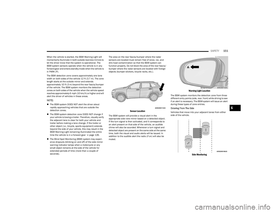
The BSM detection zone covers approximately one lane
width on both sides of the vehicle 12 ft (3.7 m). The zone
length starts at the outside mirror and extends
approximately 10 ft (3 m) beyond the rear fascia/bumper
of the vehicle. The BSM system monitors the detection
zones on both sides of the vehicle when the vehicle speed
reaches approximately 6 mph (10 km/h) or higher and will
alert the driver of vehicles in these areas.
NOTE:
The BSM system DOES NOT alert the driver about
rapidly approaching vehicles that are outside the
detection zones.
The BSM system detection zone DOES NOT change if
your vehicle is towing a trailer. Therefore, visually verify
the adjacent lane is clear for both your vehicle and
trailer before making a lane change. If the trailer or
other object (i.e., bicycle, sports equipment) extends
beyond the side of your vehicle, this may result in the
BSM Warning Light remaining illuminated the entire
time the vehicle is in a forward gear
Úpage 126.
The Blind Spot Monitoring (BSM) system may experi -
ence dropouts (blinking on and off) of the side mirror
warning indicator lamps when a motorcycle or any
small object remains at the side of the vehicle for
extended periods of time (more than a couple of
seconds). The area on the rear fascia/bumper where the radar
sensors are located must remain free of snow, ice, and
dirt/road contamination so that the BSM system can
function properly. Do not block the area of the rear fascia/
bumper where the radar sensors are located with foreign
objects (bumper stickers, bicycle racks, etc.).
Sensor Location
The BSM system will provide a visual alert in the
appropriate side view mirror based on a detected object.
If the turn signal is then activated, and it corresponds to
an alert present on that side of the vehicle, an audible
chime will also be sounded. Whenever a turn signal and
detected object are present on the same side at the same
time, both the visual and audio alerts will be issued. In
addition to the audible alert the radio (if on) will also be
muted.
Warning Light Location
The BSM system monitors the detection zone from three
different entry points (side, rear, front) while driving to see
if an alert is necessary. The BSM system will issue an alert
during these types of zone entries.
Entering From The Side
Vehicles that move into your adjacent lanes from either
side of the vehicle.
Side Monitoring
6
23_KL_OM_EN_USC_t.book Page 151
Page 155 of 276
SAFETY153
Rear Cross Path (RCP)
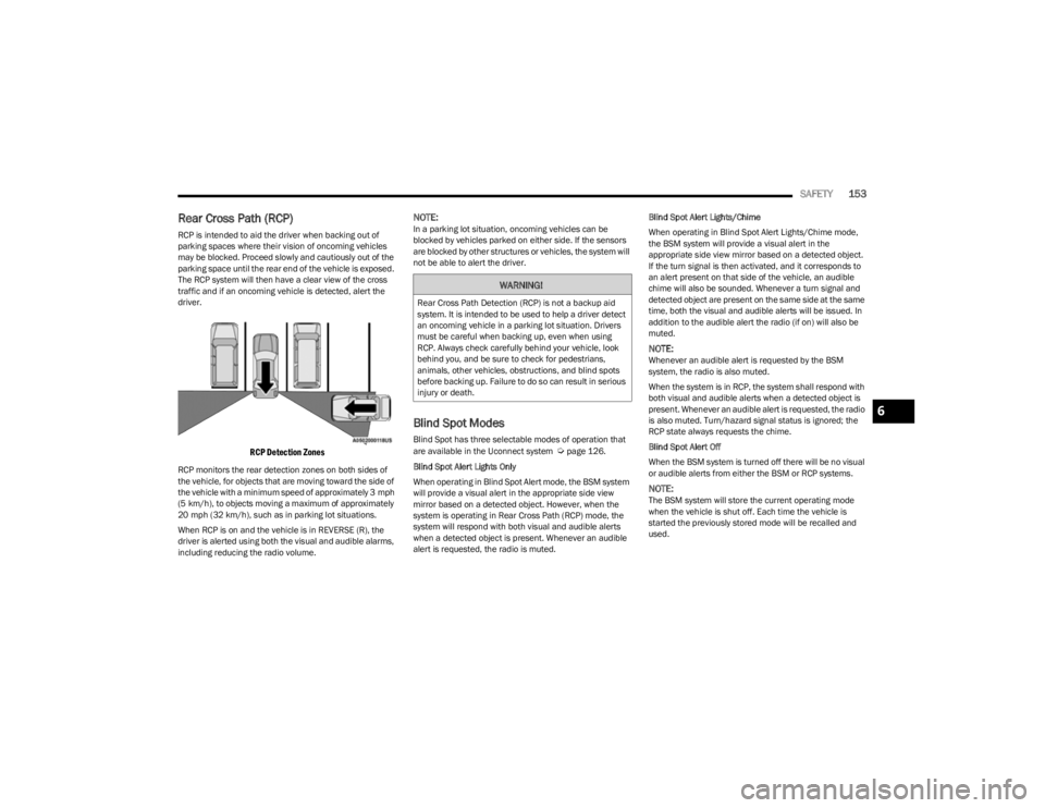
RCP is intended to aid the driver when backing out of
parking spaces where their vision of oncoming vehicles
may be blocked. Proceed slowly and cautiously out of the
parking space until the rear end of the vehicle is exposed.
The RCP system will then have a clear view of the cross
traffic and if an oncoming vehicle is detected, alert the
driver.
RCP Detection Zones
RCP monitors the rear detection zones on both sides of
the vehicle, for objects that are moving toward the side of
the vehicle with a minimum speed of approximately 3 mph
(5 km/h), to objects moving a maximum of approximately
20 mph (32 km/h), such as in parking lot situations.
When RCP is on and the vehicle is in REVERSE (R), the
driver is alerted using both the visual and audible alarms,
including reducing the radio volume.
NOTE:In a parking lot situation, oncoming vehicles can be
blocked by vehicles parked on either side. If the sensors
are blocked by other structures or vehicles, the system will
not be able to alert the driver.
Blind Spot Modes
Blind Spot has three selectable modes of operation that
are available in the Uconnect system Úpage 126.
Blind Spot Alert Lights Only
When operating in Blind Spot Alert mode, the BSM system
will provide a visual alert in the appropriate side view
mirror based on a detected object. However, when the
system is operating in Rear Cross Path (RCP) mode, the
system will respond with both visual and audible alerts
when a detected object is present. Whenever an audible
alert is requested, the radio is muted. Blind Spot Alert Lights/Chime
When operating in Blind Spot Alert Lights/Chime mode,
the BSM system will provide a visual alert in the
appropriate side view mirror based on a detected object.
If the turn signal is then activated, and it corresponds to
an alert present on that side of the vehicle, an audible
chime will also be sounded. Whenever a turn signal and
detected object are present on the same side at the same
time, both the visual and audible alerts will be issued. In
addition to the audible alert the radio (if on) will also be
muted.
NOTE:Whenever an audible alert is requested by the BSM
system, the radio is also muted.
When the system is in RCP, the system shall respond with
both visual and audible alerts when a detected object is
present. Whenever an audible alert is requested, the radio
is also muted. Turn/hazard signal status is ignored; the
RCP state always requests the chime.
Blind Spot Alert Off
When the BSM system is turned off there will be no visual
or audible alerts from either the BSM or RCP systems.
NOTE:The BSM system will store the current operating mode
when the vehicle is shut off. Each time the vehicle is
started the previously stored mode will be recalled and
used.
WARNING!
Rear Cross Path Detection (RCP) is not a backup aid
system. It is intended to be used to help a driver detect
an oncoming vehicle in a parking lot situation. Drivers
must be careful when backing up, even when using
RCP. Always check carefully behind your vehicle, look
behind you, and be sure to check for pedestrians,
animals, other vehicles, obstructions, and blind spots
before backing up. Failure to do so can result in serious
injury or death.
6
23_KL_OM_EN_USC_t.book Page 153
Page 162 of 276
160SAFETY
(Continued)
Initial Indication
If the driver is unbuckled when the ignition switch is first in
the START or ON/RUN position, a chime will signal for a
few seconds. If the driver or outboard front seat passenger
(if equipped with outboard front passenger seat BeltAlert)
is unbuckled when the ignition switch is first in the START
or ON/RUN position the Seat Belt Reminder Light will turn
on and remain on until both outboard front seat belts are
buckled. The outboard front passenger seat BeltAlert is
not active when an outboard front passenger seat is
unoccupied.
BeltAlert Warning Sequence
The BeltAlert warning sequence is activated when the
vehicle is moving above a specified vehicle speed range
and the driver or outboard front seat passenger is
unbuckled (if equipped with outboard front passenger
seat BeltAlert) (the outboard front passenger seat
BeltAlert is not active when the outboard front passenger
seat is unoccupied). The BeltAlert warning sequence
starts by blinking the Seat Belt Reminder Light and
sounding an intermittent chime. Once the BeltAlert
warning sequence has completed, the Seat Belt Reminder
Light will remain on until the seat belts are buckled. The
BeltAlert warning sequence may repeat based on vehicle
speed until the driver and occupied outboard front seat
passenger seat belts are buckled. The driver should
instruct all occupants to buckle their seat belts.
Change Of Status
If the driver or outboard front seat passenger (if equipped
with outboard front passenger seat BeltAlert) unbuckles
their seat belt while the vehicle is traveling, the BeltAlert
warning sequence will begin until the seat belts are
buckled again. The outboard front passenger seat BeltAlert is not active
when the outboard front passenger seat is unoccupied.
BeltAlert may be triggered when an animal or other items
are placed on the outboard front passenger seat or when
the seat is folded flat (if equipped). It is recommended that
pets be restrained in the rear seat (if equipped) in pet
harnesses or pet carriers that are secured by seat belts,
and cargo is properly stowed.
BeltAlert can be activated or deactivated by an authorized
dealer. FCA US LLC does not recommend deactivating
BeltAlert.
NOTE:If BeltAlert has been deactivated and the driver or
outboard front seat passenger (if equipped with outboard
front passenger seat BeltAlert) is unbuckled the Seat Belt
Reminder Light will turn on and remain on until the driver
and outboard front seat passenger seat belts are buckled.
Lap/Shoulder Belts
All seating positions in your vehicle are equipped with lap/
shoulder belts.
The seat belt webbing retractor will lock only during very
sudden stops or collisions. This feature allows the
shoulder part of the seat belt to move freely with you
under normal conditions. However, in a collision the seat
belt will lock and reduce your risk of striking the inside of
the vehicle or being thrown out of the vehicle.
WARNING!
Relying on the air bags alone could lead to more
severe injuries in a collision. The air bags work with
your seat belt to restrain you properly. In some colli -
sions, the air bags won’t deploy at all. Always wear
your seat belt even though you have air bags.
In a collision, you and your passengers can suffer
much greater injuries if you are not properly buckled
up. You can strike the interior of your vehicle or other
passengers, or you can be thrown out of the vehicle.
Always be sure you and others in your vehicle are
buckled up properly.
It is dangerous to ride in a cargo area, inside or
outside of a vehicle. In a collision, people riding in
these areas are more likely to be seriously injured or
killed.
Do not allow people to ride in any area of your vehicle
that is not equipped with seats and seat belts.
Be sure everyone in your vehicle is in a seat and
using a seat belt properly. Occupants, including the
driver, should always wear their seat belts whether or
not an air bag is also provided at their seating posi -
tion to minimize the risk of severe injury or death in
the event of a crash.
Wearing your seat belt incorrectly could make your
injuries in a collision much worse. You might suffer
internal injuries, or you could even slide out of the
seat belt. Follow these instructions to wear your seat
belt safely and to keep your passengers safe, too.
23_KL_OM_EN_USC_t.book Page 160
Page 164 of 276
162SAFETY
(Continued)
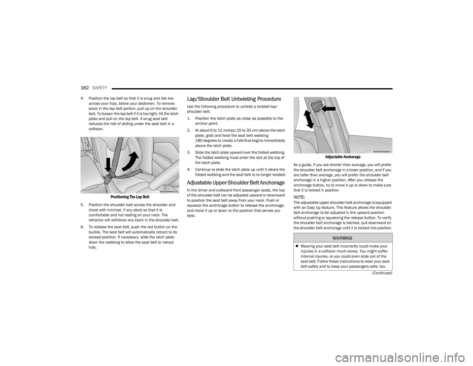
4. Position the lap belt so that it is snug and lies low
across your hips, below your abdomen. To remove
slack in the lap belt portion, pull up on the shoulder
belt. To loosen the lap belt if it is too tight, tilt the latch
plate and pull on the lap belt. A snug seat belt
reduces the risk of sliding under the seat belt in a
collision.
Positioning The Lap Belt
5. Position the shoulder belt across the shoulder and chest with minimal, if any slack so that it is
comfortable and not resting on your neck. The
retractor will withdraw any slack in the shoulder belt.
6. To release the seat belt, push the red button on the buckle. The seat belt will automatically retract to its
stowed position. If necessary, slide the latch plate
down the webbing to allow the seat belt to retract
fully.
Lap/Shoulder Belt Untwisting Procedure
Use the following procedure to untwist a twisted lap/
shoulder belt.
1. Position the latch plate as close as possible to the anchor point.
2. At about 6 to 12 inches (15 to 30 cm) above the latch plate, grab and twist the seat belt webbing
180 degrees to create a fold that begins immediately
above the latch plate.
3. Slide the latch plate upward over the folded webbing. The folded webbing must enter the slot at the top of
the latch plate.
4. Continue to slide the latch plate up until it clears the folded webbing and the seat belt is no longer twisted.
Adjustable Upper Shoulder Belt Anchorage
In the driver and outboard front passenger seats, the top
of the shoulder belt can be adjusted upward or downward
to position the seat belt away from your neck. Push or
squeeze the anchorage button to release the anchorage,
and move it up or down to the position that serves you
best.
Adjustable Anchorage
As a guide, if you are shorter than average, you will prefer
the shoulder belt anchorage in a lower position, and if you
are taller than average, you will prefer the shoulder belt
anchorage in a higher position. After you release the
anchorage button, try to move it up or down to make sure
that it is locked in position.
NOTE:The adjustable upper shoulder belt anchorage is equipped
with an Easy Up feature. This feature allows the shoulder
belt anchorage to be adjusted in the upward position
without pushing or squeezing the release button. To verify
the shoulder belt anchorage is latched, pull downward on
the shoulder belt anchorage until it is locked into position.
WARNING!
Wearing your seat belt incorrectly could make your
injuries in a collision much worse. You might suffer
internal injuries, or you could even slide out of the
seat belt. Follow these instructions to wear your seat
belt safely and to keep your passengers safe, too.
23_KL_OM_EN_USC_t.book Page 162
Page 165 of 276
SAFETY163
Second Row Center Seat Belt Operating
Instructions — Fixed Rear Seat
(If Equipped)
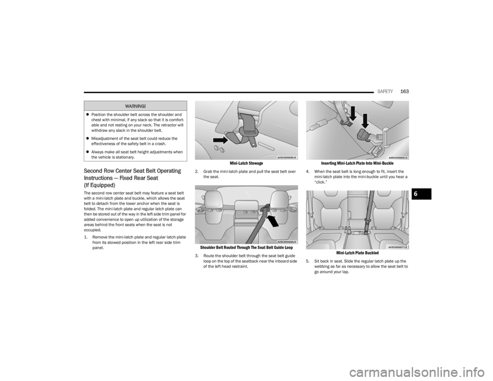
The second row center seat belt may feature a seat belt
with a mini-latch plate and buckle, which allows the seat
belt to detach from the lower anchor when the seat is
folded. The mini-latch plate and regular latch plate can
then be stored out of the way in the left side trim panel for
added convenience to open up utilization of the storage
areas behind the front seats when the seat is not
occupied.
1. Remove the mini-latch plate and regular latch plate
from its stowed position in the left rear side trim
panel.
Mini-Latch Stowage
2. Grab the mini-latch plate and pull the seat belt over the seat.
Shoulder Belt Routed Through The Seat Belt Guide Loop
3. Route the shoulder belt through the seat belt guide loop on the top of the seatback near the inboard side
of the left head restraint.
Inserting Mini-Latch Plate Into Mini-Buckle
4. When the seat belt is long enough to fit, insert the mini-latch plate into the mini-buckle until you hear a
“click.”
Mini-Latch Plate Buckled
5. Sit back in seat. Slide the regular latch plate up the webbing as far as necessary to allow the seat belt to
go around your lap.
Position the shoulder belt across the shoulder and
chest with minimal, if any slack so that it is comfort -
able and not resting on your neck. The retractor will
withdraw any slack in the shoulder belt.
Misadjustment of the seat belt could reduce the
effectiveness of the safety belt in a crash.
Always make all seat belt height adjustments when
the vehicle is stationary.
WARNING!
6
23_KL_OM_EN_USC_t.book Page 163
Page 166 of 276
164SAFETY
6. When the seat belt is long enough to fit, insert the
latch plate into the buckle until you hear a “click.”
7. Position the lap belt so that it is snug and lies low across your hips, below your abdomen. To remove
slack in the lap belt portion, pull up on the shoulder
belt. To loosen the lap belt if it is too tight, pull on the
lap belt. A snug seat belt reduces the risk of sliding
under the seat belt in a collision.
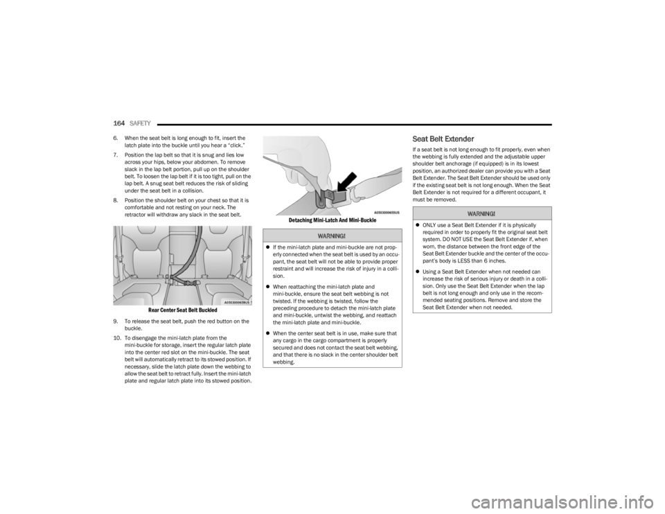
8. Position the shoulder belt on your chest so that it is comfortable and not resting on your neck. The
retractor will withdraw any slack in the seat belt.
Rear Center Seat Belt Buckled
9. To release the seat belt, push the red button on the buckle.
10. To disengage the mini-latch plate from the mini-buckle for storage, insert the regular latch plate
into the center red slot on the mini-buckle. The seat
belt will automatically retract to its stowed position. If
necessary, slide the latch plate down the webbing to
allow the seat belt to retract fully. Insert the mini-latch
plate and regular latch plate into its stowed position.
Detaching Mini-Latch And Mini-Buckle
Seat Belt Extender
If a seat belt is not long enough to fit properly, even when
the webbing is fully extended and the adjustable upper
shoulder belt anchorage (if equipped) is in its lowest
position, an authorized dealer can provide you with a Seat
Belt Extender. The Seat Belt Extender should be used only
if the existing seat belt is not long enough. When the Seat
Belt Extender is not required for a different occupant, it
must be removed.
WARNING!
If the mini-latch plate and mini-buckle are not prop -
erly connected when the seat belt is used by an occu -
pant, the seat belt will not be able to provide proper
restraint and will increase the risk of injury in a colli -
sion.
When reattaching the mini-latch plate and
mini-buckle, ensure the seat belt webbing is not
twisted. If the webbing is twisted, follow the
preceding procedure to detach the mini-latch plate
and mini-buckle, untwist the webbing, and reattach
the mini-latch plate and mini-buckle.
When the center seat belt is in use, make sure that
any cargo in the cargo compartment is properly
secured and does not contact the seat belt webbing,
and that there is no slack in the center shoulder belt
webbing.
WARNING!
ONLY use a Seat Belt Extender if it is physically
required in order to properly fit the original seat belt
system. DO NOT USE the Seat Belt Extender if, when
worn, the distance between the front edge of the
Seat Belt Extender buckle and the center of the occu -
pant’s body is LESS than 6 inches.
Using a Seat Belt Extender when not needed can
increase the risk of serious injury or death in a colli-
sion. Only use the Seat Belt Extender when the lap
belt is not long enough and only use in the recom -
mended seating positions. Remove and store the
Seat Belt Extender when not needed.
23_KL_OM_EN_USC_t.book Page 164
Page 177 of 276
SAFETY175
(Continued)
NOTE:
Air bag covers may not be obvious in the interior trim,
but they will open during air bag deployment.
After any collision, the vehicle should be taken to an
authorized dealer immediately.
Enhanced Accident Response System
In the event of an impact, if the communication network
remains intact, and the power remains intact, depending
on the nature of the event, the Occupant Restraint
Controller (ORC) will determine whether to have the
Enhanced Accident Response System perform the
following functions:
Cut off fuel to the engine (if equipped).
Cut off battery power to the electric motor (if equipped).
Flash hazard lights as long as the battery has power.
Turn on the interior lights, which remain on as long as
the battery has power or for 15 minutes from the inter -
vention of the Enhanced Accident Response System.
Unlock the power door locks. Your vehicle may also be designed to perform any of these
other functions in response to the Enhanced Accident
Response System:
Turn off the Fuel Filter Heater, Turn off the HVAC Blower
Motor, Close the HVAC Circulation Door
Cut off battery power to the:
Engine
Electric Motor (if equipped)
Electric power steering
Brake booster
Electric park brake
Automatic transmission gear selector
Horn
Front wiperNOTE:After an accident, remember to cycle the ignition to the
STOP (OFF/LOCK) position and remove the key from the
ignition switch to avoid draining the battery. Carefully
check the vehicle for fuel leaks in the engine compartment
and on the ground near the engine compartment and fuel
tank before resetting the system and starting the engine.
If there are no fuel leaks or damage to the vehicle elec -
trical devices (e.g. headlights) after an accident, reset the
system by following the procedure described below. If you
have any doubt, contact an authorized dealer.
Enhanced Accident Response System
Reset Procedure
In order to reset the Enhanced Accident Response System
functions after an event, the ignition switch must be
changed from ignition START or ON/RUN to ignition OFF.
Carefully check the vehicle for fuel leaks in the engine
compartment and on the ground near the engine
compartment and fuel tank before resetting the system
and starting the engine.
After an accident, if the vehicle will not start after
performing the reset procedure, the vehicle must be
towed to an authorized dealer to be inspected and to have
the Enhanced Accident Response System reset.
Maintaining Your Air Bag System
WARNING!
Deployed air bags and seat belt pretensioners cannot
protect you in another collision. Have the air bags, seat
belt pretensioners, and the seat belt retractor
assemblies replaced by an authorized dealer
immediately. Also, have the Occupant Restraint
Controller System serviced as well.
WARNING!
Modifications to any part of the air bag system could
cause it to fail when you need it. You could be injured
if the air bag system is not there to protect you. Do
not modify the components or wiring, including
adding any kind of badges or stickers to the steering
wheel hub trim cover or the upper passenger side of
the instrument panel. Do not modify the front
bumper, vehicle body structure, or add aftermarket
side steps or running boards.
It is dangerous to try to repair any part of the air bag
system yourself. Be sure to tell anyone who works on
your vehicle that it has an air bag system.6
23_KL_OM_EN_USC_t.book Page 175
Page 185 of 276
SAFETY183
To Install A LATCH-Compatible Child
Restraint
If the selected seating position has a Switchable
Automatic Locking Retractor (ALR) seat belt, stow the seat
belt, following the instructions below. See
Úpage 183 to
check what type of seat belt each seating position has.
1. Loosen the adjusters on the lower straps and on the tether strap of the child seat so that you can more
easily attach the hooks or connectors to the vehicle
anchorages.
2. Place the child seat between the lower anchorages for that seating position. If the second row seat can
be reclined, you may recline the seat and/or raise the
head restraint (if adjustable) to get a better fit. If the
rear seat can be moved forward and rearward in the
vehicle, you may wish to move it to its rear-most
position to make room for the child seat. You may
also move the front seat forward to allow more room
for the child seat.
3. Attach the lower hooks or connectors of the child restraint to the lower anchorages in the selected
seating position.
4. If the child restraint has a tether strap, connect it to the top tether anchorage. See
Úpage 185 for
directions to attach a tether anchor.
5. Tighten all of the straps as you push the child restraint rearward and downward into the seat.
Remove slack in the straps according to the child
restraint manufacturer’s instructions. 6. Test that the child restraint is installed tightly by
pulling back and forth on the child seat at the belt
path. It should not move more than 1 inch (25.4 mm) in any direction.
How To Stow An Unused Switchable-ALR
(ALR) Seat Belt:
When using the LATCH attaching system to install a child
restraint, stow all ALR seat belts that are not being used
by other occupants or being used to secure child
restraints. An unused belt could injure a child if they play
with it and accidentally lock the seat belt retractor. Before
installing a child restraint using the LATCH system, buckle
the seat belt behind the child restraint and out of the
child’s reach. If the buckled seat belt interferes with the
child restraint installation, instead of buckling it behind
the child restraint, route the seat belt through the child
restraint belt path and then buckle it. Do not lock the seat
belt. Remind all children in the vehicle that the seat belts
are not toys and that they should not play with them.
Installing Child Restraints Using The
Vehicle Seat Belt
Child restraint systems are designed to be secured in
vehicle seats by lap belts or the lap belt portion of a lap/
shoulder belt.
The seat belts in the passenger seating positions are
equipped with a Switchable Automatic Locking Retractor
(ALR) that is designed to keep the lap portion of the seat
belt tight around the child restraint so that it is not
necessary to use a locking clip. The ALR retractor can be
“switched” into a locked mode by pulling all of the webbing
out of the retractor and then letting the webbing retract
back into the retractor. If it is locked, the ALR will make a
clicking noise while the webbing is pulled back into the
retractor. See the “Automatic Locking Mode” description
Úpage 165 for additional information on ALR.
Please see the table and the following sections for more
information.
WARNING!
Improper installation of a child restraint to the LATCH
anchorages can lead to failure of the restraint. The
child could be badly injured or killed. Follow the child
restraint manufacturer’s directions exactly when
installing an infant or child restraint.
Child restraint anchorages are designed to withstand
only those loads imposed by correctly-fitted child
restraints. Under no circumstances are they to be
used for adult seat belts, harnesses, or for attaching
other items or equipment to the vehicle.
WARNING!
Improper installation or failure to properly secure a
child restraint can lead to failure of the restraint. The
child could be badly injured or killed.
Follow the child restraint manufacturer’s directions
exactly when installing an infant or child restraint.
6
23_KL_OM_EN_USC_t.book Page 183
Page 189 of 276
SAFETY187
(Continued)
(Continued)
SAFETY CHECKS YOU SHOULD MAKE
I
NSIDE THE VEHICLE
Seat Belts
Inspect the seat belt system periodically, checking for
cuts, frays, and loose parts. Damaged parts must be
replaced immediately. Do not disassemble or modify the
system.
If your vehicle is involved in a collision, or if you have
questions regarding seat belt or retractor conditions, take
your vehicle to an authorized FCA dealer or authorized FCA
Certified Collision Care Program facility for inspection.
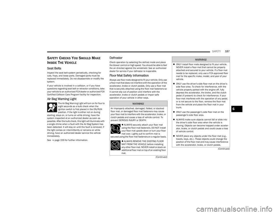
Air Bag Warning Light
The Air Bag Warning Light will turn on for four to
eight seconds as a bulb check when the
ignition switch is first placed in the ON/RUN
position. If the light is either not on during
starting, stays on, or turns on while driving, have the
system inspected at an authorized dealer as soon as
possible. After the bulb check, this light will illuminate with
a single chime when a fault with the Air Bag System has
been detected. It will stay on until the fault is removed. If
the light comes on intermittently or remains on while
driving, have an authorized dealer service the vehicle
immediately.
See
Úpage 159 for further information.
Defroster
Check operation by selecting the defrost mode and place
the blower control on high speed. You should be able to feel
the air directed against the windshield. See an authorized
dealer for service if your defroster is inoperable.
Floor Mat Safety Information
Always use floor mats designed to fit your vehicle. Only use
a floor mat that does not interfere with the operation of the
accelerator, brake or clutch pedals. Only use a floor mat
that is securely attached using the floor mat fasteners so
it cannot slip out of position and interfere with the
accelerator, brake or clutch pedals or impair safe
operation of your vehicle in other ways.
WARNING!
An improperly attached, damaged, folded, or stacked
floor mat, or damaged floor mat fasteners may cause
your floor mat to interfere with the accelerator, brake, or
clutch pedals and cause a loss of vehicle control. To
prevent SERIOUS INJURY or DEATH:
ALWAYS securely attach your floor mat
using the floor mat fasteners. DO NOT install
your floor mat upside down or turn your floor
mat over. Lightly pull to confirm mat is
secured using the floor mat fasteners on a regular basis.
ALWAYS REMOVE THE EXISTING FLOOR
MAT FROM THE VEHICLE before installing
any other floor mat. NEVER install or stack an
additional floor mat on top of an existing floor
mat.
ONLY install floor mats designed to fit your vehicle.
NEVER install a floor mat that cannot be properly
attached and secured to your vehicle. If a floor mat
needs to be replaced, only use a FCA approved floor
mat for the specific make, model, and year of your
vehicle.
ONLY use the driver’s side floor mat on the driver’s
side floor area. To check for interference, with the
vehicle properly parked with the engine off, fully
depress the accelerator, the brake, and the clutch
pedal (if present) to check for interference. If your
floor mat interferes with the operation of any pedal,
or is not secure to the floor, remove the floor mat
from the vehicle and place the floor mat in your
trunk.
ONLY use the passenger’s side floor mat on the
passenger’s side floor area.
ALWAYS make sure objects cannot fall or slide into
the driver’s side floor area when the vehicle is
moving. Objects can become trapped under acceler -
ator, brake, or clutch pedals and could cause a loss
of vehicle control.
NEVER place any objects under the floor mat (e.g.,
towels, keys, etc.). These objects could change the
position of the floor mat and may cause interference
with the accelerator, brake, or clutch pedals.
WARNING!
6
23_KL_OM_EN_USC_t.book Page 187
Page 193 of 276
IN CASE OF EMERGENCY191
The Device Screen will display the following message
“Vehicle device requires service. Please contact an
authorized dealer.”
An In-Vehicle Audio message will state “Vehicle device
requires service. Please contact an authorized dealer.”
Even if the SOS Call system is fully functional, factors
beyond FCA US LLC’s control may prevent or stop the SOS
Call system operation. These include, but are not limited
to, the following factors:
The ignition is in the OFF position
The vehicle’s electrical systems are not intact
The SOS Call system software and/or hardware are
damaged during a crash
The vehicle battery loses power or becomes discon -
nected during a vehicle crash
LTE (voice/data) 4G (data) network and/or Global Posi -
tioning Satellite signals are unavailable or obstructed
Equipment malfunction at the SOS operator facility
Operator error by the SOS operator
LTE (voice/data) 4G (data) network congestion
Weather
Buildings, structures, geographic terrain, or tunnels
NOTE:Changes or modifications not expressly approved by the
party responsible for compliance could void the user's
authority to operate the equipment.
Automatic SOS — If Equipped
Automatic SOS is a hands-free safety service that can
immediately connect you with help in the event that your
vehicle’s airbags deploy. Please refer to your provided
radio supplement for complete information.
ASSIST Call
The ASSIST Button is used to automatically connect you to
any one of the following support centers:
Roadside Assistance – If you get a flat tire, or need a
tow, just push the ASSIST button and you’ll be
connected to someone who can help. Roadside Assis -
tance will know what vehicle you’re driving and its loca -
tion. Additional fees may apply for roadside assistance.
SiriusXM Guardian™ Customer Care – In-vehicle
support for SiriusXM Guardian™.
Vehicle Customer Care – Total support for all other
vehicle issues.
Uconnect Customer Care - Total support for Radio,
Phone and NAV issues.JACKING AND TIRE CHANGING
WARNING!
Ignoring the Rearview Mirror light could mean you
will not have SOS Call services. If the Rearview Mirror
light is illuminated, have an authorized dealer
service the SOS Call system immediately.
The Occupant Restraint Control module turns on the
air bag Warning Light on the instrument panel if a
malfunction in any part of the system is detected. If
the Air Bag Warning Light is illuminated, have an
authorized dealer service the Occupant Restraint
Control system immediately.
CAUTION!
To avoid damage to the mirror during cleaning, never
spray any cleaning solution directly onto the mirror.
Apply the solution onto a clean cloth and wipe the
mirror clean.
WARNING!
Do not attempt to change a tire on the side of the
vehicle close to moving traffic. Pull far enough off the
road to avoid the danger of being hit when operating
the jack or changing the wheel.
Being under a jacked-up vehicle is dangerous. The
vehicle could slip off the jack and fall on you. You
could be crushed. Never put any part of your body
under a vehicle that is on a jack. If you need to get
under a raised vehicle, take it to a service center
where it can be raised on a lift.
Never start or run the engine while the vehicle is on
a jack.
The jack is designed to be used as a tool for changing
tires only. The jack should not be used to lift the
vehicle for service purposes. The vehicle should be
jacked on a firm level surface only. Avoid ice or slip -
pery areas.
7
23_KL_OM_EN_USC_t.book Page 191