tow JEEP CHEROKEE 2023 Owner's Manual
[x] Cancel search | Manufacturer: JEEP, Model Year: 2023, Model line: CHEROKEE, Model: JEEP CHEROKEE 2023Pages: 276, PDF Size: 12.55 MB
Page 85 of 276
STARTING AND OPERATING83
(Continued)The following indicators should be used to ensure that you
have properly engaged the transmission into the PARK
position:
When shifting into PARK, push the lock button on the
gear selector and firmly move the selector all the way
forward until it stops and is fully seated.
Look at the transmission gear position display and
verify that it indicates the PARK position.
With the brake pedal released, verify that the gear
selector will not move out of PARK.
REVERSE (R)
This range is for moving the vehicle backward. Shift into
REVERSE only after the vehicle has come to a complete
stop.
NEUTRAL (N)
Use this range when the vehicle is standing for prolonged
periods with the engine running. The engine may be
started in this range. Apply the parking brake and shift the
transmission into PARK if you must exit the vehicle.
It is dangerous to shift out of PARK or NEUTRAL if the
engine speed is higher than idle speed. If your foot is
not firmly pressing the brake pedal, the vehicle could
accelerate quickly forward or in reverse. You could
lose control of the vehicle and hit someone or some -
thing. Only shift into gear when the engine is idling
normally and your foot is firmly pressing the brake
pedal.
Unintended movement of a vehicle could injure
those in or near the vehicle. As with all vehicles, you
should never exit a vehicle while the engine is
running. Before exiting a vehicle, always come to a
complete stop, then apply the parking brake, shift
the transmission into PARK, turn the engine OFF, and
remove the key fob. When the ignition is in the OFF
(key removal) position (or, with Keyless Enter ‘n Go™,
when the ignition is in the OFF position), the trans -
mission is locked in PARK, securing the vehicle
against unwanted movement.
When leaving the vehicle, always make sure the igni -
tion is in the OFF position, remove the key fob from
the vehicle, and lock the vehicle.
Never leave children alone in a vehicle, or with
access to an unlocked vehicle. Allowing children to
be in a vehicle unattended is dangerous for a
number of reasons. A child or others could be seri -
ously or fatally injured. Children should be warned
not to touch the parking brake, brake pedal or the
transmission gear selector.
WARNING!
Do not leave the key fob in or near the vehicle (or in
a location accessible to children), and do not leave
the ignition (in a vehicle equipped with Keyless
Enter ‘n Go™) in the ACC or ON/RUN position. A child
could operate power windows, other controls, or
move the vehicle.
CAUTION!
Before moving the transmission gear selector out of
PARK, you must turn the ignition to the ON/RUN
mode, and also press the brake pedal. Otherwise,
damage to the gear selector could result.
DO NOT race the engine when shifting from PARK or
NEUTRAL into another gear range, as this can
damage the drivetrain.
WARNING!
WARNING!
Do not coast in NEUTRAL and never turn off the ignition
to coast down a hill. These are unsafe practices that
limit your response to changing traffic or road
conditions. You might lose control of the vehicle and
have a collision.
CAUTION!
Towing the vehicle, coasting, or driving for any other
reason with the transmission in NEUTRAL can cause
severe transmission damage.
If Recreational Towing see
Úpage 120.
If Towing A Disabled Vehicle see
Úpage 205.
4
23_KL_OM_EN_USC_t.book Page 83
Page 86 of 276
84STARTING AND OPERATING
DRIVE (D)
This range should be used for most city and highway
driving. It provides the smoothest upshifts and downshifts,
and the best fuel economy. The transmission
automatically upshifts through all forward gears.
When frequent transmission shifting occurs (such as
when operating the vehicle under heavy loading
conditions, in hilly terrain, traveling into strong head
winds, or while towing a heavy trailer), use the AutoStick
shift control to select a lower gear
Úpage 84. Under
these conditions, using a lower gear will improve
performance and extend transmission life by reducing
excessive shifting and heat buildup.
If the transmission temperature exceeds normal operating
limits, the transmission controller may modify the
transmission shift schedule, reduce engine torque, and/or
expand the range of torque converter clutch engagement.
This is done to prevent transmission damage due to
overheating.
If the transmission becomes extremely hot, the
Transmission Temperature Warning Light may illuminate,
and the transmission may operate differently until the
transmission cools down.
During cold temperatures, transmission operation may be
modified depending on engine and transmission
temperature as well as vehicle speed. This feature
improves warm-up time of the engine and transmission to
achieve maximum efficiency. Engagement of the torque
converter clutch, and shifts into EIGHTH or NINTH gear,
are inhibited until the transmission fluid is warm
Úpage 85. Normal operation will resume once the
transmission temperature has risen to a suitable level.
SPORT — If Equipped
This mode alters the transmission's automatic shift
schedule for sportier driving. Upshift speeds are increased
to make full use of available engine power.
SPORT mode is activated using the rotary switch on the
center console
Úpage 88.
Transmission Limp Home Mode
Transmission function is monitored electronically for
abnormal conditions. If a condition is detected that could
result in transmission damage, Transmission Limp Home
mode is activated. In this mode, the transmission may
operate only in a fixed gear, or may remain in NEUTRAL.
The Malfunction Indicator Light (MIL) may be illuminated.
Limp Home mode may allow the vehicle to be driven to an
authorized dealer for service without damaging the
transmission.
In the event of a momentary problem, the transmission
can be reset to regain all forward gears by performing the
following steps:
1. Stop the vehicle.
2. Shift the transmission into PARK.
3. Turn the ignition to the OFF position.
4. Wait approximately 10 seconds.
5. Restart the engine.
6. Shift into the desired gear range. If the problem is no longer detected, the transmission will return to
normal operation.
NOTE:Even if the transmission can be reset, we recommend that
you visit an authorized dealer at your earliest possible convenience. An authorized dealer has diagnostic
equipment to assess the condition of your transmission. If
the transmission cannot be reset, authorized dealer
service is required.
AutoStick
AutoStick is a driver interactive transmission feature
providing manual shift control, giving you more control of
the vehicle. AutoStick allows you to maximize engine
braking, eliminate undesirable upshifts and downshifts,
and improve overall vehicle performance. This feature can
also provide you with more control during passing, city
driving, cold slippery conditions, mountain driving, trailer
towing and many other situations.
Operation
When the gear selector is in the AutoStick position (beside
the DRIVE position), it can be moved forward and
rearward. This allows the driver to manually select the
transmission gear being used. Moving the gear selector
forward (-) triggers a downshift, and rearward (+) an
upshift. The current gear is displayed in the instrument
cluster.
NOTE:
In AutoStick mode, the transmission will only shift up or
down when the driver moves the gear selector rearward (+)
or forward (-), except as follows:
The transmission will automatically upshift when
necessary to prevent engine overspeed.
The transmission will automatically downshift as the
vehicle slows (to prevent engine lugging) and will
display the current gear.
23_KL_OM_EN_USC_t.book Page 84
Page 88 of 276
86STARTING AND OPERATING
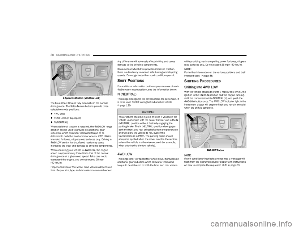
2-Speed 4x4 Switch (with Rear Lock)
The Four-Wheel Drive is fully automatic in the normal
driving mode. The Selec-Terrain buttons provide three
selectable mode positions:
4WD LOW
REAR LOCK (If Equipped)
N (NEUTRAL)
When additional traction is required, the 4WD LOW range
position can be used to provide an additional gear
reduction, which allows for increased torque to be
delivered to both the front and rear wheels. 4WD LOW is
intended for loose, slippery road surfaces only. Driving in
4WD LOW on dry, hard-surfaced roads may cause
increased tire wear and damage to driveline components.
When operating your vehicle in 4WD LOW, the engine
speed is approximately three times that of the normal
driving mode at a given road speed. Take care not to
overspeed the engine, and do not exceed 25 mph
(40 km/h).
Proper operation of four-wheel drive vehicles depends on
tires of equal size, type, and circumference on each wheel. Any difference will adversely affect shifting and cause
damage to the driveline components.
Because four-wheel drive provides improved traction,
there is a tendency to exceed safe turning and stopping
speeds. Do not go faster than road conditions permit.
SHIFT POSITIONS
For additional information on the appropriate use of each
4WD system mode position, see the information below:
N (NEUTRAL)
This range disengages the driveline from the powertrain. It
is to be used for flat towing behind another vehicle
Úpage 120.
4WD LOW
This range is for low speed four-wheel drive. It provides an
additional gear reduction which allows for increased
torque to be delivered to both the front and rear wheels
while providing maximum pulling power for loose, slippery
road surfaces only. Do not exceed 25 mph (40 km/h).
NOTE:For further information on the various positions and their
intended uses Úpage 88.
SHIFTING PROCEDURES
Shifting Into 4WD LOW
With the vehicle at speeds of 0 to 3 mph (0 to 5 km/h), the
ignition in the ON/RUN position and the engine running,
shift the transmission into NEUTRAL (N), and push the
4WD LOW button once. The 4WD LOW indicator light in the
instrument cluster will begin to flash and remain on solid
when the shift is complete.
4WD LOW Button
NOTE:
If shift conditions/interlocks are not met, a message will
flash from the instrument cluster display with instructions
on how to complete the requested shift
Úpage 63.
WARNING!
You or others could be injured or killed if you leave the
vehicle unattended with the power transfer unit in the N
(NEUTRAL) position without first fully engaging the
parking brake. The N (NEUTRAL) position disengages
both the front and rear driveshafts from the powertrain
and will allow the vehicle to roll, even if the
transmission is in PARK. The parking brake should
always be applied when the driver is not in the vehicle,
unless the vehicle is otherwise secured (for example,
when attached to the tow vehicle).
23_KL_OM_EN_USC_t.book Page 86
Page 94 of 276
92STARTING AND OPERATING
(Continued)
To Deactivate
A tap on the brake pedal, pushing the CANC button, or
normal brake pressure will deactivate the Cruise Control
system without erasing the set speed from memory.
The following conditions will also deactivate the Cruise
Control without erasing the set speed from memory:
Vehicle parking brake is applied
Stability event occurs
Gear selector is moved out of DRIVE
Engine overspeed occurs
Pushing the on/off button or placing the ignition in the OFF
position, will erase the set speed from memory.
ADAPTIVE CRUISE CONTROL (ACC)
Adaptive Cruise Control (ACC) increases the driving
convenience provided by Cruise Control while traveling on
highways and major roadways. However, it is not a safety
system and not designed to prevent collisions. The Cruise
Control function performs differently
Úpage 90.
ACC will allow you to keep Cruise Control engaged in light
to moderate traffic conditions without the constant need
to reset your Cruise Control. ACC utilizes a radar sensor
and a forward facing camera designed to detect a vehicle
directly ahead of you.
NOTE:
If the ACC sensor detects a vehicle ahead, ACC will
apply limited braking or acceleration (not to exceed the
original set speed) automatically to maintain a preset
following distance, while matching the speed of the
vehicle ahead.
Any chassis/suspension or tire size modifications to
the vehicle will affect the performance of the Adaptive
Cruise Control and Forward Collision Warning system.
Fixed Speed Cruise Control will not detect vehicles
directly ahead of you. Always be aware of the feature
selected
Úpage 262.
WARNING!
Adaptive Cruise Control (ACC) is a convenience
system. It is not a substitute for active driver involve -
ment. It is always the driver’s responsibility to be
attentive of road, traffic, and weather conditions,
vehicle speed, distance to the vehicle ahead and,
most importantly, brake operation to ensure safe
operation of the vehicle under all road conditions.
Your complete attention is always required while
driving to maintain safe control of your vehicle.
Failure to follow these warnings can result in a colli -
sion and death or serious personal injury.
The ACC system:
Does not react to pedestrians, oncoming vehi -
cles, and stationary objects (e.g., a stopped
vehicle in a traffic jam or a disabled vehicle).
Cannot take street, traffic, and weather condi -
tions into account, and may be limited upon
adverse sight distance conditions.
Does not always fully recognize complex driving
conditions, which can result in wrong or missing
distance warnings.
Will bring the vehicle to a complete stop and
hold the vehicle in the stop position for approxi -
mately three minutes when following a vehicle
ahead. If the vehicle ahead does not start
moving within three minutes, the parking brake
will be activated, and the ACC system will be
canceled.
You should switch off the ACC system:
When driving in fog, heavy rain, heavy snow,
sleet, heavy traffic, and complex driving situa-
tions (i.e., in highway construction zones).
When entering a turn lane or highway off-ramp;
when driving on roads that are winding, icy,
snow-covered, slippery, or have steep uphill or
downhill slopes.
When towing a trailer up or down steep slopes.
When circumstances do not allow safe driving at
a constant speed.
WARNING!
23_KL_OM_EN_USC_t.book Page 92
Page 100 of 276
98STARTING AND OPERATING
Precautions While Driving With ACC
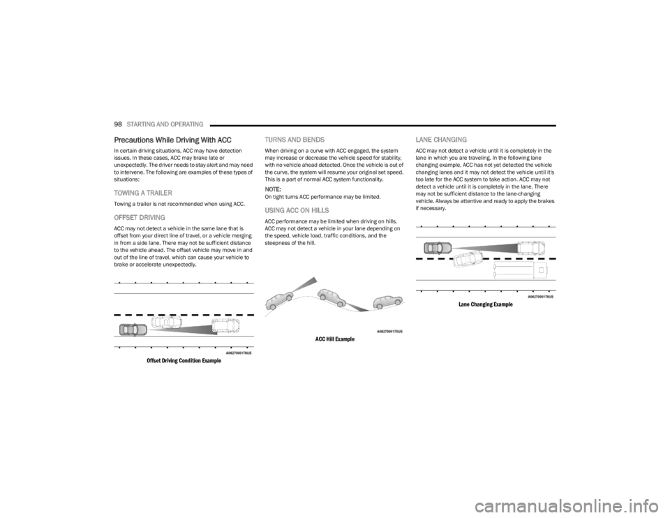
In certain driving situations, ACC may have detection
issues. In these cases, ACC may brake late or
unexpectedly. The driver needs to stay alert and may need
to intervene. The following are examples of these types of
situations:
TOWING A TRAILER
Towing a trailer is not recommended when using ACC.
OFFSET DRIVING
ACC may not detect a vehicle in the same lane that is
offset from your direct line of travel, or a vehicle merging
in from a side lane. There may not be sufficient distance
to the vehicle ahead. The offset vehicle may move in and
out of the line of travel, which can cause your vehicle to
brake or accelerate unexpectedly.
Offset Driving Condition Example
TURNS AND BENDS
When driving on a curve with ACC engaged, the system
may increase or decrease the vehicle speed for stability,
with no vehicle ahead detected. Once the vehicle is out of
the curve, the system will resume your original set speed.
This is a part of normal ACC system functionality.
NOTE:On tight turns ACC performance may be limited.
USING ACC ON HILLS
ACC performance may be limited when driving on hills.
ACC may not detect a vehicle in your lane depending on
the speed, vehicle load, traffic conditions, and the
steepness of the hill.
ACC Hill Example
LANE CHANGING
ACC may not detect a vehicle until it is completely in the
lane in which you are traveling. In the following lane
changing example, ACC has not yet detected the vehicle
changing lanes and it may not detect the vehicle until it's
too late for the ACC system to take action. ACC may not
detect a vehicle until it is completely in the lane. There
may not be sufficient distance to the lane-changing
vehicle. Always be attentive and ready to apply the brakes
if necessary.
Lane Changing Example
23_KL_OM_EN_USC_t.book Page 98
Page 101 of 276
STARTING AND OPERATING99
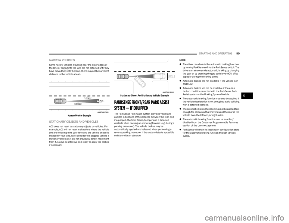
NARROW VEHICLES
Some narrow vehicles traveling near the outer edges of
the lane or edging into the lane are not detected until they
have moved fully into the lane. There may not be sufficient
distance to the vehicle ahead.
Narrow Vehicle Example
STATIONARY OBJECTS AND VEHICLES
ACC does not react to stationary objects or vehicles. For
example, ACC will not react in situations where the vehicle
you are following exits your lane and the vehicle ahead is
stopped in your lane. It will consider this stopped vehicle a
stationary object as it did not previously detect movement
from it. Always be attentive and ready to apply the brakes
if necessary.
Stationary Object And Stationary Vehicle Example
PARKSENSE FRONT/REAR PARK ASSIST
SYSTEM — IF EQUIPPED
The ParkSense Park Assist system provides visual and
audible indications of the distance between the rear, and
if equipped, the front fascia/bumper and a detected
obstacle when backing up or moving forward (e.g. during a
parking maneuver). The vehicle brakes may be
automatically applied and released when performing a
reverse parking maneuver if the system detects a possible
collision with an obstacle.
NOTE:
The driver can disable the automatic braking function
by turning ParkSense off via the ParkSense switch. The
driver can also override automatic braking by changing
the gear or by pressing the gas pedal over 90% of its
capacity during the braking event.
Automatic brakes are not available if the vehicle is in
4WD Low.
Automatic brakes will not be available if there is a
faulted condition detected with the ParkSense Park
Assist system or the Braking System Module.
The automatic braking function may only be applied if
the vehicle deceleration is not enough to avoid colliding
with a detected obstacle.
The automatic braking function may not be applied fast
enough for obstacles that move toward the rear of the
vehicle from the left and/or right sides.
The automatic braking function can be enabled/
disabled from the Customer Programmable Features
section of the Uconnect system.
ParkSense will retain its last known configuration state
for the automatic braking function through ignition
cycles.
4
23_KL_OM_EN_USC_t.book Page 99
Page 106 of 276
104STARTING AND OPERATING
(Continued)
When you turn ParkSense off, the instrument cluster
will display “PARKSENSE OFF.” Furthermore, once you
turn ParkSense off, it remains off until you turn it on
again, even if you cycle the ignition.
When you move the gear selector to the REVERSE posi -
tion and ParkSense is turned off, the instrument
cluster will display “PARKSENSE OFF” for as long as the
vehicle is in REVERSE.
ParkSense, when on, will reduce the volume of the
radio when it is sounding a tone.
Clean the ParkSense sensors regularly, taking care not
to scratch or damage them. The sensors must not be
covered with ice, snow, slush, mud, dirt or debris.
Failure to do so can result in the system not working
properly. The ParkSense system might not detect an
obstacle behind or in front of the fascia/bumper, or it
could provide a false indication that an obstacle is
behind or in front of the fascia/bumper.
Use the ParkSense switch to turn the ParkSense
system off if objects such as bicycle carriers, trailer
hitches, etc. are placed within 12 inches (30 cm) from
the rear fascia/bumper. Failure to do so can result in
the system misinterpreting a close object as a sensor
problem, causing the “PARKSENSE WIPE REAR
SENSORS” message to be displayed in the instrument
cluster. It may also result is false braking events.
ParkSense should be disabled when the liftgate is in
the open position. An opened liftgate could provide a
false indication that an obstacle is behind the vehicle.
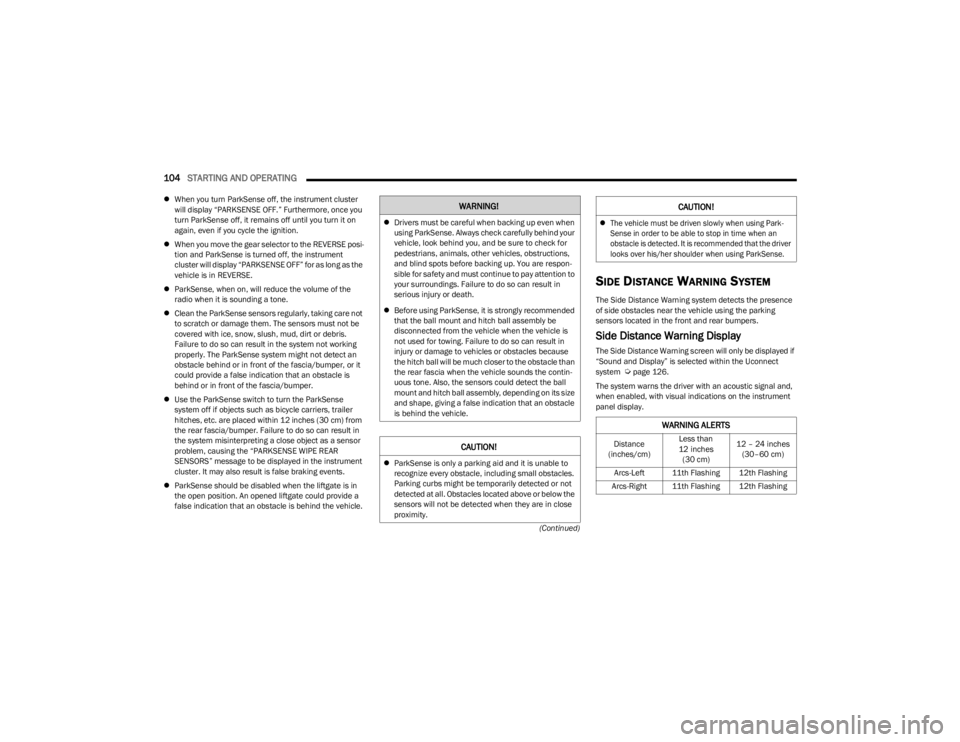
SIDE DISTANCE WARNING SYSTEM
The Side Distance Warning system detects the presence
of side obstacles near the vehicle using the parking
sensors located in the front and rear bumpers.
Side Distance Warning Display
The Side Distance Warning screen will only be displayed if
“Sound and Display” is selected within the Uconnect
system
Úpage 126.
The system warns the driver with an acoustic signal and,
when enabled, with visual indications on the instrument
panel display.
WARNING!
Drivers must be careful when backing up even when
using ParkSense. Always check carefully behind your
vehicle, look behind you, and be sure to check for
pedestrians, animals, other vehicles, obstructions,
and blind spots before backing up. You are respon -
sible for safety and must continue to pay attention to
your surroundings. Failure to do so can result in
serious injury or death.
Before using ParkSense, it is strongly recommended
that the ball mount and hitch ball assembly be
disconnected from the vehicle when the vehicle is
not used for towing. Failure to do so can result in
injury or damage to vehicles or obstacles because
the hitch ball will be much closer to the obstacle than
the rear fascia when the vehicle sounds the contin -
uous tone. Also, the sensors could detect the ball
mount and hitch ball assembly, depending on its size
and shape, giving a false indication that an obstacle
is behind the vehicle.
CAUTION!
ParkSense is only a parking aid and it is unable to
recognize every obstacle, including small obstacles.
Parking curbs might be temporarily detected or not
detected at all. Obstacles located above or below the
sensors will not be detected when they are in close
proximity.
The vehicle must be driven slowly when using Park -
Sense in order to be able to stop in time when an
obstacle is detected. It is recommended that the driver
looks over his/her shoulder when using ParkSense.
WARNING ALERTS
Distance
(inches/cm) Less than
12 inches (30 cm) 12 – 24 inches
(30–60 cm)
Arcs-Left 11th Flashing 12th Flashing
Arcs-Right 11th Flashing 12th Flashing
CAUTION!
23_KL_OM_EN_USC_t.book Page 104
Page 107 of 276
STARTING AND OPERATING105
(Continued)
NOTE:Parksense will reduce the volume of the radio if on when
the system is sounding an audible tone. An audible tone
will only sound if a collision is possible.
Activation/Deactivation
The system can operate only after driving a short distance
and if the vehicle speed is between 0 and 7 mph (0 and
11 km/h). The system can be activated/deactivated
within the Uconnect system. If the ParkSense System is
deactivated via the ParkSense switch then the Side
Distance Warning system will automatically be
deactivated.
Message on the display for Side Distance Warning
feature:
“Wipe Sensors” — This message is displayed in the case of
a failure of the Side Distance Warning system sensors.
Free the bumpers of any obstacles, ensure that the front
and rear fascia/bumper are free of snow, ice, mud, dirt
and debris to keep the ParkSense system operating
properly.
“System Not Available” — This message is displayed if the
Side Distance Warning system is not available. The failed
operation of the system might be due to the insufficient voltage from the battery or other failures on the electrical
system. Contact an authorized dealer as soon as possible
to have the electrical system checked.
ParkSense Usage Precautions
Some conditions may influence the performance of the
Side Distance Warning system:
NOTE:
Ensure that the front and rear fascia/bumper are free
of snow, ice, mud, dirt and debris to keep the Park -
Sense system operating properly.
Construction equipment, large trucks, and other vibra -
tions could affect the performance of ParkSense.
When you turn ParkSense off, the instrument cluster
display will read “PARKSENSE OFF.” Furthermore, once
you turn ParkSense off, it remains off until you turn it
on again, even if you cycle the ignition key.
ParkSense, when on, will reduce the volume of the
radio when it is sounding a tone.
Clean the ParkSense sensors regularly, taking care not
to scratch or damage them. The sensors must not be
covered with ice, snow, slush, mud, dirt or debris.
Failure to do so can result in the system not working
properly. The ParkSense system might not detect an
obstacle behind or in front of the fascia/bumper, or it
could provide a false indication that an obstacle is
behind or in front of the fascia/bumper.
The presence of a tow hook without a trailer may inter -
fere with the correct operation of the parking sensors.
Before using the ParkSense system, it is recom -
mended to remove the removable tow hook ball assembly and any attachments from the vehicle when
it is not used for towing operations.
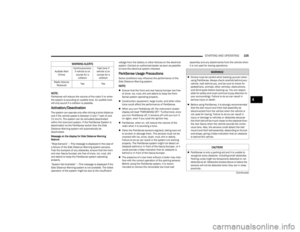
Audible Alert Chime Continuous tone
if vehicle is on course for a collision Fast tone if
vehicle is on course for a collision
Radio Volume Reduced Yes
Yes
WARNING ALERTS
WARNING!
Drivers must be careful when backing up even when
using ParkSense. Always check carefully behind your
vehicle, look behind you, and be sure to check for
pedestrians, animals, other vehicles, obstructions,
and blind spots before backing up. You are respon -
sible for safety and must continue to pay attention to
your surroundings. Failure to do so can result in
serious injury or death.
Before using ParkSense, it is strongly recommended
that the ball mount and hitch ball assembly be
disconnected from the vehicle when the vehicle is
not used for towing. Failure to do so can result in
injury or damage to vehicles or obstacles because
the hitch ball will be much closer to the obstacle than
the rear fascia when the vehicle sounds the contin -
uous tone. Also, the sensors could detect the ball
mount and hitch ball assembly, depending on its size
and shape, giving a false indication that an obstacle
is behind the vehicle.
CAUTION!
ParkSense is only a parking aid and it is unable to
recognize every obstacle, including small obstacles.
Parking curbs might be temporarily detected or not
detected at all. Obstacles located above or below the
sensors will not be detected when they are in close
proximity.
4
23_KL_OM_EN_USC_t.book Page 105
Page 116 of 276
114STARTING AND OPERATING
Payload
The payload of a vehicle is defined as the allowable load
weight a truck can carry, including the weight of the driver,
all passengers, options and cargo.
Gross Axle Weight Rating (GAWR)
The GAWR is the maximum permissible load on the front
and rear axles. The load must be distributed in the cargo
area so that the GAWR of each axle is not exceeded.
Each axle GAWR is determined by the components in the
system with the lowest load carrying capacity (axle,
springs, tires or wheels). Heavier axles, or suspension
components sometimes specified by purchasers for
increased durability, do not necessarily increase the
vehicle's GVWR.
Tire Size
The tire size on the Vehicle Certification Label represents
the actual tire size on your vehicle. Replacement tires
must be equal to the load capacity of this tire size.
Rim Size
This is the rim size that is appropriate for the tire size
listed.
Inflation Pressure
This is the cold tire inflation pressure for your vehicle for
all loading conditions up to full GAWR.
Curb Weight
The curb weight of a vehicle is defined as the total weight
of the vehicle with all fluids, including vehicle fuel, at full
capacity conditions, and with no occupants or cargo
loaded into the vehicle. The front and rear curb weight
values are determined by weighing your vehicle on a
commercial scale before any occupants or cargo are
added.
Loading
The actual total weight and the weight of the front and rear
of your vehicle at the ground can best be determined by
weighing it when it is loaded and ready for operation.
The entire vehicle should first be weighed on a commercial
scale to ensure that the GVWR has not been exceeded.
The weight on the front and rear of the vehicle should then
be determined separately to be sure that the load is
properly distributed over the front and rear axle. Weighing
the vehicle may show that the GAWR of either the front or
rear axles has been exceeded but the total load is within
the specified GVWR. If so, weight must be shifted from
front to rear or rear to front as appropriate until the
specified weight limitations are met. Store the heavier
items down low and be sure that the weight is distributed
equally. Stow all loose items securely before driving.
Improper weight distributions can have an adverse effect
on the way your vehicle steers and handles and the way
the brakes operate.TRAILER TOWING
In this section you will find safety tips and information on
limits to the type of towing you can reasonably do with your
vehicle. Before towing a trailer, carefully review this
information to tow your load as efficiently and safely as
possible.
To maintain the New Vehicle Limited Warranty coverage,
follow the requirements and recommendations in this
manual concerning vehicles used for trailer towing.
COMMON TOWING DEFINITIONS
The following trailer towing related definitions will assist
you in understanding the following information:
Gross Vehicle Weight Rating (GVWR)
The GVWR is the total allowable weight of your vehicle.
This includes driver, passengers, cargo, and tongue
weight. The total load must be limited so that you do not
exceed the GVWR
Úpage 113.
WARNING!
Do not load your vehicle any heavier than the GVWR or
the maximum front and rear GAWR. If you do, parts on
your vehicle can break, or it can change the way your
vehicle handles. This could cause you to lose control.
Overloading can shorten the life of your vehicle.
23_KL_OM_EN_USC_t.book Page 114
Page 117 of 276
STARTING AND OPERATING115
Gross Trailer Weight (GTW)
The GTW is the weight of the trailer plus the weight of all
cargo, consumables, and equipment (permanent or
temporary) loaded in or on the trailer in its “loaded and
ready for operation” condition.
The recommended way to measure GTW is to put your fully
loaded trailer on a vehicle scale. The entire weight of the
trailer must be supported by the scale.
Gross Combination Weight Rating (GCWR)
The GCWR is the total allowable weight of your vehicle and
trailer when weighed in combination.
Gross Axle Weight Rating (GAWR)
The GAWR is the maximum capacity of the front and rear
axles. Distribute the load over the front and rear axles
evenly. Make sure that you do not exceed either front or
rear GAWR. Refer to “Vehicle Loading”
Úpage 113 for
further information.
Tongue Weight (TW)
The TW is the downward force exerted on the hitch ball by
the trailer. You must consider this as part of the load on
your vehicle.
Trailer Frontal Area
The frontal area is the maximum height multiplied by the
maximum width of the front of a trailer.
Trailer Sway Control (TSC)
The TSC can be a mechanical telescoping link that can be
installed between the hitch receiver and the trailer tongue
that typically provides adjustable friction associated with
the telescoping motion to dampen any unwanted trailer
swaying motions while traveling.
The electronic TSC (if equipped) recognizes a swaying
trailer and automatically applies individual wheel brakes
and/or reduces engine power to attempt to eliminate the
trailer sway.
Weight-Carrying Hitch
A weight-carrying hitch supports the trailer tongue weight,
just as if it were luggage located at a hitch ball or some
other connecting point of the vehicle. These kinds of
hitches are commonly used to tow small and medium
sized trailers.
Weight-Distributing Hitch
A weight-distributing hitch system works by applying
leverage through spring (load) bars. They are typically
used for heavier loads to distribute trailer tongue weight to
the tow vehicle's front axle and the trailer axle(s). When
used in accordance with the manufacturer's directions, it
provides for a more level ride, offering more consistent
steering and brake control thereby enhancing towing
safety. The addition of a friction/hydraulic sway control
also dampens sway caused by traffic and crosswinds and
contributes positively to tow vehicle and trailer stability.
Trailer sway control and a weight-distributing (load
equalizing) hitch are recommended for heavier Tongue
Weights (TW) and may be required depending on vehicle
and trailer configuration/loading to comply with Gross Axle
Weight Rating (GAWR) requirements.
WARNING!
If the Gross Trailer Weight (GTW) is 3,500 lb (1,587 kg)
or more, it is mandatory to use a weight-distributing
hitch to ensure stable handling of your vehicle. If you
use a standard weight-carrying hitch, you could lose
control of your vehicle and cause a collision.
WARNING!
It is important that you do not exceed the maximum
front or rear GAWR. A dangerous driving condition can
result if either rating is exceeded. You could lose control
of the vehicle and have a collision.
WARNING!
An improperly adjusted weight-distributing hitch
system may reduce handling, stability, braking
performance, and could result in a collision.
Weight-distributing hitch systems may not be
compatible with surge brake couplers. Consult with
your hitch and trailer manufacturer or a reputable
Recreational Vehicle dealer for additional informa -
tion.
4
23_KL_OM_EN_USC_t.book Page 115