tow JEEP CHEROKEE 2023 User Guide
[x] Cancel search | Manufacturer: JEEP, Model Year: 2023, Model line: CHEROKEE, Model: JEEP CHEROKEE 2023Pages: 276, PDF Size: 12.55 MB
Page 58 of 276
56GETTING TO KNOW YOUR VEHICLE
PINCH PROTECT FEATURE
This feature will detect an obstruction in the closing of the
sunroof during the Express Close operation. If an
obstruction in the path of the sunroof is detected, the
sunroof will automatically retract. Remove the obstruction
if this occurs.
NOTE:If three consecutive sunroof close attempts result in Pinch
Protect reversals, Pinch Protect will disable and the
sunroof must be closed in Manual Mode.
VENTING SUNROOF
Push and release the Vent switch within one-half second
and the sunroof will open to the vent position. This is
called “Express Vent”, and it will occur regardless of
sunroof position. During Express Vent operation, any
movement of the switch will stop the sunroof.
IGNITION OFF OPERATION
The power sunroof switch will remain active for up to
approximately 10 minutes after the ignition switch is
placed in the OFF position. Opening either front door will
cancel this feature.
NOTE:Ignition Off timing is programmable through the Uconnect
system Úpage 126.
SUNROOF MAINTENANCE
Use only a non-abrasive cleaner and a soft cloth to clean
the glass panel. Periodically check for and clear out any
debris that may have collected in the tracks.
HOOD
OPENING THE HOOD
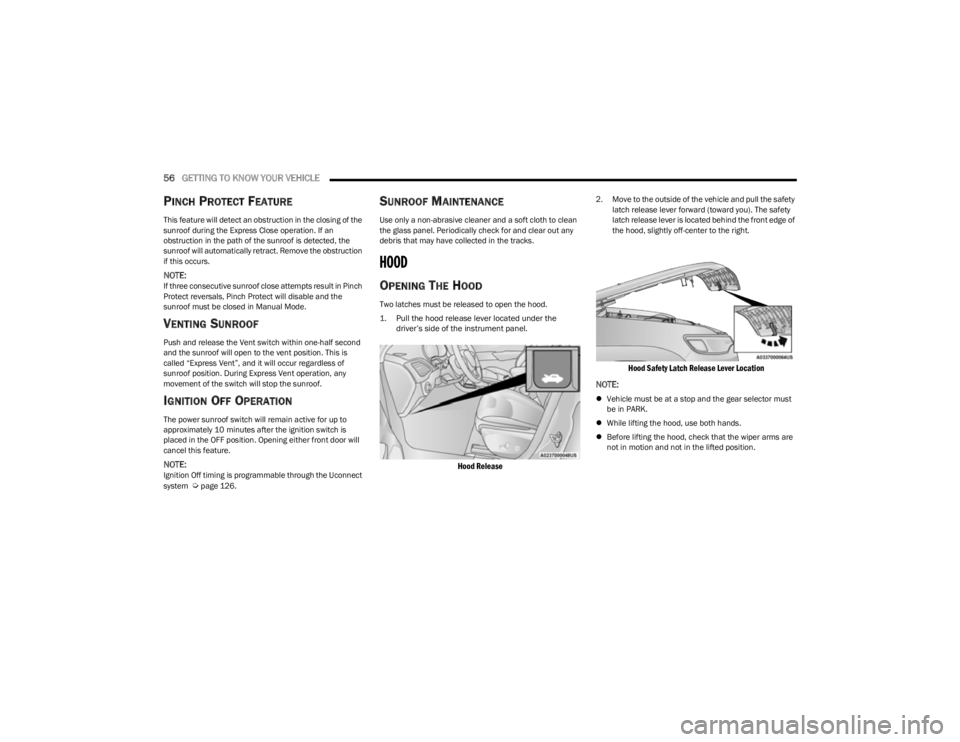
Two latches must be released to open the hood.
1. Pull the hood release lever located under the
driver’s side of the instrument panel.
Hood Release
2. Move to the outside of the vehicle and pull the safety latch release lever forward (toward you). The safety
latch release lever is located behind the front edge of
the hood, slightly off-center to the right.
Hood Safety Latch Release Lever Location
NOTE:
Vehicle must be at a stop and the gear selector must
be in PARK.
While lifting the hood, use both hands.
Before lifting the hood, check that the wiper arms are
not in motion and not in the lifted position.
23_KL_OM_EN_USC_t.book Page 56
Page 60 of 276
58GETTING TO KNOW YOUR VEHICLE
TO LOCK/CLOSE THE LIFTGATE
There are several different ways to close the liftgate:
Manually by grabbing the liftgate closing handle and
pulling in a downward motion to close the liftgate.
Release the handle when the liftgate takes over the
closing effort.
Key fob liftgate button (if equipped)
Hands-Free (if equipped)
Liftgate instrument panel button (if equipped)
Power Liftgate button on the pillar in the cargo area (if
equipped)
With a valid Passive Entry key fob within 5 ft (1.5 m) of the liftgate, pushing the Keyless Enter ‘n Go™ — Passive Entry
lock/push button located to the left of the Back Up
Camera will lock the vehicle only.
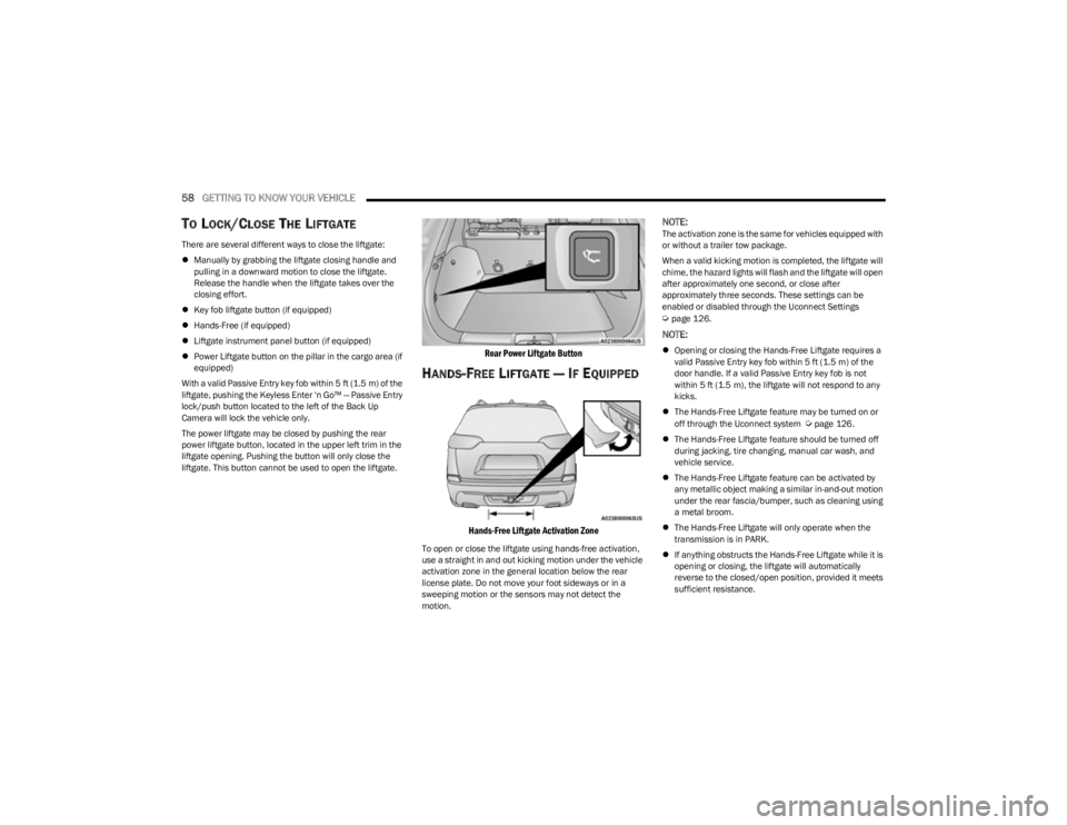
The power liftgate may be closed by pushing the rear
power liftgate button, located in the upper left trim in the
liftgate opening. Pushing the button will only close the
liftgate. This button cannot be used to open the liftgate.
Rear Power Liftgate Button
HANDS-FREE LIFTGATE — IF EQUIPPED
Hands-Free Liftgate Activation Zone
To open or close the liftgate using hands-free activation,
use a straight in and out kicking motion under the vehicle
activation zone in the general location below the rear
license plate. Do not move your foot sideways or in a
sweeping motion or the sensors may not detect the
motion.
NOTE:The activation zone is the same for vehicles equipped with
or without a trailer tow package.
When a valid kicking motion is completed, the liftgate will
chime, the hazard lights will flash and the liftgate will open
after approximately one second, or close after
approximately three seconds. These settings can be
enabled or disabled through the Uconnect Settings
Úpage 126.
NOTE:
Opening or closing the Hands-Free Liftgate requires a
valid Passive Entry key fob within 5 ft (1.5 m) of the
door handle. If a valid Passive Entry key fob is not
within 5 ft (1.5 m), the liftgate will not respond to any
kicks.
The Hands-Free Liftgate feature may be turned on or
off through the Uconnect system
Úpage 126.
The Hands-Free Liftgate feature should be turned off
during jacking, tire changing, manual car wash, and
vehicle service.
The Hands-Free Liftgate feature can be activated by
any metallic object making a similar in-and-out motion
under the rear fascia/bumper, such as cleaning using
a metal broom.
The Hands-Free Liftgate will only operate when the
transmission is in PARK.
If anything obstructs the Hands-Free Liftgate while it is
opening or closing, the liftgate will automatically
reverse to the closed/open position, provided it meets
sufficient resistance.
23_KL_OM_EN_USC_t.book Page 58
Page 69 of 276
GETTING TO KNOW YOUR INSTRUMENT PANEL67
INSTRUMENT CLUSTER DISPLAY
S
ELECTABLE ITEMS
The instrument cluster display can be used to view the
following main menu items:
NOTE:Depending on the vehicles options, feature settings may
vary Úpage 63.
BATTERY SAVER ON/BATTERY SAVER
M
ODE MESSAGE — ELECTRICAL LOAD
R
EDUCTION ACTIONS — IF EQUIPPED
This vehicle is equipped with an Intelligent Battery Sensor
(IBS) to perform additional monitoring of the electrical
system and status of the vehicle battery.
In cases when the IBS detects charging system failure, or
the vehicle battery conditions are deteriorating, electrical
load reduction actions will take place to extend the driving
time and distance of the vehicle. This is done by reducing
power to or turning off non-essential electrical loads.
Load reduction is only active when the engine is running.
It will display a message if there is a risk of battery
depletion to the point where the vehicle may stall due to
lack of electrical supply, or will not restart after the current
drive cycle. When load reduction is activated, the message “Battery
Saver On” or “Battery Saver Mode” will appear in the
instrument cluster display.
These messages indicate the vehicle battery has a low
state of charge and continues to lose electrical charge at
a rate that the charging system cannot sustain.
NOTE:
The charging system is independent from load reduc -
tion. The charging system performs a diagnostic on the
charging system continuously.
If the Battery Charge Warning Light is on it may indicate
a problem with the charging system
Úpage 69.
The electrical loads that may be switched off (if equipped),
and vehicle functions which can be effected by load
reduction:
Heated Seats / Vented Seats / Heated Wheel
Heated / Cooled Cup Holders — If Equipped
Rear Defroster And Heated Mirrors
HVAC System
150W Power Inverter System
Audio and Telematics System
Loss of the battery charge may indicate one or more of the
following conditions:
The charging system cannot deliver enough electrical
power to the vehicle system because the electrical
loads are larger than the capability of charging system.
The charging system is still functioning properly.
Turning on all possible vehicle electrical loads
(e.g. HVAC to max settings, exterior and interior
lights, overloaded power outlets +12 Volts, 150W,
USB ports) during certain driving conditions
(city driving, towing, frequent stopping).
Installing options like additional lights, upfitter elec -
trical accessories, audio systems, alarms and similar
devices.
Unusual driving cycles (short trips separated by long
parking periods).
The vehicle was parked for an extended period of time
(weeks, months).
The battery was recently replaced and was not charged
completely.
The battery was discharged by an electrical load left on
when the vehicle was parked.
The battery was used for an extended period with the
engine not running to supply radio, lights, chargers,
+12 Volts portable appliances like vacuum cleaner’s,
game consoles and similar devices.
What to do when an electrical load reduction action
message is present (“Battery Saver On” or “Battery
Saver Mode”)
During a trip:
Reduce power to unnecessary loads if possible:
Turn off redundant lights (interior or exterior).
Check what may be plugged in to power outlets
+12 Volts, 150W, USB ports.
Check HVAC settings (blower, temperature).
Check the audio settings (volume).
Speedometer Vehicle Info Stop/Start
Audio
Driver Assist Fuel Economy
Messages Screen Setup Trip
3
23_KL_OM_EN_USC_t.book Page 67
Page 71 of 276
GETTING TO KNOW YOUR INSTRUMENT PANEL69
The light will also turn on when the parking brake is
applied with the ignition switch in the ON/RUN position.
NOTE:This light only shows that the parking brake is applied. It
does not show the degree of brake application.
Battery Charge Warning Light
This warning light will illuminate when the
battery is not charging properly. If it stays on
while the engine is running, there may be a
malfunction with the charging system. Contact
an authorized dealer as soon as possible.
This indicates a possible problem with the electrical
system or a related component.
This warning light will illuminate when the battery is not
charging properly. If it stays on while the engine is running,
there may be a malfunction with the charging system.
Contact an authorized dealer as soon as possible.
Door Open Warning Light
This indicator will illuminate when a door is
ajar/open and not fully closed.
NOTE:If the vehicle is moving, there will also be a single chime.
Electric Power Steering (EPS) Fault
Warning Light
This warning light will turn on when there's a
fault with the EPS system Úpage 88.
Electronic Throttle Control (ETC) Warning
Light
This warning light will illuminate to indicate a
problem with the ETC system. If a problem is
detected while the vehicle is running, the light
will either stay on or flash depending on the
nature of the problem. Cycle the ignition when the vehicle
is safely and completely stopped and the transmission is
placed in the PARK (P) position. The light should turn off.
If the light remains on with the vehicle running, your
vehicle will usually be drivable; however, see an
authorized dealer for service as soon as possible.
NOTE:This light may turn on if the accelerator and brake pedals
are pressed at the same time.
If the light continues to flash when the vehicle is running,
immediate service is required and you may experience
reduced performance, an elevated/rough idle, or engine
stall and your vehicle may require towing. The light will
come on when the ignition is placed in the ON/RUN or
ACC/ON/RUN position and remain on briefly as a bulb
check. If the light does not come on during starting, have
the system checked by an authorized dealer.
Engine Coolant Temperature Warning
Light
This light warns of an overheated engine
condition. If the engine coolant temperature is
too high, this indicator will illuminate and a
single chime will sound.
If the light turns on while driving, safely pull over and stop
the vehicle. If the Air Conditioning (A/C) system is on, turn
it off. Also, shift the transmission into NEUTRAL and idle
the vehicle. If the temperature reading does not return to
normal, turn the engine off immediately and call for
service
Úpage 203.
Hood Open Warning Light
This warning light will illuminate when the hood
is left open and not fully closed.
NOTE:If the vehicle is moving, there will also be a single chime.
Liftgate Open Warning Light
This warning light will illuminate when the
liftgate is open.
NOTE:If the vehicle is moving, there will also be a single chime.
Oil Pressure Warning Light
This warning light will illuminate to indicate low
engine oil pressure. A chime will sound when
this light turns on and a message “Oil Pressure
Low” will display in the message screen. If the
WARNING!
Continued operation with reduced assist could pose a
safety risk to yourself and others. Service should be
obtained as soon as possible.
3
23_KL_OM_EN_USC_t.book Page 69
Page 72 of 276
70GETTING TO KNOW YOUR INSTRUMENT PANEL
light turns on while driving, pull the vehicle to the side of
the road at a safe location, stop the vehicle, shut off the
engine as soon as possible, check the oil level and correct
the oil level if it is low. Contact an authorized dealer.
Do not operate the vehicle until the cause is corrected.
This light may or may not indicate how much oil is in the
engine. If the oil level is low and corrected, the engine can
be restarted. Otherwise the vehicle should be serviced by
an authorized dealer
Úpage 208.
NOTE:The light may flash, a message in the center of the dash
may display momentarily “low oil pressure” and a chime
may occur during sharp cornering maneuvers. If this
happen it may indicate a low oil level. The oil level should
be checked and dealer service performed if this occurs.
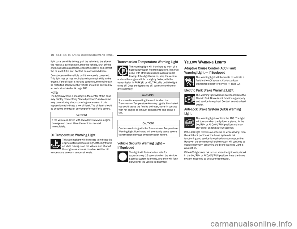
Oil Temperature Warning Light
This warning light will illuminate to indicate the
engine oil temperature is high. If the light turns
on while driving, stop the vehicle and shut off
the engine as soon as possible. Wait for oil
temperature to return to normal levels.
Transmission Temperature Warning Light
This warning light will illuminate to warn of a
high transmission fluid temperature. This may
occur with strenuous usage such as trailer
towing. If this light turns on, stop the vehicle
and run the engine at idle or slightly faster, with the
transmission in PARK (P) or NEUTRAL (N), until the light
turns off. Once the light turns off, you may continue to
drive normally.
Vehicle Security Warning Light —
If Equipped
This light will flash at a fast rate for
approximately 15 seconds when the Vehicle
Security System is arming, and then will flash
slowly until the vehicle is disarmed.
YELLOW WARNING LIGHTS
Adaptive Cruise Control (ACC) Fault
Warning Light — If Equipped
This warning light will illuminate to indicate a
fault in the ACC system. Contact a local
authorized dealer for service
Úpage 92.
Electric Park Brake Warning Light
This warning light will illuminate to indicate the
Electric Park Brake is not functioning properly
and service is required. Contact an authorized
dealer.
Anti-Lock Brake System (ABS) Warning
Light
This warning light monitors the ABS. The light
will turn on when the ignition is placed in the
ON/RUN or ACC/ON/RUN position and may
stay on for as long as four seconds.
If the ABS light remains on or turns on while driving, then
the Anti-Lock portion of the brake system is not
functioning and service is required as soon as possible.
However, the conventional brake system will continue to
operate normally, assuming the Brake Warning Light is
also not on.
If the ABS light does not turn on when the ignition is placed
in the ON/RUN or ACC/ON/RUN position, have the brake
system inspected by an authorized dealer.CAUTION!
If the vehicle is driven with low oil levels severe engine
damage can occur. Have the vehicle checked
immediately.
WARNING!
If you continue operating the vehicle when the
Transmission Temperature Warning Light is illuminated
you could cause the fluid to boil over, come in contact
with hot engine or exhaust components and cause a
fire.
CAUTION!
Continuous driving with the Transmission Temperature
Warning Light illuminated will eventually cause severe
transmission damage or transmission failure.
23_KL_OM_EN_USC_t.book Page 70
Page 73 of 276
GETTING TO KNOW YOUR INSTRUMENT PANEL71
Electronic Stability Control (ESC) Active
Warning Light — If Equipped
This warning light will indicate when the
Electronic Stability Control system is Active.
The ESC Indicator Light in the instrument
cluster will come on when the ignition is placed
in the ON/RUN or ACC/ON/RUN position, and when ESC is
activated. It should go out with the engine running. If the
ESC Indicator Light comes on continuously with the engine
running, a malfunction has been detected in the ESC
system. If this warning light remains on after several
ignition cycles, and the vehicle has been driven several
miles (kilometers) at speeds greater than 30 mph
(48 km/h), see an authorized dealer as soon as possible
to have the problem diagnosed and corrected.
The ESC OFF Indicator Light and the ESC Indicator Light
come on momentarily each time the ignition is placed
in the ON/RUN or ACC/ON/RUN position.
The ESC system will make buzzing or clicking sounds
when it is active. This is normal; the sounds will stop
when ESC becomes inactive.
This light will come on when the vehicle is in an ESC
event.
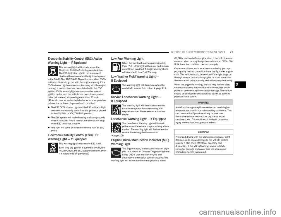
Electronic Stability Control (ESC) OFF
Warning Light — If Equipped
This warning light indicates the ESC is off.
Each time the ignition is turned to ON/RUN or
ACC/ON/RUN, the ESC system will be on, even
if it was turned off previously.
Low Fuel Warning Light
When the fuel level reaches approximately
2 gal (7.5 L) this light will turn on, and remain
on until fuel is added. A single warning chime
will sound with Low Fuel Warning.
Low Washer Fluid Warning Light —
If Equipped
This warning light will illuminate when the
windshield washer fluid is low Úpage 212.
Service LaneSense Warning Light —
If Equipped
This warning light will illuminate when the
LaneSense system is not operating and
requires service. Please see an authorized
dealer.
LaneSense Warning Light — If Equipped
The LaneSense Warning Light will be solid
yellow when the vehicle is approaching a lane
marker. The warning light will flash when the
vehicle is crossing the lane marker
Úpage 109.
Engine Check/Malfunction Indicator (MIL)
Warning Light
The Engine Check/Malfunction Indicator Light
(MIL) is a part of an Onboard Diagnostic System
called OBD II that monitors engine and
automatic transmission control systems. This
warning light will illuminate when the ignition is in the ON/RUN position before engine start. If the bulb does not
come on when turning the ignition switch from OFF to ON/
RUN, have the condition checked promptly.
Certain conditions, such as a loose or missing gas cap,
poor quality fuel, etc., may illuminate the light after engine
start. The vehicle should be serviced if the light stays on
through several typical driving styles. In most situations,
the vehicle will drive normally and will not require towing.
When the engine is running, the MIL may flash to alert
serious conditions that could lead to immediate loss of
power or severe catalytic converter damage. The vehicle
should be serviced by an authorized dealer as soon as
possible if this occurs.
WARNING!
A malfunctioning catalytic converter can reach higher
temperatures than in normal operating conditions. This
can cause a fire if you drive slowly or park over
flammable substances such as dry plants, wood,
cardboard, etc. This could result in death or serious
injury to the driver, occupants or others.
CAUTION!
Prolonged driving with the Malfunction Indicator Light
(MIL) on could cause damage to the vehicle control
system. It also could affect fuel economy and
driveability. If the MIL is flashing, severe catalytic
converter damage and power loss will soon occur.
Immediate service is required.
3
23_KL_OM_EN_USC_t.book Page 71
Page 77 of 276
GETTING TO KNOW YOUR INSTRUMENT PANEL75
(Continued)
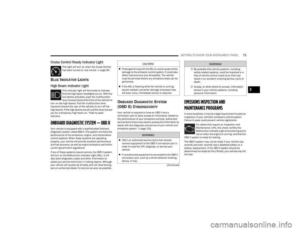
Cruise Control Ready Indicator Light
This light will turn on when the Cruise Control
has been turned on, but not set Úpage 90.
BLUE INDICATOR LIGHTS
High Beam Indicator Light
This indicator light will illuminate to indicate
that the high beam headlights are on. With the
low beams activated, push the multifunction
lever forward (toward the front of the vehicle) to
turn on the high beams. Pull the multifunction lever
rearward (toward the rear of the vehicle) to turn off the
high beams. If the high beams are off, pull the lever toward
you for a temporary high beam on, “flash to pass”
scenario.
ONBOARD DIAGNOSTIC SYSTEM — OBD II
Your vehicle is equipped with a sophisticated Onboard
Diagnostic system called OBD II. This system monitors the
performance of the emissions, engine, and transmission
control systems. When these systems are operating
properly, your vehicle will provide excellent performance
and fuel economy, as well as engine emissions well within
current government regulations.
If any of these systems require service, the OBD II system
will turn on the Malfunction Indicator Light (MIL). It will
also store diagnostic codes and other information to
assist your service technician in making repairs. Although
your vehicle will usually be drivable and not need towing,
see an authorized dealer for service as soon as possible.
ONBOARD DIAGNOSTIC SYSTEM
(OBD II) C
YBERSECURITY
Your vehicle is required to have an OBD II and a
connection port to allow access to information related to
the performance of your emissions controls. Authorized
service technicians may need to access this information to
assist with the diagnosis and service of your vehicle and
emissions system
Úpage 126.
EMISSIONS INSPECTION AND
MAINTENANCE PROGRAMS
In some localities, it may be a legal requirement to pass an
inspection of your vehicle's emissions control system.
Failure to pass could prevent vehicle registration.
For states that require an Inspection and
Maintenance (I/M), this check verifies the
Malfunction Indicator Light is functioning and is
not on when the engine is running, and that the
OBD II system is ready for testing.
The OBD ll system may not be ready if your vehicle was
recently serviced, recently had a depleted battery or a
battery replacement. If the OBD ll system should be
determined not ready for the I/M test, your vehicle may fail
the test.
CAUTION!
Prolonged driving with the MIL on could cause further
damage to the emission control system. It could also
affect fuel economy and driveability. The vehicle
must be serviced before any emissions tests can be
performed.
If the MIL is flashing while the vehicle is running,
severe catalytic converter damage and power loss
will soon occur. Immediate service is required.
WARNING!
ONLY an authorized service technician should
connect equipment to the OBD II connection port in
order to read the VIN, diagnose, or service your
vehicle.
If unauthorized equipment is connected to the OBD II
connection port, such as a driver-behavior tracking
device, it may:
Be possible that vehicle systems, including
safety related systems, could be impaired or a
loss of vehicle control could occur that may
result in an accident involving serious injury or
death.
Access, or allow others to access, information
stored in your vehicle systems, including
personal information.
WARNING!
3
23_KL_OM_EN_USC_t.book Page 75
Page 80 of 276
78STARTING AND OPERATING
(Continued)
IF ENGINE FAILS TO START
If the engine fails to start after you have followed the
“Normal Starting” procedure and the vehicle has not
experienced an Extended Park condition as previously
defined, it may be flooded. Push the accelerator pedal all
the way to the floor and hold it there while the engine is
cranking. This should clear any excess fuel in case the
engine is flooded. The starter motor will engage
automatically, run for 10 seconds, and then disengage.
Once this occurs, release the accelerator pedal and the
brake pedal, wait 10 to 15 seconds, then repeat the
“Normal Starting” procedure.AFTER STARTING
The idle speed is controlled automatically, and it will
decrease as the engine warms up.
ENGINE BREAK-IN RECOMMENDATIONS
A long break-in period is not required for the engine and
drivetrain (transmission and axle) in your vehicle.
Drive moderately during the first 300 miles (500 km).
After the initial 60 miles (100 km), speeds up to 50 or
55 mph (80 or 90 km/h) are desirable.
While cruising, brief full-throttle acceleration within the
limits of local traffic laws contributes to a good break-in.
Wide-open throttle acceleration in low gear can be
detrimental and should be avoided.
The engine oil installed in the engine at the factory is a
high-quality energy conserving type lubricant. Oil changes
should be consistent with anticipated climate conditions
under which vehicle operations will occur. For the
recommended viscosity and quality grades see
Úpage 256.
NOTE:A new engine may consume some oil during its first few
thousand miles (kilometers) of operation. This should be
considered a normal part of the break-in and not inter -
preted as a problem.
PARKING BRAKE
ELECTRIC PARK BRAKE (EPB)
Your vehicle is equipped with an EPB that offers simple
operation, and some additional features that make the
parking brake more convenient and useful.
The parking brake is primarily intended to prevent the
vehicle from rolling while parked. Before leaving the
vehicle, make sure that the parking brake is applied. Also,
be certain to leave the transmission in PARK (P).
You can engage the parking brake in two ways:
Manually, by applying the EPB switch.
Automatically, by enabling the Auto Park Brake feature
in the customer programmable features
Úpage 132.
The EPB switch is located in the center console, behind
the gear selector.
CAUTION!
To prevent damage to the starter, do not crank
continuously for more than 10 seconds at a time. Wait
10 to 15 seconds before trying again.
WARNING!
Never pour fuel or other flammable liquid into the
throttle body air inlet opening in an attempt to start
the vehicle. This could result in flash fire causing
serious personal injury.
Do not attempt to push or tow your vehicle to get it
started. Vehicles equipped with an automatic trans -
mission cannot be started this way. Unburned fuel
could enter the catalytic converter and once the
engine has started, ignite and damage the converter
and vehicle.
If the vehicle has a discharged battery, booster
cables may be used to obtain a start from a booster
battery or the battery in another vehicle. This type of
start can be dangerous if done improperly
Úpage 200.
WARNING!CAUTION!
Never use Non-Detergent Oil or Straight Mineral Oil in
the engine or damage may result.
23_KL_OM_EN_USC_t.book Page 78
Page 81 of 276
STARTING AND OPERATING79
(Continued)
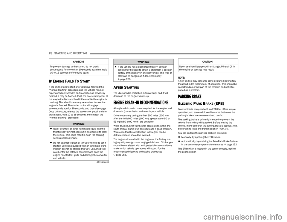
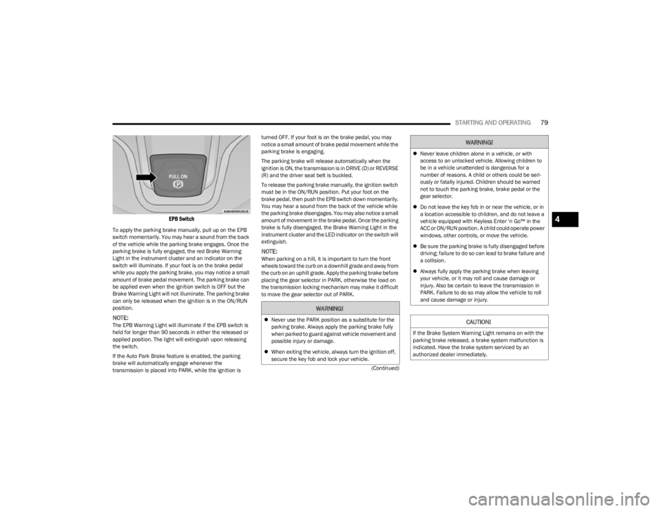
EPB Switch
To apply the parking brake manually, pull up on the EPB
switch momentarily. You may hear a sound from the back
of the vehicle while the parking brake engages. Once the
parking brake is fully engaged, the red Brake Warning
Light in the instrument cluster and an indicator on the
switch will illuminate. If your foot is on the brake pedal
while you apply the parking brake, you may notice a small
amount of brake pedal movement. The parking brake can
be applied even when the ignition switch is OFF but the
Brake Warning Light will not illuminate. The parking brake
can only be released when the ignition is in the ON/RUN
position.
NOTE:The EPB Warning Light will illuminate if the EPB switch is
held for longer than 90 seconds in either the released or
applied position. The light will extinguish upon releasing
the switch.
If the Auto Park Brake feature is enabled, the parking
brake will automatically engage whenever the
transmission is placed into PARK, while the ignition is turned OFF. If your foot is on the brake pedal, you may
notice a small amount of brake pedal movement while the
parking brake is engaging.
The parking brake will release automatically when the
ignition is ON, the transmission is in DRIVE (D) or REVERSE
(R) and the driver seat belt is buckled.
To release the parking brake manually, the ignition switch
must be in the ON/RUN position. Put your foot on the
brake pedal, then push the EPB switch down momentarily.
You may hear a sound from the back of the vehicle while
the parking brake disengages. You may also notice a small
amount of movement in the brake pedal. Once the parking
brake is fully disengaged, the Brake Warning Light in the
instrument cluster and the LED indicator on the switch will
extinguish.
NOTE:When parking on a hill, it is important to turn the front
wheels toward the curb on a downhill grade and away from
the curb on an uphill grade. Apply the parking brake before
placing the gear selector in PARK, otherwise the load on
the transmission locking mechanism may make it difficult
to move the gear selector out of PARK.
WARNING!
Never use the PARK position as a substitute for the
parking brake. Always apply the parking brake fully
when parked to guard against vehicle movement and
possible injury or damage.
When exiting the vehicle, always turn the ignition off,
secure the key fob and lock your vehicle.
Never leave children alone in a vehicle, or with
access to an unlocked vehicle. Allowing children to
be in a vehicle unattended is dangerous for a
number of reasons. A child or others could be seri -
ously or fatally injured. Children should be warned
not to touch the parking brake, brake pedal or the
gear selector.
Do not leave the key fob in or near the vehicle, or in
a location accessible to children, and do not leave a
vehicle equipped with Keyless Enter ‘n Go™ in the
ACC or ON/RUN position. A child could operate power
windows, other controls, or move the vehicle.
Be sure the parking brake is fully disengaged before
driving; failure to do so can lead to brake failure and
a collision.
Always fully apply the parking brake when leaving
your vehicle, or it may roll and cause damage or
injury. Also be certain to leave the transmission in
PARK. Failure to do so may allow the vehicle to roll
and cause damage or injury.
CAUTION!
If the Brake System Warning Light remains on with the
parking brake released, a brake system malfunction is
indicated. Have the brake system serviced by an
authorized dealer immediately.
WARNING!
4
23_KL_OM_EN_USC_t.book Page 79
Page 84 of 276
82STARTING AND OPERATING
(Continued)
NOTE:
The transmission electronics are self-calibrating; there -
fore, the first few shifts on a new vehicle may be some -
what abrupt. This is a normal condition, and precision
shifts will develop within a few hundred miles (kilome -
ters).
In the event of a mismatch between the gear selector
position and the actual transmission gear (for example,
driver selects REVERSE while driving forward), the posi -
tion indicator will blink continuously until the selector is
returned to the proper position, or the requested shift
can be completed.
The electronically controlled transmission adapts its shift
schedule based on driver inputs, along with environmental
and road conditions.
The 9-speed transmission has been developed to meet
the needs of current and future FWD/AWD vehicles.
Software and calibration is refined to optimize the
customer’s driving experience and fuel economy. By
design, some vehicle and driveline combinations utilize
NINTH gear only in very specific driving situations and
conditions.
Only shift from DRIVE to PARK or REVERSE when the
accelerator pedal is released and the vehicle is stopped.
Be sure to keep your foot on the brake pedal when shifting
between these gears.
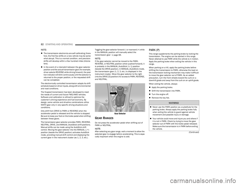
The transmission gear selector provides PARK, REVERSE,
NEUTRAL, DRIVE, and MANUAL (AutoStick) shift positions.
Manual shifts can be made using the AutoStick shift
control. Moving the gear selector into the MANUAL (-/+)
position (beside the DRIVE position) activates AutoStick
mode, providing manual shift control and displaying the
current gear in the instrument cluster (as 1, 2, 3, etc.). Toggling the gear selector forward (-) or rearward (+) while
in the MANUAL position will manually select the
transmission gear Úpage 84.
NOTE:If the gear selector cannot be moved to the PARK,
REVERSE, or NEUTRAL position (when pushed forward), it
is probably in the MANUAL (AutoStick [+/-]) position
(beside the DRIVE position). In MANUAL (AutoStick) mode,
the transmission gear (1, 2, 3, etc.) is displayed in the
instrument cluster. Move the gear selector to the right
(into the DRIVE [D] position) for access to PARK, REVERSE,
and NEUTRAL.
Gear Selector
GEAR RANGES
Do not press the accelerator pedal when shifting out of
PARK or NEUTRAL.
NOTE:After selecting any gear range, wait a moment to allow the
selected gear to engage before accelerating. This is espe
-
cially important when the engine is cold.
PARK (P)
This range supplements the parking brake by locking the
transmission. The engine can be started in this range.
Never attempt to use PARK while the vehicle is in motion.
Apply the parking brake when exiting the vehicle in this
range.
When parking on a hill, apply the parking brake before
shifting the transmission to PARK, otherwise the load on
the transmission locking mechanism may make it difficult
to move the gear selector out of PARK. As an added
precaution, turn the front wheels toward the curb on a
downhill grade and away from the curb on an uphill grade.
When exiting the vehicle, always:
Apply the parking brake.
Shift the transmission into PARK.
Turn the engine off.
Remove the key fob.
WARNING!
Never use the PARK position as a substitute for the
parking brake. Always apply the parking brake fully
when exiting the vehicle to guard against vehicle
movement and possible injury or damage.
Your vehicle could move and injure you and others if
it is not in PARK. Check by trying to move the gear
selector out of PARK with the brake pedal released.
Make sure the transmission is in PARK before exiting
the vehicle.
23_KL_OM_EN_USC_t.book Page 82