length JEEP CJ 1953 User Guide
[x] Cancel search | Manufacturer: JEEP, Model Year: 1953, Model line: CJ, Model: JEEP CJ 1953Pages: 376, PDF Size: 19.96 MB
Page 62 of 376
D
HURRICANE
F4
ENGINE d.
Remove the intake valve adjusting screw lock-
nuts from each of the rocker arm valve lash ad
justing
screws. Remove the screws from the rocker
arms.
D-76.
Inspection and
Repair
Run
a round wire brush through the bore of the
rocker
arm shaft and clean out the drilled oil holes.
Clean
out the oil
holes
in the rocker arm shaft
brackets,
and the oil
holes
and
grooves
in the bores
of the rocker arm.
Inspect
the diameter of the shaft at the rocker arm
bearing
areas. Replace the shaft if there are scores
or
abrasion marks along the length of the shaft.
Check
the shaft for alignment by rolling it across
a
smooth level surface. If the shaft
will
not
roll
freely, or if it rolls with a bumping motion, the
shaft is out of alignment and must be replaced.
Inspect
the threads of the adjusting screw
hole
in
the rocker arms and if necessary clean with a
proper
size tap. Replace the adjusting screw lock-
nut or the adjusting screw if either part is damaged
or
deformed.
Inspect
the threads in the tapped
hole
in the top
of the rocker arm shaft brackets and if necessary
clean
with a proper size tap. Replace the bracket
if
either side is worn or scored.
D-77.
Reassembly
a.
Install
two rocker arm shaft plugs, one in each
end of the shaft. Slide two
rocker
arm
shaft brackets
onto
the center of the shaft. Align the tapped
holes
in
the brackets with the drilled
holes
in the top of
the shaft and install the rocker arm shaft lock
screws,
making sure the points of the screws enter
the drilled
holes
in the shaft.
b.
Screw the intake valve adjusting screws into
the rocker arms and install the locknuts.
c.
The rocker arms are paired; that is, two of the
arms
are angled to the right and two are angled to
the left. One of each type is used on each end of
the rocker arm shaft. Slide a rocker arm with the
adjusting
screw end of the rocker arm angling
away
from the bracket
onto
the shaft so that the
adjusting
screw is on the same side of the shaft
as the mounting
hole
in the bracket.
d.
Temporarily
secure the end bracket in place by
installing
a rocker arm cover stud in the tapped
opening in the top of the support.
e. Assemble the parts on the
opposite
end of the
rocker
arm shaft repeating
steps
c and d above.
D-78. ENGINE REASSEMBLY
The
engine
reassembly procedure in the following
paragraphs
is given in the sequence to be followed
when the
engine
is being completely overhauled.
Individual
inspection,
repair,
and fitting operations
previously covered in detail are made throughout
the reassembly procedure. The reassembly pro
cedure
does
not cover accessories. If a new cylinder
block
fitted with pistons is used, many of the
operations
will
not be required.
Mount
the cylinder block in an
engine
repair stand.
If
an
engine
stand is not available, perform the fol
lowing reassembly operation in a manner designed to protect personnel against an accident and the
engine
and its parts against damage.
Note:
During
engine
reassembly, use Perfect Seal
Aerosol
Spray
Sealer
Part
No.
994757
on all
engine
gaskets to ensure against vacuum, oil, gasoline and
water
leaks. Apply to head gaskets, valve covers,
water
pumps, oil pan gaskets, radiator and heater
hose
connections, felt gaskets, gasoline and oil line
connections, stud bolts,
spark
plug threads, and
grease retainer washers. Refer to manufacturer's in
structions on container for proper application pro
cedure.
D-79.
Install
Oil
Gallery
Plug
Coat
plug threads with a suitable sealing compound
and
install the plugs in the front and
rear
ends of
the oil gallery in the cylinder block and the
rear
end of the cylinder head. Torque the plugs 20 to 25 lb-ft. [2,8 a 3,4 kg-m.].
There
is also a pipe plug
(}/g,f
[3,2 mm.] slotted, headless) in the opening in the main oil gallery inside the cylinder block at No. 2 cylinder and another pipe plug
(}/g
"
square-head) in the opening
in
the oil passage directly below the oil pump intake
passage. If
these
two pipe plugs were removed,
make
certain they are reinstalled in the locations
described above or the counterweight of the
crankshaft
might strike the projecting head of the
square-head
plug.
D-80.
Install
Tappets
Turn
the block upside down. Beginning at the
rear
end of the cylinder block, install the intake
and
exhaust valve tappets in the tappet bores in the cylinder block in the following order: one
exhaust, two intake, two exhaust, two intake, and
finally
one exhaust valve tappet.
Check
the tappet to bore fit of each tappet as it
is installed in the block. If the stem-to-block
clearance
tolerance of .0005" to .002" [0,0127 a
0,051 mm.] is
exceeded
install a new tappet fitting
within
this tolerance or ream the bore to accomo date the next oversize tappet which is available
in
.004" oversize.
D-81.
Install
Camshaft and
Thrust
Plate
Lubricate
all camshaft bearings and cam surfaces generously with clean, light
engine
oil.
Carefully,
so not to damage or score the camshaft front bear
ing,
install the camshaft, locating it properly in the bearings. Do not allow the
rear
end of the camshaft to strike sharply against the expansion plug
installed
in the
rear
end of the bore.
Install
the camshaft thrust plate. Slide the thrust
plate spacer
onto
the end of the camshaft with the
beveled inner
edge
of the spacer facing the cam
shaft. If the same camshaft is being reinstalled,
install
any shims previously removed. These shims
are
placed
between
the camshaft shoulder and the
spacer.
Torque the thrust plate attaching
bolts
20
to 26 lb-ft. [2,8 a 3,6 kg-m.].
End
play of the camshaft is determined by running
clearance
between
the
rear
face of the camshaft
gear and the thrust plate. The standard clearance 62
Page 64 of 376
D
HURRICANE
F4
ENGINE
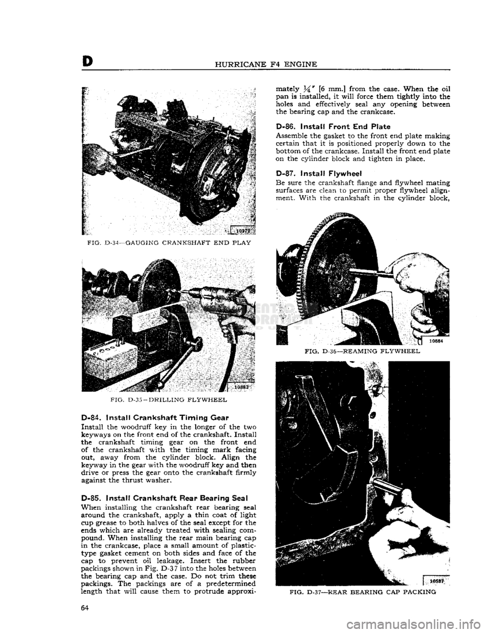
FIG.
D-34—GAUGING
CRANKSHAFT
END
PLAY
FIG.
D-35
—
DRILLING FLYWHEEL
D-84.
Install
Crankshaft Timing
Gear
Install
the woodruff key in the longer of the two keyways on the front end of the crankshaft.
Install
the crankshaft timing gear on the front end of the crankshaft with the timing
mark
facing out, away from the cylinder block. Align the
keyway in the gear with the woodruff key and then
drive
or press the gear
onto
the crankshaft firmly against the thrust washer.
D-85.
Install
Crankshaft
Rear
Bearing Seal
When
installing the crankshaft
rear
bearing seal
around
the crankshaft, apply a thin coat of light cup grease to both halves of the seal except for the
ends which are already treated with sealing com pound. When installing the
rear
main bearing cap
in
the crankcase, place a small amount of plastic- type gasket cement on both sides and face of the
cap to prevent oil leakage. Insert the rubber
packings shown in
Fig. D-3
7
into the
holes
between
the bearing cap and the case. Do not trim
these
packings. The packings are of a predetermined
length that
will
cause them to protrude approxi mately 34* [6 mm.] from the case. When the oil
pan
is installed, it
will
force them tightly into the
holes
and effectively seal any opening
between
the bearing cap and the crankcase.
D-86.
Install
Front
End Plate
Assemble the gasket to the front end plate making
certain
that it is positioned properly down to the
bottom
of the crankcase.
Install
the front end plate
on the cylinder block and tighten in place.
D-87.
Install
Flywheel
Be
sure the crankshaft flange and flywheel mating
surfaces are clean to permit proper flywheel align ment. With the crankshaft in the cylinder block,
FIG.
D-36—
REAMING FLYWHEEL
FIG.
D-37—REAR
BEARING
CAP
PACKING
64
Page 71 of 376
'Jeep*
UNIVERSAL
SERIES
SERVICE
MANUAL
D D-l 13. HURRICANE
F4
ENGINE SPECIFICATIONS
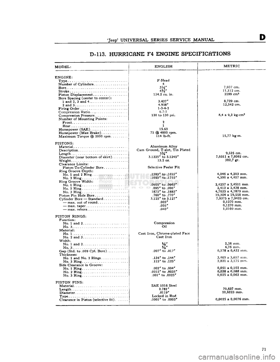
MODEL:
ENGLISH
ENGINE:
Type
Number of Cylinders
Bore
Stroke
Piston Displacement...........
Bore
Spacing (center to center): 1 and 2, 3 and 4
2 and 3
Firing
Order Compression Ratio Compression Pressure... .
Number of Mounting Points:
Front
Rear
Horsepower (SAE)
Horsepower (Max Brake) Maximum Torque @
2000
rpm.
PISTONS:
Material
Description
Length
,.
Diameter (near
bottom
of
skirt).
Weight.
Clearance
Limits:
Piston-To-Cylindcr
Bore
Ring
Groove Depth:
No. 1 and 2 Ring No. 3 Ring
Ring
Groove Width:
No. 1 Ring No. 2 Ring
No. 3 Ring
Piston Pin Hole Bore
Cylinder
Bore — Standard.....
—
max. out of round
F-Head
4
W
134.2 cu. in.
3.437"
4.938"
1-3-4-2
6.7:1
120 to 130 psi.
2
1
15.63
@
4000
rpm. 114 lb-ft. 75
-
max. taper..
-
max. rebore.
PISTON RINGS:
Function:
No. 1 and 2 No. 3. .
Material:
No. 1. .
No. 2 and 3
Width;
No. 1 and 2
No. 3. . . .
Gap
(Std. to .009 Cyl. Bore).
Thickness:
No. 1 and No. 2 Rings....
No. 3 Ring
Side Clearance in Groove:
No. 1 Ring No. 2 Ring
No. 3 Ring
PISTON
PINS:
Material
Length
Diameter
Type
Clearance
in Piston
(selective
fit).
Aluminum
Alloy
Gam
Ground, T-slot, Tin Plated
3.1225*
to
3.1245*
13.5 oz.
Selective Feeler Fit
.1593" to .1655"
.1693" to .1755"
.0955" to .0965" .095" to .096"
1875" to .1885" .760" to .770"
3.125"
to
3.127"
.005" .005" .040"
Compression
Oil
Cast
Iron,
Chrome-plated Face
Cast
Iron
.007" to .017"
.134" to .144" .115" to .125"
.002" to .004"
.0015" to .0035" .001" to .0025"
SAE
1016 Steel
2.781"
.8119"
Locked
in Rod
.0001"
to .0003"
METRIC
7,937
cm.
11,112
cm. 2199 cm*
8,729
cm.
12,542
cm.
8,4 a 9,2 kg-cm2
15,77 kg-m.
9,525
cm.
7,9311
a
7,9362
cm.
382,7
gr.
4,046
a
4,203
mm.
4,300
a
4,457
mm.
2,4257
a
2,4511
mm. 2,413 a
2,438
mm.
4,7625
a
4,7879
mm.
19,304
a
19,558
mm.
7,9375
a
7,9425
cm.
0,1270
mm.
0,1270
mm.
1,0160
mm.
2,38 mm.
4,76 mm.
0,178 a
0,432
mm.
3,403
a
3,657
mm. 2,821 a 3,175 mm.
0,051 a 0,102 mm.
0,038
a
0,088
mm.
0,025
a
0,063
mm.
70,637
mm.
20,6223
mm.
0,0025
a
0,0076
mm. 71
Page 72 of 376
D
HURRICANE
F4
ENGINE
D-l
13
HURRICHNE
F4
ENGINE
SPECIFICATIONS
(Continued)
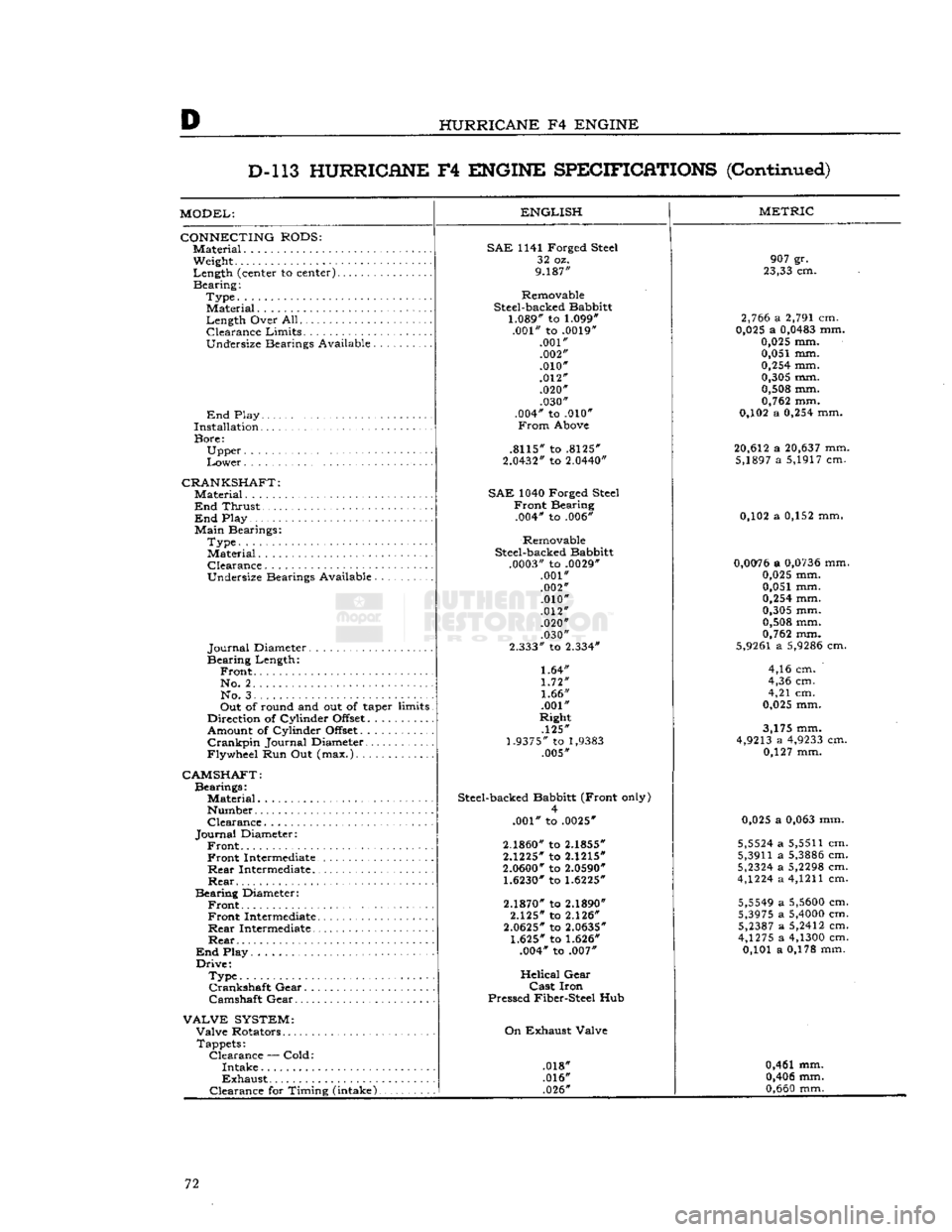
MODEL:
CONNECTING
RODS:
Material.
Weight
Length
(center to
center)......
Bearing:
Type.
Material
Length
Over
All
Clearance
Limits.
..........
Undersize
Bearings
Available
End
Play
Installation
Bore:
Upper
Lower
CRANKSHAFT:
Material....................
End
Thrust
End
Play
Main
Bearings:
Type.
Material
Clearance
Undersize
Bearings
Available
Journal
Diameter
Bearing
Length:
Front.
No.
2. . .
No.
3
Out
of
round
and out of taper
limits
Direction
of
Cylinder
Offset..........
Amount
of
Cylinder
Offset
Crankpin
Journal
Diameter
Flywheel
Run Out
(max.)
ENGLISH
CAMSHAFT:
Bearings:
Material..........
Number
Clearance.
Journal
Diameter:
Front Front
Intermediate.
Rear
Intermediate..
Rear
Bearing
Diameter:
Front Front
Intermediate.
Rear
Intermediate..
Rear
End
Play
Drive:
Type.............
Crankshaft
Gear.
. .
Camshaft
Gear
VALVE
SYSTEM:
Valve
Rotators
Tappets:
Clearance
—
Cold:
Intake
Exhaust
Clearance
for
Timing
(intake).
SAE
1141
Forged
Steel
32 oz.
9.187"
Removable
Steel-backed
Babbitt
1.089" to 1.099"
.001"
to .0019"
.001" .002"
.010"
.012" .020" .030"
.004"
to .010"
From
Above
.8115"
to .8125"
2.0432"
to 2.0440"
SAE
1040
Forged
Steel
Front
Bearing
.004*
to .006*
Removable
Steel-backed
Babbitt
.0003"
to .0029*
.001"
.002" .010"
.012" .020"
.030"
2.333"
to 2.334"
1.64"
1.72"
1.66"
.001"
Right
.125"
1.9375" to
1,9383
.005"
Steel-backed
Babbitt
(Front
only) 4
.001"
to .0025"
2.1860" to 2.1855"
2.1225"
to 2.1215"
2.0600" to 2.0590" 1.6230" to 1.6225"
2.1870" to 2.1890"
2.125"
to 2.126"
2.0625"
to 2.0635"
1.625" to 1.626"
.004*
to .007"
Helical
Gear
Cast
Iron
Pressed
Fiber-Steel
Hub
On
Exhaust
Valve
.018*
.016* .026"
METRIC
907
gr.
23,33 cm.
2,766 a 2,791 cm.
0,025 a 0,0483 mm.
0,025 mm. 0,051 mm.
0,254
mm.
0,305 mm. 0,508 mm.
0,762 mm.
0,102 a
0,254
mm.
20,612 a 20,637 mm. 5,1897 a 5,1917 cm.
0,102 a 0,152 mm,
0,0076 a 0,0736 mm. 0,025 mm.
0,051 mm.
0,254
mm.
0,305 mm.
0,508 mm.
0,762 mm.
5,9261
a 5,9286 cm.
4,16 cm.
4,36 cm.
4,21 cm.
0,025 mm.
3,175 mm.
4,9213 a 4,9233 cm. 0,127 mm.
0,025 a
0,063
mm.
5,5524 a
5,5511
cm.
5,3911
a 5,3886 cm.
5,2324 a 5,2298 cm.
4,1224 a
4,1211
cm.
5,5549 a 5,5600 cm.
5,3975 a 5,4000 cm. 5,2387 a 5,2412 cm.
4,1275 a 4,1300 cm. 0,101 a 0,178 mm.
0,461 mm. 0,406 mm.
0,660
mm. 72
Page 73 of 376
'Jeep'
UNIVERSAL SERIES SERVICE
MANUAL
D
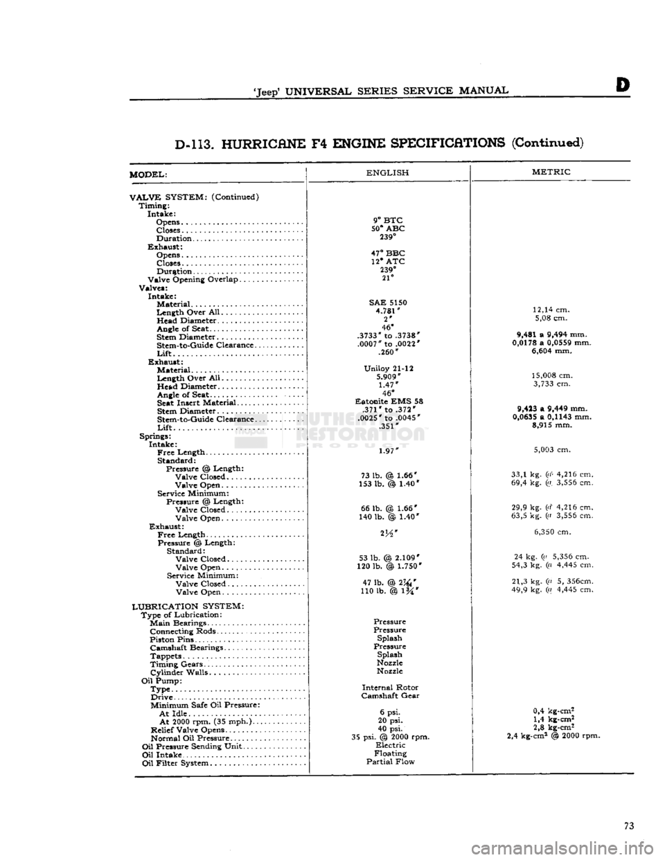
D-l 13. HURRICANE
F4
ENGINE SPECIFICATIONS
(Continued)
MODEL:
VALVE
SYSTEM:
(Continued) Timing: Intake:
Opens Closes
Duration
Exhaust: Opens
Closes Duration
Valve Opening Overlap
Valves: Intake: Material
Length Over All. Head Diameter.
.........
Angle
of Seat.
Stem
Diameter
Stem-to-Guide
Clearance..
Lift
Exhaust: Material
Length Over All Head Diameter
Angle
of
Seat Seat
Insert Material
Stem
Diameter
Stem-to-Guide
Clearance..
Lift
Springs: Intake:
Free
Length Standard: Pressure % Length: Valve Closed........
Valve Open
Service Minimum: Pressure @ Length: Valve Closed Valve Open
Exhaust:
Free
Length Pressure @ Length: Standard: Valve Closed
Valve Open
Service Minimum: Valve Closed. Valve Open
LUBRICATION SYSTEM:
Type of Lubrication:
Main
Bearings Connecting Rods
Piston Pins Camshaft Bearings
Tappets
Timing Gears.'.
Cylinder
Walls
Oil
Pump: Type Drive
Minimum
Safe
Oil Pressure:
At
Idle
At
2000
rpm. (35 mph.)..
Relief Valve Opens Normal Oil Pressure
Oil
Pressure
Sending
Unit
Oil
Intake
Oil
Filter
System
ENGLISH
9°
BTC
50°
ABC
239°
47°
BBC 12* ATC
239°
21°
SAE
5150
4.781"
2*
46°
.3733"
to
.3738"
.0007"
to
.0022'
.260"
Uniloy 21-12
5.909"
1.47"
46°
Eatonite EMS 58 .371" to .372"
.0025"
to
.0045'
.351"
1.97"
73 lb. @ 1.66"
153 lb. @ 1.40* 66 lb.
140 lb. 1.66*
)
1.40" 53 lb. (
120 lb.
2.109"
\
1.750*
47 lb. @2W
110 lb. @ l%*
Pressure
Pressure Splash
Pressure
Splash
Nozzle
Nozzle
Internal
Rotor
Camshaft
Gear
6 psi.
20 psi.
40 psi.
35 psi. @
2000
rpm.
Electric
Floating
Partial
Flow
METRIC
12,14 cm. 5,08 cm.
9,481 a
9,494
mm.
0,0178
a
0,0559
mm.
6,604
mm.
15,008
cm.
3,733
cm.
9,423
a
9,449
mm.
0,0635
a
0,1143
mm. 8,915 mm.
5,003
cm.
33,1 kg.
(i(<
4,216 cm.
69,4 kg. (a.
3,556
cm.
29,9 kg. (d 4,216 cm.
63,5 kg. ((i
3,556
cm.
6,350
cm.
24 kg. (a
5,356
cm.
54,3 kg. (a
4,445
cm.
21,3 kg. (n 5,
356cm.
49,9 kg. («
4,445
cm.
0,4 kg-cm2 1,4 kg-cm2
2,8 kg-cm2
2,4 kg-cm2 @
2000
rpm. 73
Page 85 of 376
'Jeep*
UNIVERSAL
SERIES SERVICE
MANUAL
Dl
12713
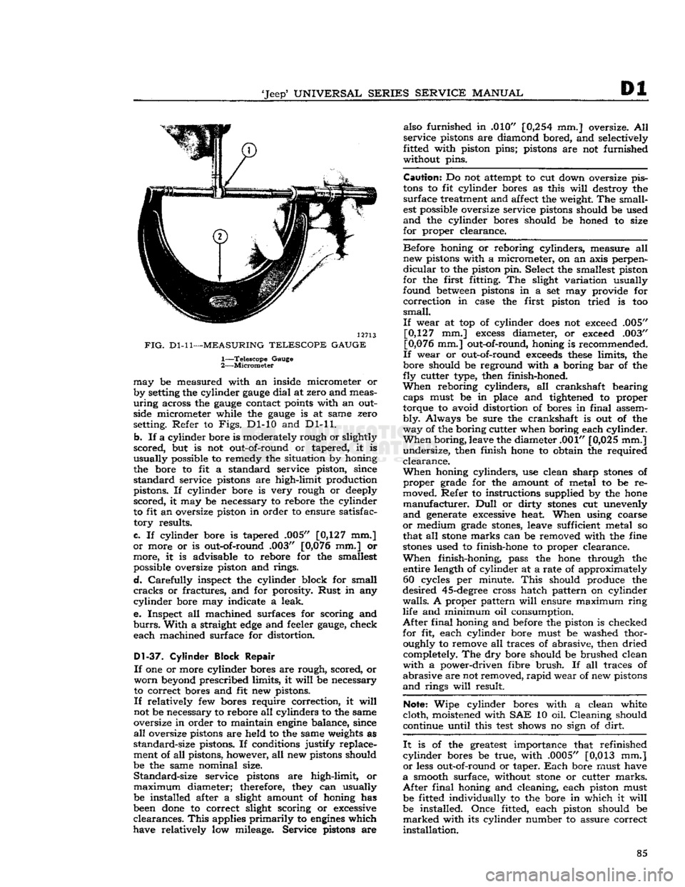
FIG.
Dl-11—MEASURING
TELESCOPE GAUGE
1—
Telescope
Gauge
2—
Micrometer
may
be measured with an inside micrometer or
by setting the cylinder
gauge
dial
at zero and meas
uring
across the
gauge
contact points with an outside micrometer while the
gauge
is at same zero
setting. Refer to
Figs.
Dl-10 and Dl-11.
b.
If a cylinder bore is moderately rough or slightly
scored,
but is not out-of-round or tapered, it is
usually
possible to remedy the situation by honing
the bore to fit a standard service piston, since
standard
service pistons are high-limit production
pistons. If cylinder bore is very rough or deeply
scored,
it may be necessary to rebore the cylinder
to fit an oversize piston in order to ensure satisfac
tory
results.
c.
If cylinder bore is tapered .005" [0,127 mm.]
or
more or is out-of-round .003" [0,076 mm.] or
more,
it is advisable to rebore for the smallest possible oversize piston and rings.
d.
Carefully
inspect the cylinder block for small
cracks
or fractures, and for porosity.
Rust
in any
cylinder
bore may indicate a leak.
e.
Inspect all machined surfaces for scoring and
burrs.
With
a straight
edge
and feeler
gauge,
check
each
machined surface for distortion.
D1-37.
Cylinder Block Repair
If
one or more cylinder bores are rough, scored, or
worn
beyond prescribed limits, it
will
be necessary
to correct bores and fit new pistons.
If
relatively few bores require correction, it
will
not be necessary to rebore all cylinders to the same
oversize in order to maintain
engine
balance, since
all
oversize pistons are held to the same weights as
standard-size
pistons. If conditions justify replace
ment of all pistons, however, all new pistons should
be the same nominal size.
Standard-size
service pistons are high-limit, or
maximum
diameter; therefore, they can usually be installed after a slight amount of honing has
been
done
to correct slight scoring or excessive
clearances.
This
applies
primarily
to
engines
which
have relatively low mileage. Service pistons are also furnished in .010"
[0,254
mm.] oversize. All
service
pistons are diamond bored, and selectively
fitted with piston pins; pistons are not furnished
without pins.
Caution:
Do not attempt to cut down oversize pis
tons
to fit cylinder bores as this
will
destroy the
surface
treatment and affect the weight. The small
est possible oversize service pistons should be used
and
the cylinder bores should be honed to size
for
proper clearance.
Before
honing or reboring cylinders, measure all new pistons with a micrometer, on an axis perpen
dicular
to the piston pin. Select the smallest piston
for
the first fitting. The slight variation usually
found between pistons in a set may provide for
correction
in case the first piston tried is too
small.
If
wear at top of cylinder
does
not exceed .005" [0,127 mm.]
excess
diameter, or exceed .003"
[0,076 mm.] out-of-round, honing is recommended.
If
wear or out-of-round
exceeds
these
limits, the
bore should be reground with a boring bar of the
fly
cutter type, then finish-honed.
When
reboring cylinders, all crankshaft bearing caps must be in place and tightened to proper
torque to avoid distortion of bores in
final
assem
bly.
Always be sure the crankshaft is out of the
way
of the boring cutter when boring each cylinder.
When
boring, leave the diameter .001" [0,025 mm.]
undersize,
then finish hone to obtain the required
clearance.
When
honing cylinders, use clean sharp
stones
of
proper
grade for the amount of metal to be re
moved. Refer to instructions supplied by the hone
manufacturer.
Dull
or dirty
stones
cut unevenly
and
generate excessive heat. When using coarse
or
medium grade
stones,
leave sufficient metal so
that all
stone
marks can be removed with the fine
stones
used to finish-hone to proper clearance.
When
finish-honing, pass the hone through the entire length of cylinder at a rate of approximately 60 cycles per minute.
This
should produce the
desired
45-degree
cross hatch pattern on cylinder
walls.
A proper pattern
will
ensure maximum
ring
life and minimum oil consumption.
After
final
honing and before the piston is checked
for
fit, each cylinder bore must be washed thor oughly to remove all traces of abrasive, then dried completely. The dry bore should be brushed clean
with
a power-driven fibre
brush.
If all traces of
abrasive
are not removed,
rapid
wear of new pistons
and
rings
will
result.
Note:
Wipe cylinder bores with a clean white
cloth,
moistened with SAE 10 oil. Cleaning should
continue until this
test
shows no sign of
dirt.
It
is of the greatest importance that refinished
cylinder
bores be true, with .0005" [0,013 mm.]
or
less out-of-round or taper.
Each
bore must have
a
smooth surface, without
stone
or cutter
marks.
After
final
honing and cleaning, each piston must be fitted individually to the bore in which it
will
be installed. Once fitted, each piston should be
marked
with its cylinder number to assure correct
installation.
85
Page 86 of 376
Dl
DAUNTLESS
V-6
ENGINE
Dl-38.
Crankshaft
Cleaning
Clean
the crankshaft thoroughly with a suitable
cleaning solvent.
Clean
drilled oil
passages
in its
journals
with a small rifle brush to remove all
sludge
or gum deposits; dry
passages
with com
pressed air.
Dl-39.
Crankshaft
Inspection
and
Repair
If
the crankshaft has not
been
removed from the
cylinder
block for inspection, disconnect two con necting rods at a time from crankshaft. Inspect
the bearings and crankpin journals. While turning
crankshaft,
it is necessary to temporarily reconnect
the rods to crankshaft to avoid possibility of dam aging the journals through contact with uncon
nected rods.
Inspect the crankpins visually for excessive or ir
regular
wear, and for scoring. Use an
outside
micrometer to check crankpins for out-of-round.
Standard
crankpin
diameter is
2.0000"
[5,080
cm.].
If
crankpins are more than .0015"
[0,0381
mm.]
out-of-round, new bearings cannot be
expected
to
have satisfactory life.
If
the crankshaft has
been
removed from the
cyl
inder
block for inspection support it on V-blocks
at its main bearing journals 1 and 4. Inspect the
main
bearing journals visually for excessive or ir
regular
wear, and for scoring. Standard main bear
ing
journal
diameter is 2.4995"
[6,349
cm.].
Total
indicator readings at each
journal
should not ex
ceed .003"
[0,076
mm.].
Check
run out at all four journals and
note
high
spot
(maximum eccentricity) of each
journal.
High
spot
of each
journal
should
come
at the same
angular
location. If high
spots
do not coincide,
crankshaft
is misaligned and unsatisfactory for
service.
If
crankpin or main bearing journals are scored,
ridged, or out-of-round, the crankshaft must be replaced or reground to a standard undersize bear
ing diameter to ensure satisfactory life of bearings. Slight roughness can be removed with a fine grit
polishing cloth thoroughly
wetted
with
engine
oil.
Burrs
can
be
honed with a fine oil
stone,
so long as
bearing clearances
will
remain within specified
limits.
Dl-40.
Crankshaft
Main
Bearings
A
crankshaft bearing consists of two halves which
are
neither alike nor interchangeable. One half is
carried
in the corresponding main bearing cap; the
other half is located
between
the crankshaft and
cylinder
block. The upper (cylinder block) half
of the bearing is grooved to supply oil to the con necting rod bearings, while the lower (bearing cap)
half
of the bearing is not grooved. The two bearing
halves must not be interchanged. All crankshaft
bearings
except
the thrust bearing and the
rear
main
bearing are identical. The thrust bearing (No. 2) is longer and it is flanged to take
crank
shaft end thrust. When the bearing halves are
placed in cylinder block and bearing cap, the
ends
extend slightly beyond the parting surfaces. When
cap
bolts
are tightened, the halves are clamped
tightly in place to ensure positive seating and to
prevent turning. The
ends
of bearing halves must never be filed flush with parting surface of
crank
case or bearing cap.
Crankshaft
bearings are the precision type which
do not require reaming to size or other fitting.
Shims
are not provided for adjustment since worn
bearings are readily replaced with new bearings of proper size. Bearings for service replacement are
furnished
in standard size and undersizes. Under no circumstances should crankshaft bearing caps
be filed to adjust for wear in old bearings.
Dl-41.
Crankshaft
Main
Bearing
Cleaning
and
Inspection
Clean
main bearing surfaces. Inspect the bearings
visually
for excessive or uneven wear, scoring, and
flaking.
Visibly worn or damaged bearings must
be replaced. It is necessary to check
radial
clear ance of each new or used crankshaft main bearing
before installation.
This
can be
done
by either of two methods, which are described in
Pars.
Dl-42
and
Dl-43.
a.
The desired
radial
clearance of a new bearing
is .0005" to .0021"
[0,0127
a
0,0534
mm.].
b. Replacement bearings are furnished in standard
size, and in several undersizes, including undersizes
for reground journals. If a new bearing is to be installed, try a standard size; then try each under
size in turn until one is found that
meets
the
specified clearance limits.
Note:
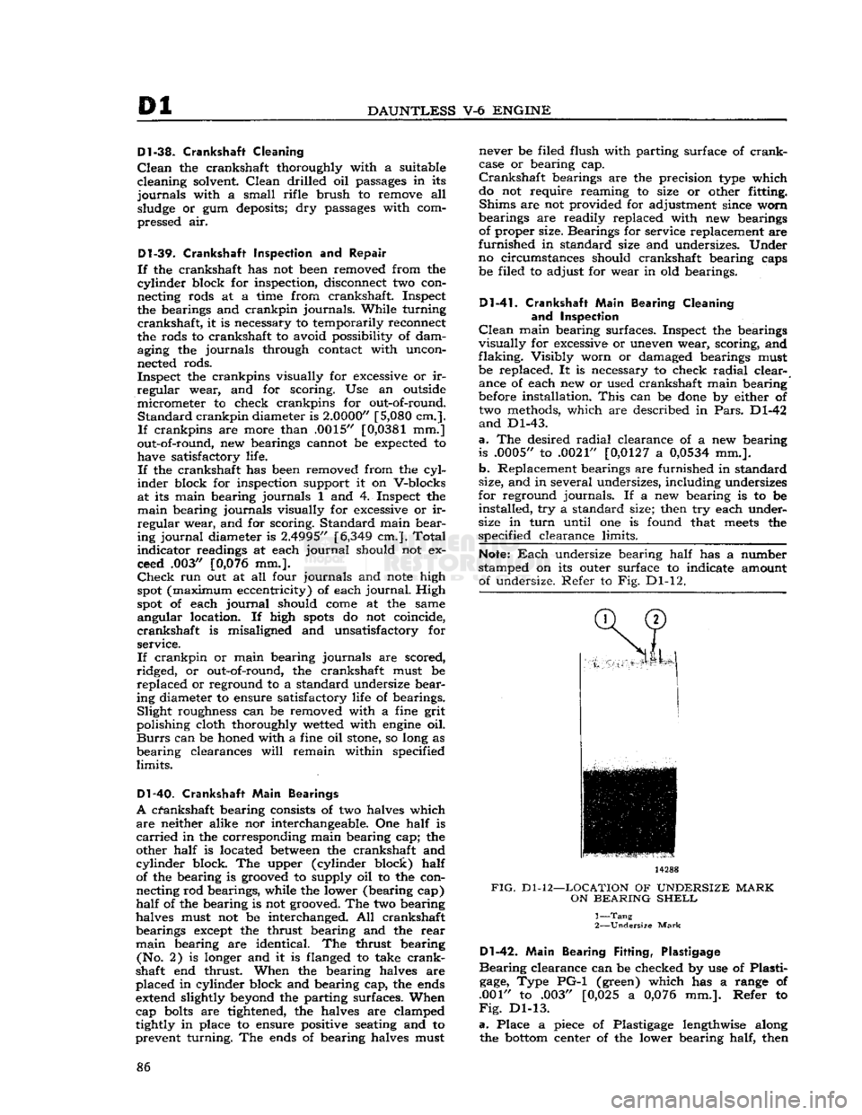
Each
undersize bearing half has a number
stamped on its outer surface to indicate amount of undersize. Refer to Fig. Dl-12. 14288
FIG.
Dl-12—LOCATION
OF
UNDERSIZE
MARK
ON
BEARING
SHELL
1—
Tang
2—
Undersize
Mark
Dl-42.
Main
Bearing
Fitting,
Plastigage
Bearing
clearance can be checked by use of Plasti
gage,
Type PG-1 (green) which has a range of
.001" to .003" [0,025 a
0,076
mm.]. Refer to
Fig.
Dl-13.
a.
Place a piece of Plastigage lengthwise along the
bottom
center of the lower bearing half, then 86
Page 94 of 376
Dl
DAUNTLESS
V-6
ENGINE
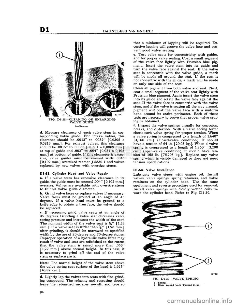
FIG.
D1-28—CLEANING
OR
ENLARGING
VALVE
GUIDE
1—Reamer
d.
Measure clearance of each valve stem in cor
responding valve guide. For intake valves, this
clearance
should be .0012" to .0032" [0,0305 a
0,0813
mm.]. For exhaust valves, this clearance should be .0015" to .0035"
[0,0381
a
0,0889
mm.]
at top of guide and .002" to .004"
[0,051
a 0,102 mm.] at bottom of guide. If this clearance is exces
sive, valve guides must be reamed with .004" [0,102 mm.] oversized reamer J-5830-1 and valves
replaced
by new valves with oversize stems.
Dl-63.
Cylinder
Head
and Valve
Repair
a.
If a valve stem has excessive clearance in its
guide, the guide must be reamed .004" [0,102 mm.]
oversize. Valves are available with oversize stems
to fit this valve guide diameter.
b.
Grind
valve faces or replace valves if necessary.
Valve
faces must be ground at an angle of 45 degrees. If a valve head must be ground to a
knife
edge
to obtain a true face, the valve should
be replaced.
c.
If necessary, grind valve seats at an angle of 45 degrees.
Grinding
a valve seat decreases valve
spring
pressure and increases the width of the seat.
The
nominal width of the valve seat is
[
1,59
mm.].
If a valve seat is wider than %" [1,98 mm.]
after grinding, it should be narrowed to specified
width
by the use of 20-degree and 70-degree stones.
Improper
operation of a hydraulic valve lifter may
result
if valve and seat are refinished to the extent
that the valve stem is raised more than .050" [1,27 mm.] above normal height. In this case, it
is necessary to grind off the end of the valve stetti or replace parts.
Note:
The normal height of the valve stem above
the valve spring seat surface of the head is
1.925"
[4,889 cm.].
d.
Lightly
lap the valves into seats with fine grind
ing compound. The refacing and reseating should
leave the refinished surfaces smooth and true so that a minimum of lapping
will
be required. Ex
cessive lapping
will
groove the valve face and pre
vent
good
valve seating.
e. Test valve seats for concentricity with guides,
and
for proper valve seating. Coat a small segment
of the valve face lightly with Prussian blue pig ment.. Insert the valve stem into its guide and
turn
the valve face against the seat. If the valve seat is concentric with the valve guide, a
mark
will
be made all around the seat. If the seat is not concentric with the guide, a
mark
will
be made
on only one side of the seat.
Clean
all pigment from both valve and seat. .Next,
coat a small segment of the valve seat lightly with
Prussian
blue pigment. Again insert the valve stem into its guide and rotate the valve face against the
seat. If the valve face is concentric with the valve
stem, and if the valve is seating all the way around,
pigment
will
coat the valve face with a uniform
band
around its entire perimeter. Both of
these
tests
are necessary to prove that proper valve seat
ing is obtained.
f. Inspect the valve springs visually for corrosion,
breaks,
and distortion.
With
a valve spring tester
check
each valve spring for proper tension. When
a
valve spring is compressed to a length of
1.640"
[4,166 cm.] (closed-valve condition), it should
have a tension of 64 lb. [29,03 kg.]. When a valve
spring
is compressed to a length of
1.260"
[3,200
cm.] (open-valve condition), it should have ten sion of 168 lb. [76,205 kg.]. Replace any valve
spring
which is visibly damaged or
does
not
meet
tension specifications.
Dl-64.
Valve Installation
Lubricate
valve stems with engine oil.
Install
valves, valve springs, spring retainers, and valve
retainers
on the cylinder head. Use the same equipment and reverse procedure used for removal.
Install
valve springs with closely wound coils to
ward
the cylinder head. Refer to Fig. Dl-29.
FIG.
Dl-29—VALVE
SPRING
1—
Spring
2—
Close
Wound
Coils
Toward
Head
94
Page 96 of 376
Dl
DAUNTLESS
V-6
ENGINE
Note:
During
engine
reassembly, use Perfect Seal
Aerosol
Spray Sealer
Part
No.
994757
on all en
gine
gaskets to ensure against vacuum, oil, gasoline
and
water leaks. Apply to head gaskets, valve covers, water pumps, oil pan gaskets, radiator and
heater
hose
connections, felt gaskets, gasoline and
oil
line connections, stud bolts, spark plug threads,
and
grease retainer washers. Refer to manufac
turer's
instructions on container for proper appli
cation procedure.
Dl-72.
Cylinder
Block
and Crankshaft
Rear
Oil Seals
Braided
fabric seals are pressed into
grooves
of
cylinder
block and
rear
main bearing cap, to
rear
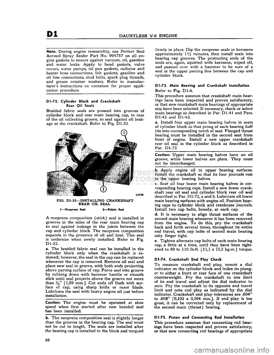
of the oil collecting groove, to seal against oil leak age at the crankshaft. Refer to Fig. Dl-32.
FIG.
Dl-32—INSTALLING
CRANKSHAFT REAR
OIL
SEAL
1—Neoprene
Seal
2—Fabric
Seal
A
neoprene composition (stick) seal is installed in
grooves
in the sides of the
rear
main bearing cap
to seal against leakage in the joints
between
the
cap and cylinder block. The neoprene composition
expands in the presence of oil and heat.
This
seal
is undersize when newly installed. Refer to Fig.
Dl-32.
a.
The braided fabric seal can be installed in the
cylinder
block only when the crankshaft is re moved; however, the seal in the cap can be replaced
whenever the cap is removed. Remove oil seal and place new seal in groove, with both ends projecting
above parting surface of cap. Force seal into
groove
by rubbing down with hammer handle or smooth
stick
until seal projects above the
groove
not more
than
[1,59 mm.]. Cut ends off flush with
sur
face of cap, using sharp knife or razor blade.
Lubricate
the seal with heavy
engine
oil just before
installation.
Caution:
The
engine
must be operated at slow
speed when first started after new braided seal
has been installed.
b. The neoprene composition seal is slightly longer
than
the
grooves
in the bearing cap. The seal must
not be cut to length. The seals are installed after the bearing cap is installed in the block and torqued
firmly
in place. Dip the neoprene seals in kerosene
approximately IV2 minutes, then install seals into
bearing cap grooves. The protruding ends of the seals are, again, squirted with kerosene, wiped off,
and
peaned over with a hammer to be sure of a
seal
at the upper parting line
between
the cap and
cylinder
block.
Dl-73.
Main
Bearing and Crankshaft
Installation
Refer
to Fig. Dl-6.
This
procedure assumes that crankshaft main bear
ings have been inspected and proven satisfactory,
or
that new crankshaft main bearings of appropriate size have been selected. If necessary, check or select
main
bearings as described in Par. Dl-41 and
Pars.
Dl-42 and Dl-43.
a.
Install
four upper main bearing halves in
seats
of cylinder block so that prong of each bearing half
fits into corresponding notch of seat. Flanged thrust
bearing must be installed in the second seat from
front of engine.
Install
a new upper crankshaft
rear
oil seal in the cylinder block as described in
Par.
Dl-72.
Caution:
Upper main bearing halves have an oil groove, while lower halves are plain. They must
not be interchanged.
b. Apply
engine
oil to upper bearing surfaces.
Install
the crankshaft so that its four journals rest
in
the upper bearing halves.
c. Seat all four lower main bearing halves in cor
responding bearing caps.
Install
a new lower
crank
shaft
rear
oil seal and cylinder block
rear
oil seal
described in
Par.
Dl-72, a and b.
Lubricate
all lower
main
bearing surfaces with
engine
oil. Position bear ing caps to cylinder block and crankcase journals.
Install
two cap bolts,
loosely,
at each cap.
d.
It is necessary to align thrust surfaces of the
second main bearing whenever it has been removed
from
the engine. To do this, pry the crankshaft
back
and forth several times, throughout its entire end travel, with cap
bolts
of second main bearing
only finger tight.
e. Tighten alternate cap
bolts
of each main bearing
cap,
a little at a time, until they have been tight ened to 80 to 110 lb-ft. [11,1 a 15,2 kg-m.] torque.
D1-74. Crankshaft End Play Check
To
measure crankshaft end play, mount a dial
indicator
on the cylinder block and index its plung
er
to either a front or
rear
face of one crankshaft
counterweight. Pry the crankshaft to one limit
of its end travel and adjust the dial indicator to
zero. Pry the crankshaft to its
opposite
end travel
limit
and
note
end play as indicated by the dial
indicator.
Crankshaft end play tolerances are .004"
to .008" [0,102 a
0,204
mm.]. If end play is too great, it can be corrected only by replacement of
the second main (thrust) bearing.
Dl-75.
Piston and Connecting Rod
Installation
This
procedure assumes that connecting rod bear ings have been inspected and proven satisfactory,
or
that new connecting rod bearings of appropriate 96
Page 106 of 376
Dl
DAUNTLESS
V-6
ENGINE
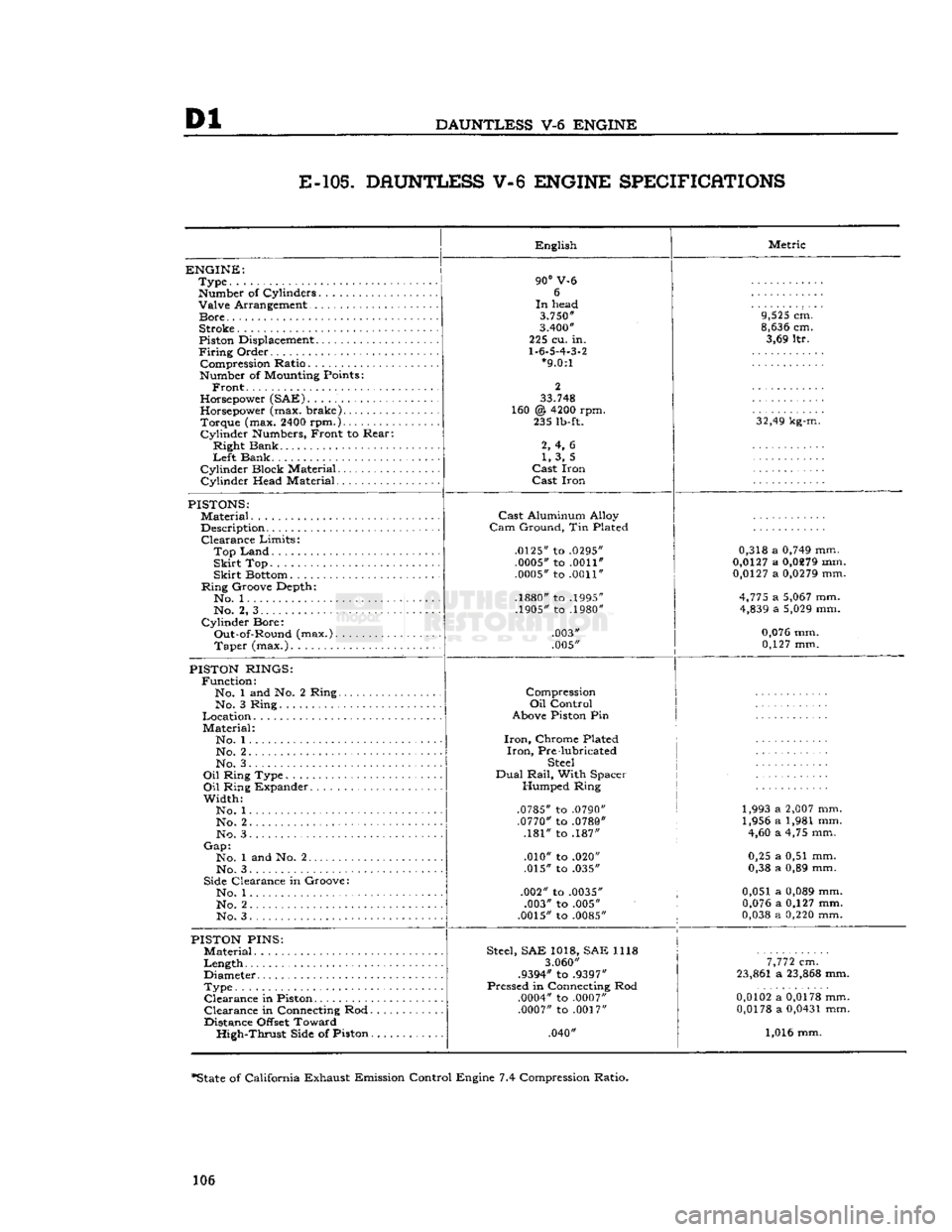
E-105.
DAUNTLESS V-6 ENGINE SPECIFICATIONS
ENGINE:
Type
Number
of Cylinders Valve Arrangement
Bore
Stroke
Piston
Displacement
Firing
Order Compression Ratio
Number
of
Mounting
Points:
Front.
Horsepower
(SAE)
Horsepower
(max. brake) Torque (max.
2400
rpm.)
Cylinder
Numbers,
Front to Rear:
Right Bank
Left
Bank
Cylinder Block Material
Cylinder Head Material English
90°
V-6 6
In
head
3.750"
3.400"
225 cu. in.
1.6.5.4.3.2
*9.0:1
2
33.748
160 @
4200
rpm. 235
lb-ft.
2, 4, 6 1, 3, 5
Cast
Iron
Cast
Iron Metric
9,525
cm.
8,636
cm. 3,69 ltr.
32,49
kg-m.
PISTONS:
Material
Description Clearance Limits:
Top
Land
Skirt
Top
Skirt
Bottom
Ring Groove Depth*. No. 1
No. 2, 3
Cylinder Bore: Out-of-Round (max.). Taper (max.)
Cast
Aluminum Alloy
Cam
Ground, Tin Plated
.0125"
to
.0295" .0005"
to
.0011"
.0005"
to
.0011"
.1880"
to
.1995"
.1905"
to
.1980"
.003"
.005" 0,318 a
0,749
mm.
0,0127
a
0,0279
mm.
0,0127
a
0,0279
mm.
4,775
a
5,067
mm.
4,839
a
5,029
mm.
0,076
mm. 0,127 mm.
PISTON
RINGS:
Function: No. 1 and No. 2 Ring.. No. 3 Ring
Location
Material: No. 1...
No. 2 No. 3.
Oil
Ring Type
Oil
Ring Expander
Width: No. 1
No. 2. .
No. 3
Gap:
No. 1 and No. 2
No. 3
Side
Clearance in Groove: No. 1
No. 2
No. 3 Compression
Oil
Control
Above
Piston
Pin
Iron,
Chrome Plated
Iron,
Pre lubricated
Steel
Dual
Rail,
With Spacer Humped Ring
.0785"
to
.0790" .0770"
to
.0780"
.181" to .187"
.010" to .020"
.015" to .035"
.002" to
.0035"
.003" to .005"
.0015"
to
.0085"
1,993 a
2,007
mm.
1,956 a 1,981 mm. 4,60 a 4,75 mm.
0,25 a 0,51 mm.
0,38 a 0,89 mm.
0,051 a
0,089
mm.
0,076
a 0,127 mm.
0,038
a
0,220
mm.
PISTON
PINS:
Material
Length
Diameter
Type Clearance in
Piston
Clearance in
Connecting
Rod.
Distance
Offset
Toward High-Thrust
Side
of Piston.
Steel,
SAE 1018, SAE 1118
3.060"
.9394"
to
.9397"
Pressed in
Connecting
Rod
.0004"
to
.0007" .0007"
to
.0017"
.040"
7,772
cm.
23,861
a
23,868
mm.
0,0102
a
0,0178
mm.
0,0178
a
0,0431
mm.
1,016 mm.
*State
of California Exhaust Emission Control Engine 7.4 Compression Ratio.
106