length JEEP CJ 1953 Owner's Guide
[x] Cancel search | Manufacturer: JEEP, Model Year: 1953, Model line: CJ, Model: JEEP CJ 1953Pages: 376, PDF Size: 19.96 MB
Page 192 of 376
H
ELECTRICAL
SYSTEM
Regulator
ground screw to battery ground post
—.03-volt maximum.
Generator
frame to battery ground post—.03-volt
maximum.
H-47.
Test Procedure
a.
Circuit
Breaker—Connect
an ammeter in series between the regulator B-terminal and the lead
wire
removed from that terminal. Connect a
voltmeter between the regulator
A-terminal
and the regulator mounting base. Disconnect the field lead
from
the regulator
F-terminal
and insert a variable resistance (3 amp., 50 ohm capacity) between the
lead
and the regulator terminal. Run the generator
at about 1000 generator rpm. Insert all the re
sistance in the field
circuit,
then slowly reduce the
resistance noting the voltage reading just before the change caused by the closing of the circuit
breaker.
Increase the charging rate to the figure
specified for the regulator being tested then reduce
the charging rate by inserting resistance in the
field
circuit.
Note
the voltmeter and ammeter
reading
just before the circuit breaker
opens
and
the ammeter reading drops to zero. The closing voltage and the opening voltage or current should
be within the limits specified. An accurate method
for noting the exact instant of the opening or closing
of the circuit breaker is to connect a headphone (2000 ohms or higher) to the battery and armature
terminals
of the regulator. When the contacts
open or close a
click
will
be
heard
in the headphones.
To
adjust the closing voltage change the armature
spring
tension by bending the hanger at the lower end of the spring. Increase the spring tension to
raise
the closing voltage or decrease the tension
to lower the closing voltage. To adjust the opening voltage raise or lower the stationary contact
keeping the contacts perfectly aligned. Increasing
the contact gap lowers the opening
'
voltage.
Change
the contact gap by expanding or contract
ing the stationary contact bracket, keeping the
contacts aligned. Do not adjust the gap between
the contacts to less than the specified minimum.
b.
Voltage Regulator—Connect the ammeter as in
step
a. Connect the voltmeter between the regulator
B-terminal
and the regulator base. Remove the
variable
resistance from the field
circuit.
Run the
generator at
half
output for 15 minutes to bring
the regulator to normal operating temperature.
Keep
the cover on the regulator during the
warm-
up period and also when taking readings.
Stop the engine then bring it up to approximately 2500 generator rpm. Adjust the amperage to
half
maximum
output by turning on lights or accessor
ies and then
note
the voltmeter reading.
This
read
ing should be within the limits specified for the voltage regulator operation. To adjust the oper
ating voltage change the
armature
spring tension by
bending the hanger at the lower end of the
arma
ture
spring. After each adjustment
stop
the engine then restart it.
Bring
it up to speed and adjust the
current
before taking a reading. In order to obtain
an
accurate indication of the operation of the volt
age regulator unit connect a headphone (2000 ohm
or
higher) between the
F-terminal
and ground to
pick
up the sound of the opening and closing of the
contacts. The clicks should be regular and clear without irregularities or missing. If the
tone
is not
clear
and regular remove the regulator cover and
inspect the contacts. The contacts should be flat
and
not burned excessively and should be aligned
to make
full
face contact. If the contacts need
cleaning refer to paragraph d for the method.
c.
Current
Regulator—Connect the regulator and the
test
equipment as in
step
b. Running the generator at approximately 3000 generator rpm.,
turn
on lights and accessories so that the generator must charge at maximum rate. The ammeter should give a reading within the limits specified.
To
adjust opening amperage, change the armature
spring
tension by bending the hanger at the lower
end of the armature spring. After each adjustment,
stop
the engine, then restart it.
Bring
the engine up to speed and take an ammeter reading. Keep
the cover on the regulator when taking
these
readings.
Connect
a headphone (2000 ohms or higher) be
tween the regulator
F-terminal
and ground to pick
up the sound of opening and closing of the contacts.
Clear,
regular clicks should be heard over the
headphones; they should not be
irregular
or missing.
If
the
tone
is not clear and regular remove the
regulator cover and inspect the contacts. The
contacts should be flat and not burned excessively
and
should be aligned to make
full
face contact. If
the contacts need cleaning refer to paragraph d.
below for the method.
d.
Contacts—Inspect the contacts on all three
units.
In normal use the contacts
will
become
grayed.
If the contacts are burned or dirty or if they are not smooth, file the contacts with a #6
American,
Swiss cut, equalling file. Move the file
parallel
and lengthwise to the armature.
File
just
enough so that the contacts present a smooth
sur
face toward each other. It is not necessary to remove every trace of pitting. After filing, dampen
a
piece of linen or lintless bond tape in refined
carbon
tetrachloride and draw the tape between
the contacts. Repeat with a dry piece of tape. Use
clean
tape for each set of contacts.
e. Recheck—Operate the unit at
half
maximum
output for five minutes with the cover on the regu
lator.
Repeat the testing procedure for all units as described in a, b, c above. Be sure cover is on regu
lator
when taking readings.
H-48.
Quick
Checks
H-49.
Low Charging Rate with a
Fully
Charged
Battery
A
fully charged battery and a low charging rate
indicates normal regulator operation.
A
further check of the regulator operation can be
made by using the starting motor for 5 to 10
seconds with the ignition switch in the "off" posi tion.
Then
start the engine and operate at a genera
tor speed of 2500 to 3000 rpm. The charging rate should rise to its maximum value then taper off to
a
minimum charge as the battery becomes charged.
H-50.
High Charging Rate with a
Fully
Charged
Battery
This
is usually an indication that the voltage regu
lator
is not operating correctly. The high voltage 192
Page 193 of 376
'Jeep1
UNIVERSAL
SERIES SERVICE
MANUAL
H
will
cause the battery to gas excessively and
will
shorten the life of the ignition contacts and, in
general,
will
have a detrimental
effect
on all con
nected load.
Connect
an ammeter in series with the regulator
"B"
terminal and the lead removed from the termi
nal.
Run the generator at a medium speed and per
form
the following operation. After each
test
is
completed reconnect whatever leads have been opened.
H-51.
Test One
Disconnect the field lead at the generator.
a.
Output drops to zero—shorted field circuit in regulator or in wiring harness. See
test
2.
b.
Output
does
not drop—shorted field circuit in
generator. Inspect generator.
H-52.
Test Two
Disconnect the field lead at the regulator.
a.
Output drops to zero—shorted field in regulator.
See
test
3.
b.
Output
does
not drop—shorted wiring harness.
Repair
or replace wiring harness.
H-53.
Test
Three
Remove the regulator cover and hold the
voltage
regulator contacts open.
a.
Output drops to zero—regulator contacts stick
ing,
regulator out of adjustment, or regulator in operative.
Check
operation
(test
5), check for high
resistance
(test
4), and clean contacts per instruc
tions in Par. H-56.
b.
Output
does
not drop—shorted field circuit in
the regulator.
Clean
the regulator contacts and in spect the regulator visually for incorrect wiring be
tween units and shorted leads.
H-54.
Test
Four
Operate
the units at 10 amperes output and meas
ure
the
voltage
drop from the regulator base to
the generator frame.
a.
Voltage reading below .03 volts—ground
cir
cuit
is satisfactory. See
test
5.
b.
Voltage reading above .03 volts—Inspect ground
circuit
for poor connections and eliminate the high
resistance. See
test
5.
H-56.
Test
Five
Connect
a headphone from the regulator field ter
minal
to the base and hold the current regulator
contacts closed.
a.
A steady beat is heard—voltage regulator oper
ating.
Reset regulator as in the operation
test,
Par.
H-47.
b.
An unsteady beat is heard—dirty or sticking
contacts.
Clean
contacts per instructions in Par.
H-56.
c.
No beat is heard—inoperative
voltage
regulator
unit.
Adjust regulator operation as in the operation
test.
If the regulator cannot be adjusted within
limits,
remove for overhaul.
H-56.
Cleaning of Contacts
Clean
the
voltage
regulator contacts with a #6
American
Swiss cut equalling file.
File
lengthwise
and
parallel to the armature and then clean the
contacts with clean linen tape.
First
draw a piece
of tape that has been wet with carbon tetrachlor
ide
between
the contacts then follow with dry tape. Reset the regulator operation as in the oper
ation
test,
Par. H-47.
H-57.
Low Battery and a Low or No Charging Rate
Check
all wiring for
loose
connections, frayed in
sulation and high resistance connections and cor
rect
any fault.
Make
sure the generator operates correctly with
out the regulator in the
circuit.
Remove the "A"
and
"B" leads from the regulator and connect an
ammeter
between
them. Remove the field lead from
the regulator and while operating at idle speed
touch the field lead to the regulator base. Increase
the speed slowly noting the charging rate. Do not
increase
the output above the rated output of the generator. If the generator output
will
not build
up,
inspect the wiring harness for shorts and
opens
and
remove the generator for an overhaul.
Connect
an ammeter
between
the battery lead and
the regulator
"B"
terminal. Connect the field lead to the regulator "F" terminal and connect the
armature
lead to the regulator
"A"
terminal.
Con
nect a voltmeter from the regulator
"A"
terminal to
the regulator base. Operate the generator at a medium speed and perform the following
tests:
H-58.
Test Six
Read
the voltmeter.
a.
Voltage builds up—open series
circuit.
See
test
7.
b.
Voltage
does
not build up—regulator out of ad
justment, field circuit open, grounded series
circuit.
See
test
8.
H-59.
Test Seven
Remove the regulator cover and with the generator
operating at a medium speed hold the circuit
breaker
contacts closed.
a.
Ammeter shows no charge—open
circuit
breaker
shunt winding, incorrect setting of circuit breaker,
or
dirty contacts.
Clean
contacts and reset circuit
breaker
as in
Par.
H-47d. If the circuit breaker
can
not be set, the shunt coil is open and the regulator
should be removed for overhaul.
b.
No generator output—clean the circuit breaker
contacts and try the
test
again. If there is
still
no
charge the series windings are open and the regu
lator
should be removed for overhaul.
H-60.
Test
Eight
Run
the generator at idle speed and momentarily
connect a jumper from the
F-terminal
to the regu
lator
base.
a.
Voltage builds up—open field circuit or regula
tor out of adjustment. See
test
9.
b.
Voltage
does
not build up—grounded series
cir
cuit.
Remove regulator for overhaul. 193
Page 206 of 376
H
ELECTRICAL
SYSTEM
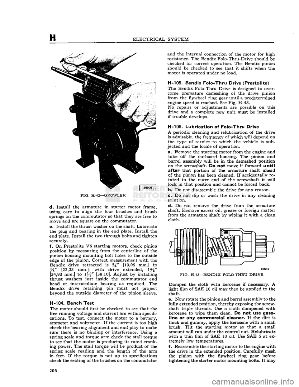
FIG.
H-42—GROWLER
d.
Install
the armature in starter motor frame,
using care to align the four brushes and brush
springs on the commutator so that they are free to
move
and are square on the commutator.
e.
Install
the thrust washer on the shaft.
Lubricate
the plug and bearing in the end plate.
Install
the
end plate.
Install
the two through
bolts
and tighten securely.
f.
On Prestolite V6 starting motors, check pinion position by measuring from the centerline of the
pinion housing mounting bolt
holes
to the outside
edge
of the pinion.
Correct
measurement with the
Bendix
drive retracted is [19,05 mm.] to
%"
[22,23 mm.]; with drive extended, 1%"
[34,93
mm.] to 1^" [38,10]. Adjust by installing
thrust
washers just inside the commutator end
head or intermediate bearing as required. The
Bendix
drive retaining pin must not project
beyond the outside diameter of the pinion
sleeve.
H-104.
Bench Test
The
motor should first be checked to see that the
free running
voltage
and current are within specifi cations. To
test,
connect the motor to a battery,
ammeter and voltmeter. If the current is too high
check
the bearing alignment and end play to make
sure
there is no binding or interference. Using a
spring
scale and torque arm check the stall torque to see that the motor is producing its rated
crank
ing power. The stall torque
will
be product of the
spring
scale reading and the length of the arm
in
feet.
If the torque is not up to specifications
check
the seating of the brushes on the commutator
and
the internal connection of the motor for high
resistance. The Bendix
Folo-Thru-Drive
should be checked for correct operation. The Bendix pinion
should be checked to see that it shifts when the motor is operated under no load.
H-105.
Bendix Folo-Thru Drive (Prestolite)
The
Bendix
Folo-Thru
Drive is designed to over
come
premature demeshing of the drive pinion
from
the flywheel ring gear until a predetermined
engine
speed is reached. See Fig. H-43. No repairs or adjustments are possible on this
drive
and a
complete
new unit must be installed
if
trouble develops.
H-106.
Lubrication
of
Folo-Thru Drive
A
periodic cleaning and relubrication of the drive is advisable, the frequency of which
will
depend on
the type of service to which the vehicle is sub
jected and the locale of operation.
a.
Remove the starting motor from the
engine
and take off the outboard housing. The pinion and
barrel
assembly
will
be in the demeshed position
on the screwshaft. Do not
move
it forward
until
after
that portion of the armature shaft ahead
of the pinion has been cleaned. If accidentally ro
tated to the outer end of the screwshaft it
will
lock
in that position and cannot be forced back.
b.
Do not disassemble the drive for any reason.
c.
Do not dip or wash the drive in any cleaning solution.
d.
Do not remove the drive from the armature
shaft. Remove
excess
oil, grease or foreign matter
from
the armature shaft by wiping it with a clean cloth.
3
10859
FIG.
H-43—BENDIX
FOLO-THRU DRIVE
Dampen
the cloth with kerosene if necessary. A
light film of
SAE
10 oil may then be applied to the shaft.
e.
Now rotate the pinion and
barrel
assembly to the
fully
extended position, thereby exposing the screw shaft triple threads. Use a cloth dampened with
kerosene to wipe them clean. Do not use
gaso
line
or any
commercial cleaner.
If the dirt is
thick
and gummy, apply the kerosene with a small
brush.
Tilt
the starting motor so that a small
amount
will
run under the control nut. Relubricate
with
a thin film of
SAE
10 oil. Use SAE 5 at ex tremely low temperatures.
f.
Reassemble the starting motor to the
engine
with the drive in the extended position.
Carefully
mesh the pinion with the flywheel ring gear before
tightening the starter motor mounting bolts. It may 206
Page 209 of 376
'Jeep'
UNIVERSAL
SERIES SERVICE
MANUAL
H
H-111.
Brushes
Check
brush length. If brushes are worn to one-
half
their original length, replace them. Also check
for
cracks,
chips, damaged mounting holes, oil
saturation,
or other damage; replace brushes.
H-112.
Commutator
Check
the commutator for wear and discoloration.
If
the commutator is rough or worn the armature
should be removed and the commutator turned
down in a lathe. A discolored commutator should
be cleaned with carbon tetrachloride and inspected.
Scratches
on the commutator may be removed
with
sand paper. Use compressed air to remove
sand
particles after cleaning.
H-113.
Armature
Visually
inspect the armature for mechanical
defects
before checking for shorted or grounded
coils. Use a set of
test
probes for testing armature
circuits.
To
test
the armature for grounds, touch
one point of the
test
probes to a commutator
seg
ment and touch the other point to the core or shaft.
Do not touch the points to the bearing surface or
to the brush surface as the arc formed
will
burn
the smooth finish. If the lamp lights, the coil con
nected to the commutator
segment
is grounded.
H-114.
Field
Coils
Using
test
probes, check the field coils for both ground and open circuits. To
test
for ground, place
one probe on the motor frame or
pole
piece and
touch the other probe to the field coil terminals.
If
a ground is present, the lamp
will
light.
To
test
for open circuits, place the probes on the
field coil terminal and on an insulated
brush.
If
the light
does
not light, the coil is open circuited.
H-115.
Brush
Holder Inspection
Inspect
brush
holders for distortion, wear, and other
damage.
Check
that brush holders pivot freely on
their
pivot pins.
Check
brush spring tension with
a
spring scale. Hook the spring scale under the
brush
holder at the brush and
pull
on a line
paral
lel
to the side of the
brush.
Note
scale reading just
as brush leaves commutator. Tension must be 35 oz. [9,925 kg.] minimum. Replace brush springs
if
tension is insufficient.
H-116.
Solenoid
Coils
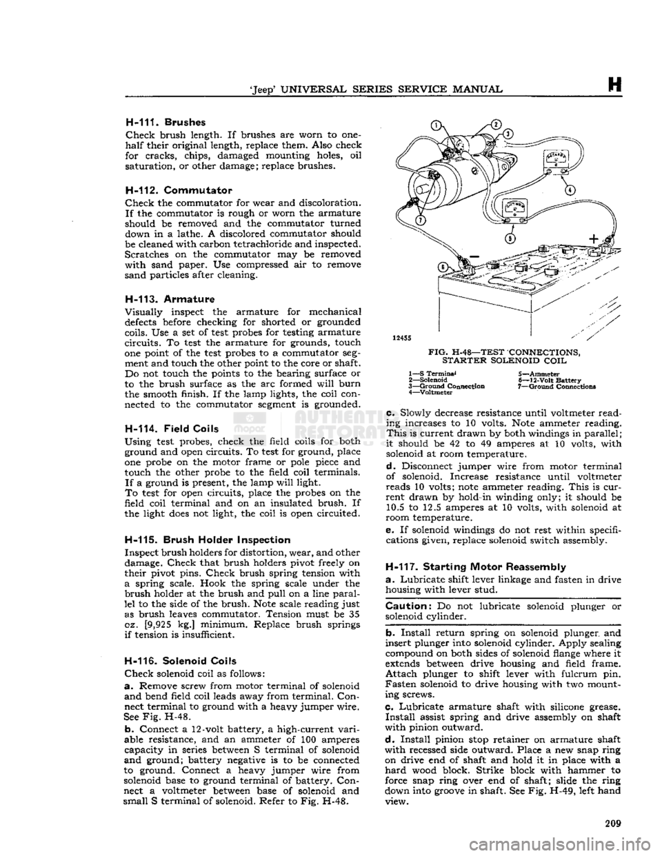
Check
solenoid coil as follows:
a.
Remove screw from motor terminal of solenoid
and
bend field coil leads away from terminal.
Con
nect terminal to ground with a heavy jumper wire.
See
Fig.
H-48.
b.
Connect a 12-volt battery, a high-current
vari
able resistance, and an ammeter of 100 amperes
capacity
in series
between
S terminal of solenoid
and
ground; battery negative is to be connected
to ground. Connect a heavy jumper wire from
solenoid base to ground terminal of battery.
Con
nect a voltmeter
between
base of solenoid and
small
S terminal of solenoid. Refer to Fig. H-48.
12455
FIG.
H-48—TEST CONNECTIONS,
STARTER
SOLENOID
COIL
1— S
Terminal
2—
Solenoid
3—
Ground
Connection 4—Voltmeter 5—Ammeter
6—
12-Volt
Battery
7—
Ground
Connection*
c.
Slowly decrease resistance until voltmeter
read
ing increases to 10 volts.
Note
ammeter reading.
This
is current drawn by both windings in
parallel
;
it
should be 42 to 49 amperes at 10 volts, with solenoid at room temperature.
d.
Disconnect jumper wire from motor terminal
of solenoid. Increase resistance until voltmeter
reads
10 volts;
note
ammeter reading.
This
is
cur
rent
drawn by hold-in winding only; it should be 10.5 to 12.5 amperes at 10 volts, with solenoid at
room temperature.
e. If solenoid windings do not rest within specifi cations given, replace solenoid switch assembly.
H-117.
Starting Motor Reassembly
a.
Lubricate
shift lever linkage and fasten in drive housing with lever stud.
Caution:
Do not lubricate solenoid plunger or solenoid cylinder.
b.
Install
return spring on solenoid plunger and
insert
plunger into solenoid cylinder. Apply sealing
compound on both sides of solenoid flange where it
extends
between
drive housing and field frame.
Attach
plunger to shift lever with fulcrum pin.
Fasten
solenoid to drive housing with two mount
ing screws.
c.
Lubricate
armature shaft with silicone grease.
Install
assist spring and drive assembly on shaft
with
pinion outward.
d.
Install
pinion
stop
retainer on armature shaft
with
recessed side outward. Place a new snap ring on drive end of shaft and hold it in place with a
hard
wood block. Strike block with hammer to
force snap ring over end of shaft; slide the ring
down into
groove
in shaft. See Fig. H-49, left hand view. 209
Page 226 of 376
![JEEP CJ 1953 Owners Guide
I
CLUTCH 1-1.
GENERAL
The
clutch on current Jeep vehicles is either
Auburn
or Borg and Beck manufactured. Vehicles
equipped with F4-134
engines
have an
Auburn
9.25" [23,4 cm.] single JEEP CJ 1953 Owners Guide
I
CLUTCH 1-1.
GENERAL
The
clutch on current Jeep vehicles is either
Auburn
or Borg and Beck manufactured. Vehicles
equipped with F4-134
engines
have an
Auburn
9.25" [23,4 cm.] single](/img/16/57040/w960_57040-225.png)
I
CLUTCH 1-1.
GENERAL
The
clutch on current 'Jeep' vehicles is either
Auburn
or Borg and Beck manufactured. Vehicles
equipped with F4-134
engines
have an
Auburn
9.25" [23,4 cm.] single plate dry-disc clutch. The
pressure plate has three coil pressure springs and
three levers or fingers.
The
V6-225
engine
is equipped with a 10.4" [26,4
cm.] Borg and Beck single plate dry-disc clutch.
The
pressure plate utilizes either a finger-type
diaphragm spring, or a coil
type
spring pressure plate for clutch release.
The
driven plates of all
models
are built with
vibra
tion damper springs and have two flexible facings
which
provide
smooth
engagement
of the
engine
power.
Early
'Jeep' vehicles equipped with a Dauntless
V-6
engine
use a 10.4" [26,4 cm.] single plate, dry-
disc clutch, incorporating a diaphram-type spring assembly.
The
clutch is of the centrifugal single dry disc
type
and
consists of the clutch disc, pressure plate and
the clutch release bearing.
The
clutch is actuated by a clutch pedal and a
series of mechanical linkage.
When
the clutch pedal is in the
engaged
position,
the clutch disc facings are clamped
between
the
friction surface of the
engine
flywheel and the face of the clutch pressure plate, thereby connect
ing
engine
power to the transmission. Depressing
the clutch pedal actuates the clutch release shaft
fork
which
moves
the clutch release bearing against
the clutch fingers.
This,
in
turn,
moves
the pressure
plate away from the clutch disc. Since the disc is splined to the transmission input shaft, the clutch
disc and transmission input shaft
will
stop
when
the clutch is disengaged, thereby disconnecting
engine
power from the transmission.
1-2.
Clutch
Maintenance
To
obtain normal life and satisfactory performance
from any clutch it must be correctly operated and
properly maintained. Two conditions which shorten
clutch life are continuous operation of the clutch
release bearing and clutch slippage.
The
clutch release bearing is
designed
for inter
mittent use. If run continuously the bearing
lubri
cant
will
become
exhausted causing the bearing to
become
dry, noisy, or
will
seize, resulting in clutch
finger or diaphragm wear. The clutch must be properly adjusted so that the release bearing is
free of the clutch fingers or diaphragm at all times,
except
when the clutch pedal is depressed.
Excessive
clutch slippage
often
occurs when the
vehicle is overloaded, the vehicle load is applied
too quickly, or when the pressure of the clutch fingers or diaphragm is only partially applied to the clutch plate.
Friction
between
the clutch facing
and
flywheel produces
excessive
heat causing
burned,
glazed and worn linings, resulting in shortened clutch life. Avoid clutch slippage under
heavy loads by using a lower gear or reducing the load.
1-3.
Clutch
Pedal
Linkage
and Adjustment
Adjust
the clutch pedal free travel whenever the clutch
does
not
disengage
properly, or when new
clutch parts are installed. Improper adjustment of
the clutch pedal free travel is one of the
most
fre
quent causes of clutch failure and can be a con tributing factor in
some
transmission failures.
As
the clutch facings wear the free travel of the clutch pedal diminishes. When sufficient wear oc
curs
the pedal clearance must be adjusted.
Two
types
of clutch linkage have
been
used on Jeep vehicles, a cross shaft
tube
and lever
type
shown in Fig. 1-1, and a clutch control cable
type
shown in Fig. 1-2. The clutch pedal adjustment
procedures for both
type
linkages are as follows.
•
Cross
Shaft
Lever
and Tube Type
Refer
to Fig. 1-1.
Note:
Two different
Clutch
Control
Lever
and
Tube
Assemblies have
been
installed on 'Jeep*
Universal
vehicles equipped with a V-6
engine
and
T14A
transmission.
Should difficulty in shifting the transmission be
noted, check the length of the clutch release pedal
rod,
item (16) in Fig. 1-1. Measure the distance
between
the centerlines of the cotter key holes.
FIG.
1-2—CLUTCH
LINKAGE AND
ADJUSTMENT,
CONTROL
CABLE TYPE
A—Top
View,
Cable
to
Clutch
Fork
1—
Retracting
Spring
(Clutch
Fork)
2—
Clutch
Fork
3—
Ball
Adjusting Nut
4—
Lock
Nut 5—
Clutch
Cable
B—Side
View,
Cable
to
Clutch
Pedal 6—
Clutch
Cable
Support
Bracket
7—
Clutch
Cable
Housing
8—
Anchor
Bracket-to-Frame Side
Rail
9—
Retracting
Spring
(Clutch
Pedal)
10—Clutch
Pedal Assembly
*
© © ©
1437S
226
Page 227 of 376
![JEEP CJ 1953 Owners Guide
Jeep
UNIVERSAL SERIES SERVICE
MANUAL
The
correct distance should be 10%"
[26,04
cm.].
If
the length of the clutch release pedal rod is
other than
10
W
[26,04
cm.], the vheicle is eq JEEP CJ 1953 Owners Guide
Jeep
UNIVERSAL SERIES SERVICE
MANUAL
The
correct distance should be 10%"
[26,04
cm.].
If
the length of the clutch release pedal rod is
other than
10
W
[26,04
cm.], the vheicle is eq](/img/16/57040/w960_57040-226.png)
'Jeep'
UNIVERSAL SERIES SERVICE
MANUAL
The
correct distance should be 10%"
[26,04
cm.].
If
the length of the clutch release pedal rod is
other than
10
W
[26,04
cm.], the vheicle is equipped with the early
type
Clutch
Control
Lever
and
Tube Assembly, which should be removed, and^trie latest
designed
parts should be installed.
The
free pedal clearance is adjusted by lengthening
or shortening the" clutch fork cable. To make this adjustment,
loosen
the jam nut on the cable clevis
and
lengthen or shorten the cable to obtain %"
[19,05
mm.] free travel at the pedal pad, then
tighten the jam unit.
•
Clutch
Control Cable Type
Refer
to Fig. 1-2.
a.
With the clutch pedal pad against the floor
panel, (pedal up, clutch
engaged)
adjust ball ad
justing nut until slack is removed from the cable
and
the clutch throwout bearing contacts the clutch
pressure plate, release levers or diaphragm plate.
b. Back-off ball adjusting nut 2
V2
turns to obtain
approximately %"
[19,05
mm.] free travel.
Lock
hex nut.
FIG.
1-3—AUBURN
CLUTCH
ASSEMBLY —
HURRICANE F4 ENGINE 1—
Driven
Plate and Hub
2—
Pressure
Plate
3—
Pivot Pin
4—
Bracket
5—
Spring
Cup 6—
Pressure
Spring 7— Release
Lever
8—
Return
Spring
9—
Adjusting
Screw
10—
Jam
Nut 11—
Washer
Note:
Some older 'Jeep' vehicles may
develop
side
movement
of the clutch and brake pedals resulting
from wear of the pedals, shafts, and bushings. One way to
compensate
for this wear is to install a pedal
slack
adjuster kit 1-4.
CLUTCH
—
HURRICANE
F4
ENGINE
•
Auburn
Vehicles equipped with the Hurricane F4
engine
have a 9.25" [23,4 cm.] driven plate. The auburn clutch driving (pressure) plate assembly (Fig. 1-3)
has three pressure springs and three levers or
fingers.
1-5.
Clutch
Removal
When
necessary to remove the clutch,
follow
the procedures outlined in Section J for the removal
of the transmission and transfer case from the vehicle. Then remove the flywheel housing and use
the following procedures for removing the clutch assembly.
Note:
The F4
engine
may be removed from the
vehicle when inspecting or replacing the clutch.
Refer
to Section D for Hurricane F4
engine
removal and then
follow
the instructions given
below
to remove the clutch assembly.
a.
Mark
the clutch pressure plate and
engine
fly
wheel with a center punch so the clutch assembly
may be installed in the same position after adjust
ments
or replacement are completed.
b. Remove the clutch pressure plate bracket
bolts
equally, a little at a time, to prevent distortion and
to relieve the clutch springs evenly.
c. Remove the pressure plate assembly and driven
plate from the flywheel.
1-6.
Clutch
Pressure Plate and Disc Inspection
Inspect the pressure plate face for
cracks,
chips,
and
warpage.
Check
the pressure plate levers for
excessive
wear and the springs for breaks. If any of the
above
conditions exist, the
complete
pressure
plate must be replaced.
Check
the clutch disc for
excessive
wear,
loose
or damaged facings, broken
vibration damper springs and evidence of grease
or oil. If any of the
above
conditions exist, replace
the clutch disc.
1-7.
Clutch
Pressure Plate Adjustment —
Auburn
The
clutch pressure plate must be checked
before
installing a new or reconditioned clutch. The proper 11339
FIG.
1-4—CHECKING
AUBURN
CLUTCH
LEVER
ADJUSTMENT
1— Adjustment Gauge
2—
Fixture
Mounting Bolt
3—
Clutch
Fixture
227
Page 228 of 376
CLUTCH
©—*
11378
FIG.
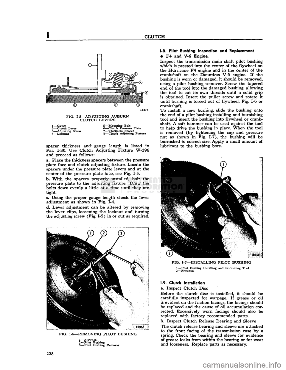
1-5—ADJUSTING
AUBURN
CLUTCH
LEVERS
1—
Gauge
5—Mounting Bolt
2—
Clutch
Lever
6—Clutch
Pressure
Plate
3—
Adjusting
Screw
7—Thickness
Spacer
4—
Locknut
8—Clutch
Adjusting
Fixture
spacer thickness and
gauge
length is listed in
Par.
1-30. Use
Clutch
Adjusting Fixture W-296
and
proceed as follows:
a.
Place the thickness spacers
between
the pressure
plate face and clutch adjusting fixture. Locate the spacers under the pressure plate levers and at the
center of the pressure plate face, see Fig. 1-5.
b. With the spacers properly installed, bolt the
pressure plate to the adjusting fixture.
Draw
the
bolts
down evenly a little at a time until they are
tight.
c. Using the proper
gauge
length check the lever adjustment as shown in Fig. 1-4.
d.
Lever
adjustment can be altered by removing
the lever clips, loosening the locknut and turning
the adjusting screw (Fig. 1-5) in or out as required.
FIG.
1-6—REMOVING
PILOT
BUSHING
1—
Flywheel
2—
Pilot
Bushing
3—
Pilot
Bushing Remover 1-8. Pilot Bushing Inspection and Replacement
•
F4 and V-6 Engine.
Inspect the transmission main shaft pilot bushing
which
is pressed into the center of the flywheel on
the Hurricane F4
engine
and in the center of the
crankshaft
on the Dauntless V-6 engine. If the bushing is worn or damaged, it should be removed,
using a pilot bushing remover. Screw the tapered end of the tool into the damaged bushing, allowing
the tool to cut its own threads until a solid grip is obtained. Insert the puller screw and rotate it
until
bushing is forced out of flywheel, Fig. 1-6 or
crankshaft.
To
install a new bushing, slide the bushing
onto
the end of a pilot bushing installing and burnishing tool and insert the bushing into flywheel or
crank
shaft. A
soft
hammer can be used against the tool
to help drive the bushing in place. When the tool
is removed (by tightening the cap and pressure
nut as shown in Fig. 1-7), the bushing
will
be
burnished
to correct size. Apply a small amount of
lubricant
to the bushing bore.
FIG.
1-7—INSTALLING
PILOT
BUSHING
1—
Pilot
Bushing
Installing
and
Burnishing
Tool
2—
Flywheel
1-9.
Clutch
Installation
a.
Inspect
Clutch
Disc
Before the clutch disc is installed, it should be
carefully
inspected for warpage. If grease or oil is evident on the friction facings, the facings should
be replaced and the cause of oil accumulation cor rected. Excessively worn facings should also be
replaced with factory recommended parts.
b. Inspect
Clutch
Release Bearing and Sleeve
The
clutch release bearing and
sleeve
are attached to the front facing of the transmission case by a
spring.
Check
the bearing and
sleeve
for evidence
of grease leaks from within the bearing or for wear
and
looseness.
Replace parts as necessary. 228
Page 230 of 376
CLUTCH
is deeply scored or grooved, the part should be
replaced.
b. Inspect driven plate for wear or damage to fac
ings,
loose
rivets, broken or
loose
torsion springs,
and
flattened cushion springs. If facings are worn
near
rivets or are oily, replace the plate assembly.
A
slight amount of oil on clutch facings
will
cause
clutch
grab and chatter; excessive oil on facings
will
cause slippage. It is not practical to remove
oil
with solvents or by buffing since oil
will
con
tinue to bleed from facing material when hot. If
oil
is found on driven plate facings, examine trans
mission drainback hole, pilot bushing,
engine
rear
main
bearing and other points of possible oil leakage. Test the fit of driven plate hub on trans
mission main drive gear for an easy sliding fit.
c. Inspect clutch release bearing for scoring or ex cessive wear on front contact face. Test for rough
ness
of balls and races by pressing and turning
front race slowly. Inspect main drive gear pilot
bushing in crankshaft. Replace bushing if it is rough or worn. Regardless of whether the old plate
or
a new plate is to be installed, check the plate
for runout. Slide the driven plate, front side first,
over the transmission main drive gear shaft so that
it
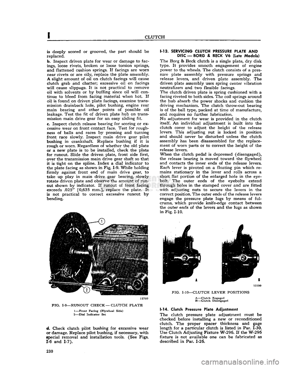
is tight on the spline. Index a
dial
indicator to the plate facing as shown in
Fig.
1-9. While holding
firmly
against front end of main drive gear, to take up play in main drive gear bearing, slowly
rotate driven plate and observe the amount of
run
out shown by indicator. If runout of front facing
exceeds
.025" [0,635 mm.], replace the plate. It
is not practical to correct excessive runout by bending. 12769
FIG.
1-9—RUNOUT
CHECK
—
CLUTCH
PLATE
1—
Front
Facing
(Flywheel
Side)
2—
Dial
Indicator
Set
d.
Check
clutch pilot bushing for excessive wear
or
damage. Replace pilot bushing, if necessary, with
special
removal and installation
tools.
(See
Figs.
1-6 and 1-7). 1-13.
SERVICING
CLUTCH
PRESSURE
PLATE
AND
DISC
—
BORG
&
BECK
V6
(Late
Models)
The
Borg & Beck clutch is a single plate, dry disk
type. It provides smooth
engagement
of
engine
power to the wheels. The clutch consists of a pres
sure
plate assembly with pressure springs and
release levers, and driven plate assembly. The
driven
plate assembly
uses
spring center vibration
neutralizes and two flexible facings.
The
clutch driven plate is spring cushioned with a facing riveted to both sides. The coil springs around
the hub absorb the power shocks and cushion the
driving
mechanism. The clutch throw-out bearing is of the
ball
type, packed at time of manufacture,
and
requires no further lubrication.
No adjustment for wear is provided in the clutch itself. An individual adjustment is built into the
clutch
cover to adjust the height of the release
levers.
This
adjusting nut is locked in position
and
should never be disturbed unless the clutch assembly has been disassembled for the replace
ment of worn parts or to correct the height of the release levers.
When
the clutch pedal is depressed (disengaged),
the release bearing is moved toward the flywheel
and
contacts the inner ends of the release levers.
Each
lever is pivoted on a floating pin which re
mains stationary in the lever and rolls across a short flat portion of the enlarged
hole
in the eye-
bolt. The outer ends of the
eyebolts
extend
through
holes
in the stamped cover and are fitted
with
adjusting nuts to secure the levers in the
correct
position. The outer ends of the release levers
engage
the pressure plate lugs by means of ful-
crums,
which provide knife-edge contact
between
the outer ends of the levers and the lugs as shown
in
Fig.
I-10. 12190
FIG.
MO—CLUTCH
LEVER
POSITIONS
A—Clutch
Engaged
B—Clutch
Disengaged 1-14.
Clutch
Pressure Plate Adjustment
The
clutch pressure plate adjustment must be
checked before installing a new or reconditioned
clutch.
The proper spacer thickness and
gage
length for a particular clutch is listed in Par. 1-30.
Use
Clutch
Adjusting
Fixture
W-296. If the W-296
fixture is not available one can be fabricated as
described in Par. 1-26. 230
Page 231 of 376
'Jeep1
UNIVERSAL
SERIES SERVICE
MANUAL
I
14172
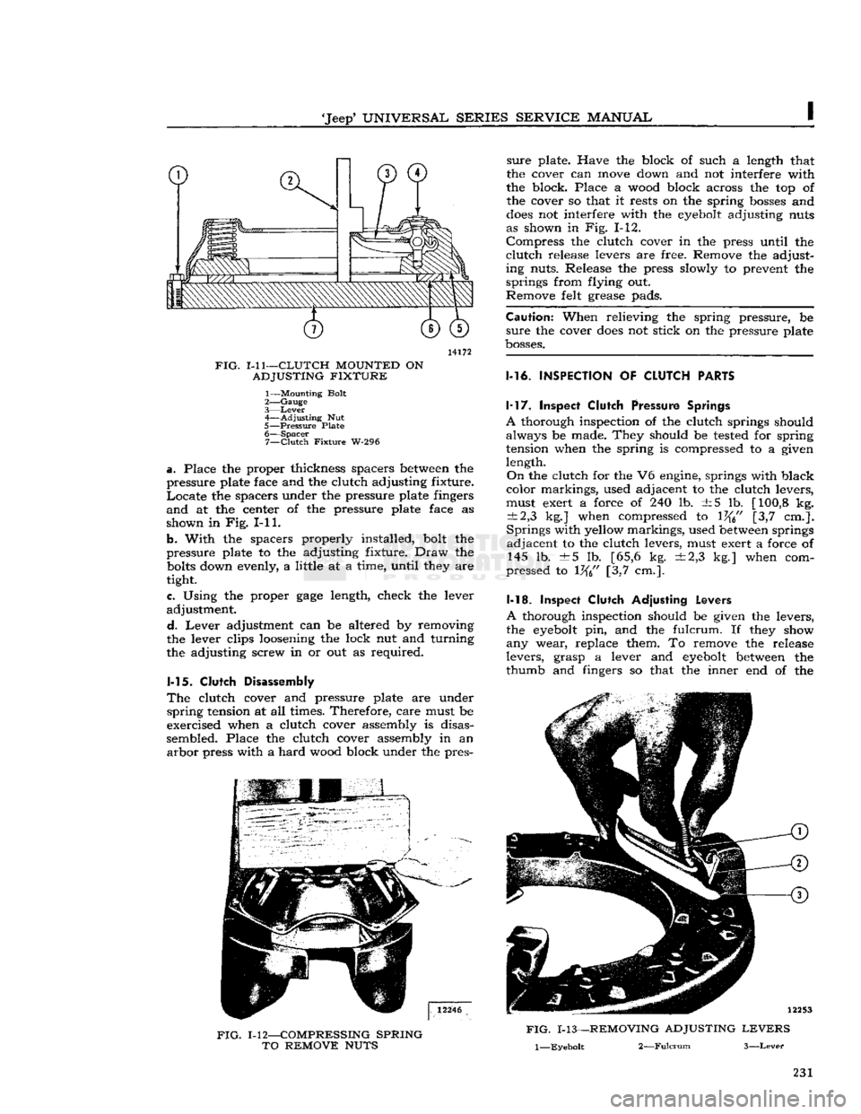
FIG.
1-11—CLUTCH
MOUNTED
ON
ADJUSTING
FIXTURE
1— Mounting Bolt
2—
Gauge
3—
Lever
4—
Adjusting
Nut
5—
Pressure
Plate 6—
Spacer
7—
Clutch
Fixture
W-296
a.
Place the proper thickness
spacers
between the
pressure
plate face and the
clutch
adjusting
fixture.
Locate the
spacers
under the
pressure
plate fingers
and at the center of the
pressure
plate face as
shown
in Fig. I-11.
b.
With
the
spacers
properly installed,
bolt
the
pressure
plate to the adjusting
fixture.
Draw the
bolts
down evenly, a
little
at a
time,
until
they are
tight.
e. Using the proper
gage
length, check the lever
adjustment.
d.
Lever adjustment can be altered by removing
the lever clips loosening the
lock
nut and
turning
the adjusting screw in or out as required.
1-15.
Clutch
Disassembly
The
clutch
cover and
pressure
plate are under
spring
tension at all times. Therefore,
care
must be
exercised when a
clutch
cover assembly is disas
sembled. Place the
clutch
cover assembly in an arbor
press
with
a hard
wood
block under the pres-
FIG.
1-12—COMPRESSING
SPRING
TO
REMOVE
NUTS
sure
plate. Have the block of such a length that
the cover can move down and not interfere
with
the block. Place a
wood
block
across
the top of the cover so that it
rests
on the spring
bosses
and
does
not interfere
with
the eyebolt adjusting nuts
as shown in Fig. 1-12.
Compress the
clutch
cover in the
press
until
the
clutch
release
levers are free. Remove the adjust
ing
nuts.
Release
the
press
slowly
to prevent the
springs
from
flying
out.
Remove
felt
grease
pads.
Caution:
When
relieving
the spring
pressure,
be
sure
the cover
does
not stick on the
pressure
plate
bosses.
1-16.
INSPECTION
OF
CLUTCH
PARTS 1-17. Inspect
Clutch
Pressure
Springs
A
thorough inspection of the
clutch
springs should always be made. They should be tested for spring
tension when the spring is compressed to a given
length.
On
the
clutch
for the V6 engine, springs
with
black
color
markings, used adjacent to the
clutch
levers,
must exert a force of 240 lb. ±5 lb. [100,8 kg.
±2,3
kg.] when compressed to 1%" [3,7 cm.].
Springs
with
yellow
markings, used between springs adjacent to the
clutch
levers, must exert a force of 145 lb. ±5 lb. [65,6 kg. ±2,3 kg.] when com
pressed
to 1%" [3,7 cm.].
1-18. Inspect
Clutch
Adjusting
Levers
A
thorough inspection should be given the levers,
the eyebolt pin, and the
fulcrum.
If they show
any wear, replace them. To remove the
release
levers,
grasp
a lever and eyebolt between the
thumb
and fingers so that the inner end of the
FIG.
1-13—REMOVING
ADJUSTING
LEVERS
l—Eyebolt
2—Fulcrum
3—Lever
231
Page 237 of 376
'Jeep'
UNIVERSAL
SERIES
SERVICE
MANUAL
I
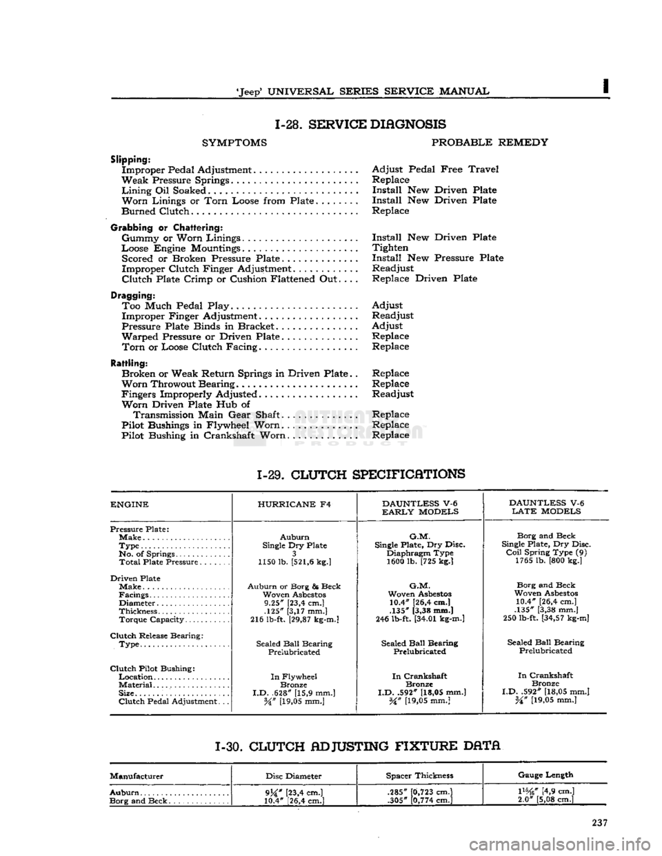
1-28.
SERVICE
DIAGNOSIS
SYMPTOMS
PROBABLE
REMEDY
Slipping:
Improper Pedal Adjustment Adjust Pedal Free
Travel
Weak Pressure Springs Replace
Lining
Oil Soaked Install New Driven Plate
Worn
Linings or
Torn
Loose from Plate Install New Driven Plate
Burned Clutch Replace
Grabbing
or
Chattering:
Gummy or Worn Linings Install New Driven Plate
Loose Engine
Mountings
Tighten Scored or Broken Pressure Plate Install New Pressure Plate
Improper Clutch Finger Adjustment............ Readjust
Clutch
Plate Crimp or Cushion Flattened Out.... Replace Driven Plate
Dragging: Too Much Pedal Play. Adjust Improper Finger Adjustment. Readjust
Pressure Plate Binds in Bracket Adjust
Warped Pressure or Driven Plate Replace
Torn
or Loose Clutch Facing. Replace
Rattling:
Broken or Weak Return Springs in Driven Plate.. Replace
Worn
Throwout Bearing Replace
Fingers Improperly Adjusted Readjust
Worn
Driven Plate Hub of Transmission Main Gear Shaft.............. Replace
Pilot Bushings in Flywheel Worn.
.............
Replace
Pilot Bushing in Crankshaft Worn Replace
1-29.
CLUTCH
SPECIFICATIONS
ENGINE
HURRICANE
F4
DAUNTLESS
V-6
DAUNTLESS
V-6
EARLY
MODELS
LATE
MODELS
Pressure Plate;
Auburn
G.M.
Borg and Beck
Type
Single
Dry Plate
Single
Plate, Dry Disc.
Single
Plate, Dry Disc.
No. of Springs 3 Diaphragm Type
Coil
Spring Type (9)
Total
Plate Pressure 1150 lb.
[521,6
kg.]
1600 lb. [725 kg.] 1765 lb. [800 kg.]
Driven Plate Make
Auburn
or Borg & Beck
G.M.
Borg and Beck
Facings Woven
Asbestos
Woven
Asbestos
Woven
Asbestos
Diameter 9.25" [23,4 cm.] 10.4" [26,4 cm.]
10.4" [26,4 cm.]
Thickness .125" [3,17 mm.] .135" [3,38 mm.]
.135" [3,38 mm.]
Torque Capacity 216 lb-ft.
[29,87
kg-m.]
246 lb-ft.
[34.01
kg-m.]
250 lb-ft.
[34,57
kg-m]
Clutch
Release Bearing: Sealed
Ball
Bearing
.
Type Sealed
Ball
Bearing Sealed
Ball
Bearing Sealed
Ball
Bearing
.
Type
Prelubricated Prelubricated
Prelubricated
Clutch
Pilot Bushing:
In
Crankshaft
In
Flywheel
In
Crankshaft
In
Crankshaft
Material
Bronze Bronze
Bronze
Size.
I.D.
.628" [15,9 mm.]
I.D.
.592"
[18,05
mm.]
I.D.
.592"
[18,05
mm.]
Clutch
Pedal Adjustment. .. W
[19,05
mm.]
%n
[19,05
mm.]
%n
[19,05
mm.]
1-30.
CLUTCH
ADJUSTING
FIXTURE
DATA
Manufacturer Disc Diameter Spacer Thickness Gauge Length
Auburn
9j£"
[23,4 cm.]
10.4" [26,4 cm.] .285"
.305"
0,723
cm.]
0,774
cm.]
mtf
[4,9 cm.]
2.0" [5,08 cm.]
9j£"
[23,4 cm.]
10.4" [26,4 cm.] .285"
.305"
0,723
cm.]
0,774
cm.]
mtf
[4,9 cm.]
2.0" [5,08 cm.]